# Introduction

Check out the content for FAQs, documentation, guides, etc..

​FAQs, documentation, guides, and help topics for developers, distributors, end users, etc..

## <img src="https://2999784448-files.gitbook.io/~/files/v0/b/gitbook-legacy-files/o/assets%2F-MBlD-pGvqUEQDs9SdgH%2F-MCGDz9h9JYa2e2N4-tw%2F-MCGEaU_1rqPQ-X31S1N%2Fknowledge%20(2).png?alt=media&amp;token=70dfc8c2-b384-442d-b54e-3c5ed03a57ed" alt="" data-size="line">General Knowledge <a href="#what-is-a-public-space" id="what-is-a-public-space"></a>

* [About IoT](https://docs.ifreeq.com/general-knowledge/about-iot)
* [Electricity](https://docs.ifreeq.com/general-knowledge/electricity)
* [Certification](https://docs.ifreeq.com/general-knowledge/certifications)
* [Industry Term](https://docs.ifreeq.com/general-knowledge/industry-terms)
* [Network Term](https://docs.ifreeq.com/general-knowledge/network-terms)
* [The Third-party Control](https://docs.ifreeq.com/general-knowledge/the-third-party-control)

## ​<img src="https://2999784448-files.gitbook.io/~/files/v0/b/gitbook-legacy-files/o/assets%2F-MBlD-pGvqUEQDs9SdgH%2F-MCGDz9h9JYa2e2N4-tw%2F-MCGEWWhGHJudQ69hid6%2Fdevelop(5).png?alt=media&amp;token=d4d160e2-16e3-43a9-822c-42104ece7513" alt="" data-size="line"> Developer documentation <a href="#what-is-a-private-space" id="what-is-a-private-space"></a>

* [Introduction  ](https://docs.ifreeq.com/developer/introduction)
* [Quick Start  ](https://docs.ifreeq.com/developer/quick-start)
* [Configure in Platform  ](https://docs.ifreeq.com/developer/configure-in-platform)
* [Device Development  ](https://docs.ifreeq.com/developer/device-development)
* [Smart Product Solution](https://docs.ifreeq.com/developer/smart-product-solution)

## ​<img src="https://2999784448-files.gitbook.io/~/files/v0/b/gitbook-legacy-files/o/assets%2F-MBlD-pGvqUEQDs9SdgH%2F-MCGNnArba17DgbZWoGK%2F-MCGOB5VrI2zW3byA7Fi%2FFAQs.png?alt=media&amp;token=89e2a8eb-c761-435f-bc4d-b2d54982af42" alt="" data-size="line"> FAQs <a href="#setting-up-visibility" id="setting-up-visibility"></a>

* [Device Development  ](https://docs.ifreeq.com/faqs/device-development)
* [Smart Product Solution](https://docs.ifreeq.com/faqs/smart-product-solution)
* [Products](https://docs.ifreeq.com/faqs/products)
* [More FAQs](https://docs.ifreeq.com/faqs/more-faqs)

## &#x20;<img src="https://2999784448-files.gitbook.io/~/files/v0/b/gitbook-legacy-files/o/assets%2F-MBlD-pGvqUEQDs9SdgH%2F-MCGNnArba17DgbZWoGK%2F-MCGOG31bgSFvjFJ8iJA%2Fweb-link.png?alt=media&amp;token=dc1522f2-e62d-4e5c-8a6b-9d7761db5fc2" alt="" data-size="line"> Links to: <a href="#unlisted" id="unlisted"></a>

* [www.ifreeq.com](https://www.ifreeq.com)
* [store.ifreeq.com](https://store.ifreeq.com/)
* [www.ifreeq.com.cn](https://www.ifreeq.com.cn/)
* [expo.ifreeq.com](https://expo.ifreeq.com/)


# Update Log

Be sure to not miss out anything about our update

## 2020/08/21

* Add Home Automation Brand
* Add Home Automation Catalog

## 2020/07/15

Fixed some issues, modified the '[Introduction](https://docs.ifreeq.com/)' page, and added the "[Update Log](https://docs.ifreeq.com/update-log)" page.

## 2020/07/12

We update the FAQs documents, including FAQs about:

* Device Development
* Smart Product Solution
* Products

## 2020/07/10

We update the developer center's documents, including:

* Configure in Platform
* Device Development
* Smart Product Solution
* Quick Start

## 2020/07/07

We build our documentation center. And update the general knowledge parts.


# About IoT

## Introduction

### Definition

Internet of Things (IoT) uses sensors, chips, and wireless modules to interconnect all things for information exchange and communications. It is an extension of the Internet that uses computers and mobile terminals to interconnect people.

### Elements

* Devices with network connection capabilities
* Cloud services (data monitoring, storage, and analysis services and data security services)
* Control terminals: apps, cloud, and smart speakers such as Google Home and Amazon Echo

### Phases

* Sensing and control
* Scene association
* Robot/artificial intelligence (AI)

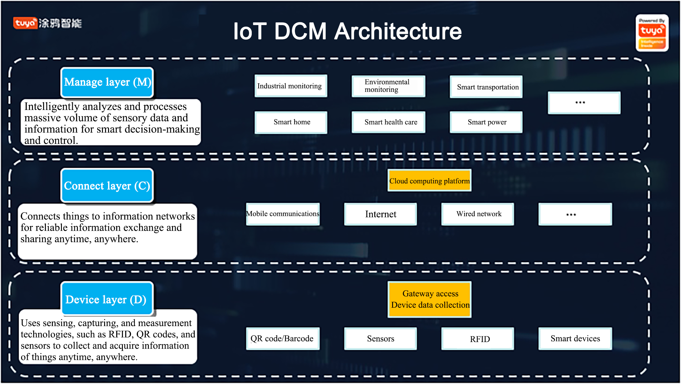
### DCM Architecture

![Introduction of IoT](https://airtake-public-data.oss-cn-hangzhou.aliyuncs.com/goat/20200227/d2db34febc104b2490d57eb2be0fc0df.png)

## Industry Overview

### Rapid Increase in Device Connections

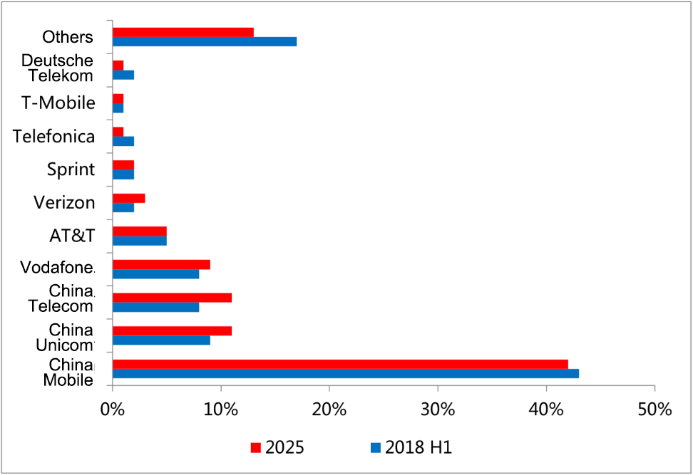
In 2018, the number of IoT connections in China increased rapidly. A report from Counterpoint, a well-known market research company, showed that the number of IoT connections of three major Chinese telecom operators took up more than 60% of global cellular IoT connections in 2018, and this share is expected to be retained by 2025.

![Introduction of IoT](https://airtake-public-data.oss-cn-hangzhou.aliyuncs.com/goat/20200227/f89822c96bfd4d438abdd2e13820b9b4.png)

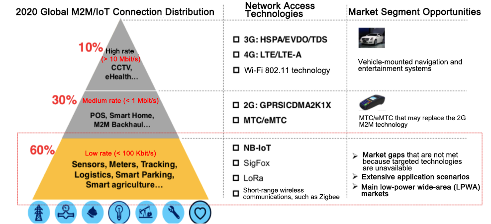
IDC estimated that IoT will create a value of US$1.46 trillion by 2020 and generate a large number of opportunities in various market segments.

![Introduction of IoT](https://airtake-public-data.oss-cn-hangzhou.aliyuncs.com/goat/20200227/d9de73e4eaa543ae8a67872f7297ddb9.png)

![Introduction of IoT](https://airtake-public-data.oss-cn-hangzhou.aliyuncs.com/goat/20200227/83c0006e093d4f25bc7361c3708d059f.png)

### Promising and Challenging 5G Era

5G has become the hottest topic in the technical world. In 2019, Ministry of Industry and Information Technology (MIIT) issued temporary 5G licenses. This started the 5G era.

Before commercial application, 5G is in a wild speculation period just like other new technologies. Typical operators, however, are still very careful about making 5G infrastructure investments.

According to 3GPP's work progress, established 5G standards focused on Enhanced Mobile Broadband (eMBB). This is also the focus of commercial applications in 2019 and 2020. However, eMBB mainly applies to the mobile Internet and has limited supports for IoT applications. Ultra-Reliable Low-Latency Communication (URLLC) and Massive Machine Type Communication (mMTC) are core technologies for applying 5G to IoT. However, these two technologies are not standardized yet and require time for commercial application. Therefore, it takes time for boosting the IoT development with 5G.

### Cloud, Edge, and Device Collaboration, and Further AI+IoT Integration

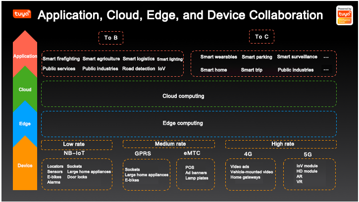
The edge layer is added to the original four-layer architecture because edge computing has become more and more important in IoT businesses. Edge computing, cloud computing, and device computing form a collaborative system that offers reliable, cost-effective IoT application solutions based on user scenes, resource constraints, and business timeliness. Cloud computing vendors, IT vendors, operators, and virtual industry vendors have reached a consensus on using IoT solutions for cloud, edge, and device collaboration even though they have different opinions about edge computing, edge node positions, and edge computing capabilities.

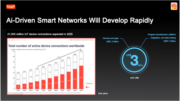
We believed that the combination of AI and IoT would make a big difference according to the Overall Industrial Report of the Chinese IoT Industry in 2017 and 2018. In 2019, AI giants were exploring how to use AI to empower industries of various national economic sectors, and the integration with IoT is crucially important. AI has integrated with multiple IoT layers, including the device, edge, and cloud layers.

Many technical companies, such as Hikvision, Megvii, and Horizon Robotics have released IoT-related platforms and products. The combination of AI and IoT will implement more products and services and bring more IoT technical solutions into reality.

![Introduction of IoT](https://airtake-public-data.oss-cn-hangzhou.aliyuncs.com/goat/20200227/8b5a94a317754bbea2a94ef53f423e79.png)


# Electricity

* [History of domestic electricity](https://docs.ifreeq.com/general-knowledge/electricity/history-of-domestic-electricity)
* [Plug & socket types](https://docs.ifreeq.com/general-knowledge/electricity/plug-and-socket-types-around-the-world)
* [Plug, socket & voltage by country](https://docs.ifreeq.com/general-knowledge/electricity/plug-socket-and-voltage-by-country)
* [World map showing the spread of plug types](https://docs.ifreeq.com/general-knowledge/electricity/world-map-showing-the-spread-of-plug-types)
* [Useful information for travellers](https://docs.ifreeq.com/general-knowledge/electricity/useful-information-for-travellers)
* [Three-phase electric power (industrial applications only)](https://docs.ifreeq.com/general-knowledge/electricity/three-phase-electric-power-industrial-applications-only)


# Plug & socket types around the world

There are currently 15 types of electrical outlet plugs in use today, each of which has been assigned a letter by the US Department of Commerce International Trade Administration (ITA), starting with A and moving through the alphabet. These letters are completely arbitrary: they don’t actually mandate anything.

Click [here](https://docs.ifreeq.com/general-knowledge/electricity/world-map-showing-the-spread-of-plug-types) for a global map showing the spread of the different plug types used around the world.

Click [here](https://docs.ifreeq.com/general-knowledge/electricity/plug-socket-and-voltage-by-country) for a detailed list of the countries of the world with their respective plug and outlet types, voltage and frequency.

## Type A

![](https://www.worldstandards.eu/wp-content/uploads/electricity-tiles-type-A-200-px.jpg)

* mainly used in the USA, Canada, Mexico & Japan (for a full list, click [here](https://docs.ifreeq.com/general-knowledge/electricity/plug-socket-and-voltage-by-country))
* 2 pins
* not grounded
* 15 A
* almost always 100 – 127 V
* socket compatible with plug type A

[Learn more](https://docs.ifreeq.com/general-knowledge/electricity/plug-and-socket-types-around-the-world/power-plug-and-outlet-types-a-and-b)

## Type B

![](https://www.worldstandards.eu/wp-content/uploads/electricity-tiles-type-B-200-px.jpg)

* mainly used in the USA, Canada, Mexico & Japan (for a full list, click [here](https://docs.ifreeq.com/general-knowledge/electricity/plug-socket-and-voltage-by-country))
* 3 pins
* grounded
* 15 A
* almost always 100 – 127 V
* socket compatible with plug types A & B

[Learn more](https://docs.ifreeq.com/general-knowledge/electricity/plug-and-socket-types-around-the-world/power-plug-and-outlet-types-a-and-b)

## Type C

![](https://www.worldstandards.eu/wp-content/uploads/electricity-tiles-type-C-200-px.jpg)

* commonly used in Europe, South America & Asia (for a full list, click [here](https://docs.ifreeq.com/general-knowledge/electricity/plug-socket-and-voltage-by-country))
* 2 pins
* not grounded
* 2.5 A, 10 A & 16 A
* almost always 220 – 240 V
* socket compatible with plug type C

[Learn more](https://docs.ifreeq.com/general-knowledge/electricity/plug-and-socket-types-around-the-world/power-plug-and-outlet-type-c)

## Type D

![](https://www.worldstandards.eu/wp-content/uploads/electricity-tiles-type-D-200-px.jpg)

* mainly used in India (for a full list, click [here](https://docs.ifreeq.com/general-knowledge/electricity/plug-socket-and-voltage-by-country))
* 3 pins
* grounded
* 5 A
* 220 – 240 V
* socket compatible with plug type D (partial and unsafe compatibility with C, E & F)

[Learn more](https://docs.ifreeq.com/general-knowledge/electricity/plug-and-socket-types-around-the-world/power-plug-and-outlet-type-d)

## Type E

![](https://www.worldstandards.eu/wp-content/uploads/electricity-tiles-type-E-200-px.jpg)

* primarily used in France, Belgium, Poland, Slovakia & Czechia (for a full list, click [here](https://docs.ifreeq.com/general-knowledge/electricity/plug-socket-and-voltage-by-country))
* 2 pins
* grounded
* 16 A
* 220 – 240 V
* socket compatible with plug types C, E & F

[Learn more](https://docs.ifreeq.com/general-knowledge/electricity/plug-and-socket-types-around-the-world/power-plug-and-outlet-type-e)

## Type F

![](https://www.worldstandards.eu/wp-content/uploads/electricity-tiles-type-F-200-px.jpg)

* used almost everywhere in Europe & Russia, except for the UK & Ireland (for a full list, click [here](https://docs.ifreeq.com/general-knowledge/electricity/plug-socket-and-voltage-by-country))
* 2 pins
* grounded
* 16 A
* 220 – 240 V
* socket compatible with plug types C, E & F

[Learn more](https://docs.ifreeq.com/general-knowledge/electricity/plug-and-socket-types-around-the-world/power-plug-and-outlet-type-f)

## Type G

![](https://www.worldstandards.eu/wp-content/uploads/electricity-tiles-type-G-200-px.jpg)

* mainly used in the United Kingdom, Ireland, Malta, Malaysia & Singapore (for a full list, click [here](https://docs.ifreeq.com/general-knowledge/electricity/plug-socket-and-voltage-by-country))
* 3 pins
* grounded
* 13 A
* 220 – 240 V
* socket compatible with plug type G

[Learn more](https://docs.ifreeq.com/general-knowledge/electricity/plug-and-socket-types-around-the-world/power-plug-and-outlet-type-g)

## Type H

![](https://www.worldstandards.eu/wp-content/uploads/electricity-tiles-type-H-200-px.jpg)

* used exclusively in Israel, the West Bank & the Gaza Strip (for a full list, click [here](https://docs.ifreeq.com/general-knowledge/electricity/plug-socket-and-voltage-by-country))
* 3 pins
* grounded
* 16 A
* 220 – 240 V
* socket compatible with plug types C & H (partial and unsafe compatibility with E & F)

[Learn more](https://docs.ifreeq.com/general-knowledge/electricity/plug-and-socket-types-around-the-world/power-plug-and-outlet-type-h)

## Type I

![](https://www.worldstandards.eu/wp-content/uploads/electricity-tiles-type-I-200-px.jpg)

* mainly used in Australia, New Zealand, China & Argentina (for a full list, click [here](https://docs.ifreeq.com/general-knowledge/electricity/plug-socket-and-voltage-by-country))
* 2 or 3 pins
* 2 pins: not grounded / 3 pins: grounded
* 10 A
* 220 – 240 V
* socket compatible with plug type I

[Learn more](https://docs.ifreeq.com/general-knowledge/electricity/plug-and-socket-types-around-the-world/power-plug-and-outlet-type-i)

## Type J

![](https://www.worldstandards.eu/wp-content/uploads/electricity-tiles-type-J-200-px.jpg)

* used almost exclusively in Switzerland & Liechtenstein (for a full list, click [here](https://docs.ifreeq.com/general-knowledge/electricity/plug-socket-and-voltage-by-country))
* 3 pins
* grounded
* 10 A
* 220 – 240 V
* socket compatible with plug types C & J

[Learn more](https://docs.ifreeq.com/general-knowledge/electricity/plug-and-socket-types-around-the-world/power-plug-and-outlet-type-j)

## Type K

![](https://www.worldstandards.eu/wp-content/uploads/electricity-tiles-type-K-200px.jpg)

* used almost exclusively in Denmark & Greenland (for a full list, click [here](https://docs.ifreeq.com/general-knowledge/electricity/plug-socket-and-voltage-by-country))
* 3 pins
* grounded
* 16 A
* 220 – 240 V
* socket compatible with plug types C & K (partial and unsafe compatibility with E & F)

[Learn more](https://docs.ifreeq.com/general-knowledge/electricity/plug-and-socket-types-around-the-world/power-plug-and-outlet-type-k)

## Type L

![](https://www.worldstandards.eu/wp-content/uploads/electricity-tiles-type-L-200-px.jpg)

* used almost exclusively in Italy & Chile (for a full list, click [here](https://docs.ifreeq.com/general-knowledge/electricity/plug-socket-and-voltage-by-country))
* 3 pins
* grounded
* 10 A & 16 A
* 220 – 240 V
* 10 A socket compatible with plug types C & L (10 A version)
* 16 A socket compatible with plug type L (16 A version)

[Learn more](https://docs.ifreeq.com/general-knowledge/electricity/plug-and-socket-types-around-the-world/power-plug-and-outlet-type-l)

## Type M

![](https://www.worldstandards.eu/wp-content/uploads/electricity-tiles-type-M-200-px.jpg)

* mainly used in South Africa (for a full list, click [here](https://docs.ifreeq.com/general-knowledge/electricity/plug-socket-and-voltage-by-country))
* 3 pins
* grounded
* 15 A
* 220 – 240 V
* socket compatible with plug type M

[Learn more](https://docs.ifreeq.com/general-knowledge/electricity/plug-and-socket-types-around-the-world/power-plug-and-outlet-type-m)

## Type N

![](https://www.worldstandards.eu/wp-content/uploads/electricity-tiles-type-N-200-px.jpg)

* used in Brazil and South Africa (for a full list, click [here](https://docs.ifreeq.com/general-knowledge/electricity/plug-socket-and-voltage-by-country))
* 3 pins
* grounded
* 10 A, 16 A & 20 A
* 100 – 240 V
* socket compatible with plug types C & N

[Learn more](https://docs.ifreeq.com/general-knowledge/electricity/plug-and-socket-types-around-the-world/power-plug-and-outlet-type-n)

## Type O

![](https://www.worldstandards.eu/wp-content/uploads/electricity-tiles-type-O-200-px.jpg)

* used exclusively in Thailand
* 3 pins
* grounded
* 16 A
* 220 – 240 V
* socket compatible with plug types C & O (partial and unsafe compatibility with E & F)

[Learn more](https://docs.ifreeq.com/general-knowledge/electricity/plug-and-socket-types-around-the-world/power-plug-and-outlet-type-o)\ <br>


# Power plug & outlet Types A & B

There are two types of domestic wall outlets in use in the US, Canada, Japan and Central America: the ungrounded type A (NEMA 1-15) and the grounded type B (NEMA 5-15). (The full list of countries that use types A & B can be found [here](https://docs.ifreeq.com/general-knowledge/electricity/plug-socket-and-voltage-by-country).)

## TYPE A

![](https://2999784448-files.gitbook.io/~/files/v0/b/gitbook-legacy-files/o/assets%2F-MBlD-pGvqUEQDs9SdgH%2F-MBpfmGZwp3gp8E8cZAQ%2F-MBpj1wrR5I9hV6OqSLk%2Fimage.png?alt=media\&token=b2c5b541-0187-4c41-b9bc-f77f60a2d83a)

This class II ungrounded plug with two flat parallel prongs is pretty much standard in most of North and Central America. It is known as NEMA 1-15 and was invented in 1904 by Harvey Hubbell II. The plug has two flat 1.5 mm thick blades, measuring 15.9 – 18.3 mm in length and spaced 12.7 mm apart. Type A plugs are generally polarised and can only be inserted one way because the two blades do not have the same width. The blade connected to neutral is 7.9 mm wide and the hot blade is 6.3 mm wide. This plug is rated at 15 A. Since 1965, ungrounded type A outlets are not permitted anymore in new constructions in the United States and Canada, but they can still be found in older buildings.

![](https://2999784448-files.gitbook.io/~/files/v0/b/gitbook-legacy-files/o/assets%2F-MBlD-pGvqUEQDs9SdgH%2F-MBpfmGZwp3gp8E8cZAQ%2F-MBpj4Pnj-yXP5TS0-Nk%2Fimage.png?alt=media\&token=2b98492b-0882-4109-96e9-95508dfc0106)

Type A and B plugs have two flat prongs with (often, but not always) a hole near the tip. These holes aren’t there without a reason. If you were to take apart a type A or B socket and look at the contact wipers that the prongs slide into, you would find that in some cases they have have bumps on them. These bumps fit into the holes so that the outlet can grip the plug’s prongs more firmly. This prevents the plug from slipping out of the socket due to the weight of the plug and cord. It also improves the contact between the plug and the outlet. Some sockets, however, do not have those bumps but just two spring-action blades that grip the sides of the plug pin, in which case the holes are not necessary.

![](https://2999784448-files.gitbook.io/~/files/v0/b/gitbook-legacy-files/o/assets%2F-MBlD-pGvqUEQDs9SdgH%2F-MBpfmGZwp3gp8E8cZAQ%2F-MBpj6xjigxxRXTnwi65%2Fimage.png?alt=media\&token=7065dfe5-ca45-4422-aa1c-6210381d3a1e)

There are also some special outlets which allow you to lock the cord into the socket, by putting rods through the holes. In this way, vending machines and the like cannot be unplugged. Moreover, electrical devices can be *factory-sealed* by the manufacturer using a plastic tie or a small padlock through one or both of the plug prong holes. For example, a manufacturer might apply a plastic band through the hole and attach it to a tag that says: “You must do X or Y before plugging in this device”. The user cannot plug in the device without removing the tag, so the user is sure to see the tag.

## **TYPE B**

![electricity - type B (plug)](https://www.worldstandards.eu/wp-content/uploads/electricity-type-B-plug-300x131.jpg)

This class I plug is designated as American standard NEMA 5-15. It has two flat 1.5 mm thick blades, spaced 12.7 mm apart, measuring 15.9 – 18.3 mm in length and 6.3 mm in width. It also has a 4.8 mm diameter round or U-shaped earth pin, which is 3.2 mm longer than the two flat blades, so the device is grounded before the power is connected. The centre-to-centre distance between the grounding pin and the middle of the imaginary line connecting the two power blades is 11.9 mm. The plug is rated at 15 amps.

![electricity - type B (socket)](https://www.worldstandards.eu/wp-content/uploads/electricity-type-B-socket-218x300.jpg)

In some parts of Central and South America, grounded type B outlets are still rather uncommon. Therefore people often simply cut off the earth pin of a type B plug in order to mate it with a two-pole ungrounded socket.

![](https://www.worldstandards.eu/wp-content/uploads/electricity-type-B-socket-plug-pulled-halfway-out-300x225.jpg)

Type A and B plugs are not insulated (i.e. the pin shanks do not have a black covering towards the plug body like [type C](https://docs.ifreeq.com/general-knowledge/electricity/plug-and-socket-types-around-the-world/power-plug-and-outlet-type-c), [G](https://docs.ifreeq.com/general-knowledge/electricity/plug-and-socket-types-around-the-world/power-plug-and-outlet-type-g), [I](https://docs.ifreeq.com/general-knowledge/electricity/plug-and-socket-types-around-the-world/power-plug-and-outlet-type-i), [L](https://docs.ifreeq.com/general-knowledge/electricity/plug-and-socket-types-around-the-world/power-plug-and-outlet-type-l) or [N plugs](https://docs.ifreeq.com/general-knowledge/electricity/plug-and-socket-types-around-the-world/power-plug-and-outlet-type-n)) and the outlets are not recessed into the wall, which means that if a the plug is pulled halfway out, its prongs are still connected to the socket. Type A and B sockets are potentially dangerous, since the distance between the receptacle and a partially pulled-out plug is big enough to touch the pins with your fingers or with a metal object such as a teaspoon.<br>


# Power plug & outlet Type C

![ The ‘normal’, most common type C plug, rated at 2.5 amperes, is only used for low energy-consuming appliances.](https://2999784448-files.gitbook.io/~/files/v0/b/gitbook-legacy-files/o/assets%2F-MBlD-pGvqUEQDs9SdgH%2F-MBpj9qHXj7PZeFZc58m%2F-MBpj_uvosX9YoUzcE0X%2Fimage.png?alt=media\&token=5cb5ec2a-dce1-497c-8c95-54786b2f1624)

Type C is used in all countries of Europe except the United Kingdom, Ireland, Cyprus and Malta. (Click [here](https://docs.ifreeq.com/general-knowledge/electricity/plug-socket-and-voltage-by-country) for the full list of all countries that use type C)

Type C is probably the single most widely used international plug. This two-wire plug is ungrounded, unpolarised and has two round prongs. It is popularly known as the Europlug which is described in CEE 7/16. The plug has two 4 mm round pins, measuring 19 mm in length on centres spaced 18.6 mm apart at the base and 17.5 mm apart at the tip. The two pins have 10 mm long insulated sleeves. They converge slightly, but they are relatively flexible which allows the plug to mate with any socket that accepts 4.0 – 4.8 mm round contacts on 17.5 – 19 mm centres. The plug is generally limited for use in class II applications that require 2.5 amps or less.

![](https://2999784448-files.gitbook.io/~/files/v0/b/gitbook-legacy-files/o/assets%2F-MBlD-pGvqUEQDs9SdgH%2F-MBpj9qHXj7PZeFZc58m%2F-MBpju_AR3ymV0Ot_QcS%2Fimage.png?alt=media\&token=7fab1efb-b5a8-47f7-81ef-7218ebe6174d)

There is also a second, less frequently used version of the type C plug (CEE 7/17), which is rated at either 10 A or 16 A. Its pins have the same length (19 mm) as the 2.5 amp version, but they are not insulated and have a slightly larger diameter (4.8 mm instead of 4 mm). Appliances that do not require earthing, but which are high energy-consuming, are almost always fitted with this kind of plug (e.g. hair dryers, bathroom heaters, vacuum cleaners, etc.). Please note that [type N](https://docs.ifreeq.com/general-knowledge/electricity/plug-and-socket-types-around-the-world/power-plug-and-outlet-type-n) sockets, which are used in Brazil and South Africa, are incompatible with the 16 amp version of type C because of the shape of the plug. [Type N sockets](https://docs.ifreeq.com/general-knowledge/electricity/plug-and-socket-types-around-the-world/power-plug-and-outlet-type-n) are recessed and hexagonally-shaped, and only accept hexagonally-shaped plugs.

![The 16 ampere version of the type C plug, used for high energy-consuming appliances.](https://2999784448-files.gitbook.io/~/files/v0/b/gitbook-legacy-files/o/assets%2F-MBlD-pGvqUEQDs9SdgH%2F-MBpj9qHXj7PZeFZc58m%2F-MBpk7TIfma-bNwpUh-W%2Fimage.png?alt=media\&token=e0f5f556-6e42-44f1-afae-5ab73b635d15)

Type C plugs are commonly used in all countries of Europe except in the United Kingdom, Ireland, Cyprus and Malta. They are also used in various parts of the developing world. Although type C plugs are used in so many places around the world, the opposite is true for type C sockets. This kind of socket is the older and ungrounded variant of the type E, F, J, K, L, N and O socket. Nowadays most countries demand grounded sockets to be installed in new buildings. Since type C sockets are unearthed, they have become illegal almost everywhere and they are being replaced by type E, F, H, J, K, L, N or O (depending on the country). So as to leave no doubt: only the sockets have become illegal, the plugs remain in use of course. The ‘normal’, 2.5 amp type C plug fits perfectly into a type E, F, H, J, K, L, N or O socket.


# Power plug & outlet Type D

Whereas type C plugs and type D sockets could be considered an unsafe, but ‘relatively workable’ combination, using E/F plugs with D outlets is downright dangerous. The centres of the pins of type E & F plugs are slightly closer together (19 mm vs 19.1 mm) than those of type D, but unlike Europlugs (type C), they do not have flexible prongs. This means they literally have to be forced into the receptacle. Obviously, this kind of improper use poses an enormous safety hazard for a number of reasons. Firstly – unlike type C – E & F plugs are supposed to be grounded, but when they are used with type D outlets, this won’t be the case. So, be prepared for a sparking receptacle and a regularly tripping circuit breaker. Moreover, type E and F plugs cannot be fully inserted into a D socket, because the pins are longer than the pins of type D plugs (19 mm vs 14.9 mm). This means that 4.1 mm of the pins of plug types E & F will still be exposed when plugged in and if you were to touch the live prong, you most certainly will get an electric shock. This risk does not exist with type C plugs, since their pins are coated in insulation.

![](https://2999784448-files.gitbook.io/~/files/v0/b/gitbook-legacy-files/o/assets%2F-MBlD-pGvqUEQDs9SdgH%2F-MBpkDgquVJ5NJlZ_z_c%2F-MBpmZHfjzrtq-7TTXvT%2Fimage.png?alt=media\&token=72fa6453-7260-43f2-b24a-61b84cbd3ea6)

Although type D is now almost exclusively used in India and Nepal, it can still occasionally be found in hotels in the UK. It should be noted that tourists should not attempt to connect anything to a BS 546 round-pin outlet found in the UK as it is likely to be on a circuit that has a special purpose: e.g. for providing direct current (DC) or for plugging in lamps that are controlled by a light switch or a dimmer.

![](https://2999784448-files.gitbook.io/~/files/v0/b/gitbook-legacy-files/o/assets%2F-MBlD-pGvqUEQDs9SdgH%2F-MBpkDgquVJ5NJlZ_z_c%2F-MBpmbmDy73FzjSXdUT_%2Fimage.png?alt=media\&token=e5b7b2ad-1b84-4cb9-99b2-f08e7b4eb4fc)

Type D plugs are among the most dangerous ones in the world: the prongs are not insulated (i.e. the pin shanks do not have a black covering towards the plug body like type C, G, I, L or N plugs), which means that if a type D plug is pulled halfway out, its prongs are still connected to the socket! Little children run the risk of electrocuting themselves when pulling such a plug out and putting their fingers around it. Type D outlets are not recessed into the wall, so they do not provide any protection from touching the live pins either.


# Power plug & outlet Type E

Type E is primarily used in France, Belgium, Poland, Slovakia, the Czech Republic, Tunisia and Morocco. (Click [here](https://docs.ifreeq.com/general-knowledge/electricity/plug-socket-and-voltage-by-country) for the full list of all countries that use type E)

![](https://2999784448-files.gitbook.io/~/files/v0/b/gitbook-legacy-files/o/assets%2F-MBlD-pGvqUEQDs9SdgH%2F-MBpkDgquVJ5NJlZ_z_c%2F-MBpmxjalLLfgARe1mvQ%2Fimage.png?alt=media\&token=4b84dabf-18ed-45e7-967d-fe1276dc7ef9)

France, Belgium and some other countries have standardized on a socket which is different from the CEE 7/4 socket (type F) that is standard in Germany and other continental European countries. Fortunately, type F plugs are fully compatible with type E sockets and the other way round. In the past, however, this wasn’t the case. The reason for the initial incompatibility was that grounding in the E socket is accomplished with a round male pin, which is permanently mounted in the socket. Old type F plugs did not have a grounding hole to accept the earth pin of the type E socket. This grounding pin is 14 mm long and has a diameter of 4.8 mm.  The plug itself is similar to C except that it is round and has the addition of a female contact to accept the socket’s grounding pin. The plug has two 4.8 mm round pins, measuring 19 mm in length on centres spaced 19 mm apart. The centre-to-centre distance between the female contact and the middle of the imaginary line connecting the two power pins is 10 mm.

![](https://2999784448-files.gitbook.io/~/files/v0/b/gitbook-legacy-files/o/assets%2F-MBlD-pGvqUEQDs9SdgH%2F-MBpkDgquVJ5NJlZ_z_c%2F-MBpn-RYexuzsiUArqYU%2Fimage.png?alt=media\&token=716ddc1e-0fce-490e-a5da-82522320e347)

In order to bridge the differences between sockets E and F, the CEE 7/7 plug was developed (see photo on the left): it has grounding clips on both sides to mate with the type F socket and a female contact to accept the grounding pin of the type E socket. The original type E plug, which does not have grounding clips, is no longer used, although very rarely it can still be found on some older appliances. Note that the CEE 7/7 plug is polarised when used with a type E outlet. The plug is rated at 16 amps. Above that, equipment must either be wired permanently to the mains or connected via another higher power connector such as the IEC 60309 system. A type C plug fits perfectly into a type E socket. The socket is recessed by 15 mm, so partially inserted plugs do not present a shock hazard.


# Power plug & outlet Type F (Schuko)

\
&#x20;Type F is used, for instance, in Germany, Austria, the Netherlands, Sweden, Finland, Norway, Portugal, Spain and Eastern Europe. (Click [here](https://docs.ifreeq.com/general-knowledge/electricity/plug-socket-and-voltage-by-country) for the full list of all countries that use type F)

Plug F is known as CEE 7/4 and commonly called “Schuko plug”, which is the acronym of “**Schu**tz**ko**ntakt”, a German word meaning “protection contact” or “safety contact”. The plug was designed in Germany shortly after the First World War. It goes back to a patent (DE 370538) granted in 1926 to Albert Büttner, a Bavarian manufacturer of electrical accessories.

![](https://2999784448-files.gitbook.io/~/files/v0/b/gitbook-legacy-files/o/assets%2F-MBlD-pGvqUEQDs9SdgH%2F-MBpkDgquVJ5NJlZ_z_c%2F-MBpnDo3iSvuimwll61N%2Fimage.png?alt=media\&token=b1879bd9-ded9-4599-b0c5-6b7df285f084)

Type F is similar to C except that it is round and has the addition of two grounding clips on the side of the plug. The plug has two 4.8 mm round pins, measuring 19 mm in length on centres spaced 19 mm apart. The distance between either of the two earthing clips and the middle of the imaginary line connecting the centres of the two power pins is 16 mm.

![](https://2999784448-files.gitbook.io/~/files/v0/b/gitbook-legacy-files/o/assets%2F-MBlD-pGvqUEQDs9SdgH%2F-MBpkDgquVJ5NJlZ_z_c%2F-MBpnGmi31mcu5XTmCdf%2Fimage.png?alt=media\&token=b70f68ec-c712-4c79-90d7-02c3a248fb9e)

Because the CEE 7/4 plug can be inserted in either direction into the receptacle, the Schuko connection system is unpolarised (i.e. line and neutral are connected at random). It is used in applications up to 16 amps. Above that, equipment must either be wired permanently to the mains or connected via another higher power connector such as the IEC 60309 system.

Type F plugs are fully compatible with type E sockets. This was not the case in the past, but fortunately common sense prevailed. A hybrid E/F plug (officially called CEE 7/7) was developed in order to bridge the differences between E and F sockets. This plug, which is shown above, has earthing clips on both sides to mate with the type F socket and a female contact to accept the earth pin of the type E socket. The original type F plug, which does not have this female contact, is now obsolete, but a rewireable version may still be available at some DIY shops. A type C plug fits perfectly into a type F socket. The socket is recessed by 15 mm, so partially inserted plugs do not present a shock hazard.


# Power plug & outlet Type G

Type G is mainly used in the United Kingdom, Ireland, Cyprus, Malta, Malaysia, Singapore and Hong Kong. (Click [here](https://docs.ifreeq.com/general-knowledge/electricity/plug-socket-and-voltage-by-country) for the full list of all countries that use type G)

![](https://2999784448-files.gitbook.io/~/files/v0/b/gitbook-legacy-files/o/assets%2F-MBlD-pGvqUEQDs9SdgH%2F-MBpnM2HLrpLemJq_hFx%2F-MBpo6pG02msYQRToWiY%2Fimage.png?alt=media\&token=d8dea32e-62b9-404a-99f7-1575ee36e40a)

This 13 amp plug has three rectangular prongs that form an isosceles triangle. The central earth pin is 4 by 8 mm and 22.7 mm long. Line and neutral pins are 4 by 6.35 mm and 17.7 mm long, on centres spaced 22.2 mm apart. The centre-to-centre distance between the earth pin and the middle of the imaginary line connecting the two power pins is 22.2 mm. The 9-mm long insulated sleeves prevent accidental contact with a bare connector while the plug is partially inserted.

British Standard BS 1363 requires use of a three-wire grounded and fused plug for all connections to the power mains. Two-wire class II appliances are not earthed and often have a plastic grounding pin which only serves to open the shutters of the outlet. The lack of such an earth pin on a type C plug makes it impossible to connect it to a type G receptacle, although it can actually be forced into the socket by sticking a pointy object into the centre hole of the power outlet, which opens up the two other holes. Just to be perfectly clear, this is not a piece of advice; it’s simply an observation…

![](https://2999784448-files.gitbook.io/~/files/v0/b/gitbook-legacy-files/o/assets%2F-MBlD-pGvqUEQDs9SdgH%2F-MBpnM2HLrpLemJq_hFx%2F-MBpo2TopR7TaxjDt48F%2Fimage.png?alt=media\&token=5aa3dbf4-7355-4fa2-94fb-59bf6176cc9c)

In the UK, the power sockets in a house are connected by means of *ring circuits*, which are protected by 32 A circuit breakers. This type of wiring is rarely used outside the UK and requires the use of *fused* plugs. Small appliances, like mobile phone chargers, usually have a 3 A cartridge fuse inside the plug; heavy duty appliances, such as coffee makers, have a plug with a 13 amp cartridge fuse. Almost everywhere else in the world *radial circuits* are used. In this system each wall socket, or group of sockets, has a circuit breaker at the main switchboard, so there is no need for plugs to be fused. As a result, if you take some foreign appliance to the UK, you can use an adaptor, but technically it must incorporate the correct value fuse. Most would have a 13 amps one, too big for computers for example. Type G plugs and sockets started appearing in 1946 and the standard was first published in 1947. By the end of the 1950s, it had replaced the earlier type D outlets and plugs (BS 546) in new installations in the UK, and by the end of the 1960s, most earlier installations had been rewired to the new standard. Type G wall sockets almost always include switches for extra safety.

UK plugs are no doubt among the safest in the world, but also among the most hulking and cumbersome. That’s why people often make fun of them saying that a British plug is mostly bigger than the appliance it is connected to… Moreover, the bottom-heavy design of the plug makes it a perfect caltrop.


# Power plug & outlet Type H

Type H is used exclusively in Israel and Palestine. (Click [here](https://docs.ifreeq.com/general-knowledge/electricity/plug-socket-and-voltage-by-country) for the full list of all countries of the world with their respective plugs/sockets)

![](https://2999784448-files.gitbook.io/~/files/v0/b/gitbook-legacy-files/o/assets%2F-MBlD-pGvqUEQDs9SdgH%2F-MBpnM2HLrpLemJq_hFx%2F-MBpoKUpGJoLSsQAr2qA%2Fimage.png?alt=media\&token=7de9a0b9-5632-47f5-8b30-53b4f69d5da5)

This earthed 16 amp plug is unique to Israel. It has three 4.5 mm round prongs, measuring 19 mm in length and forming a triangle. The centres of the line and neutral pins are spaced 19 mm apart. The centre-to-centre distance between the earth pin and the middle of the imaginary line connecting the two power pins is 9.5 mm.

![](https://2999784448-files.gitbook.io/~/files/v0/b/gitbook-legacy-files/o/assets%2F-MBlD-pGvqUEQDs9SdgH%2F-MBpnM2HLrpLemJq_hFx%2F-MBpoOVhmeD5zpG84lD2%2Fimage.png?alt=media\&token=6e86c276-0bf1-482b-b1ec-7f36fb76fed8)

Type H outlets also accept type C plugs. This was not the case before 1989, when the Israeli plug still had flat prongs. Power outlets made since 1989 accept both flat and round pin plugs. The original flat-bladed type H plugs have now become obsolete, but they can still occasionally be found. This plug is also used in the West Bank and all of the Gaza Strip.

Strictly speaking, type H sockets are incompatible with type E or type F plugs, because the diameter of the Israeli socket contacts is 0.3 mm smaller than the prongs of E/F plugs. However, if you push really hard, you can often force such plugs into an Israeli outlet. Bear in mind, though, that the appliance will not be earthed and that it is very hard to pull the plug back out!

![](https://2999784448-files.gitbook.io/~/files/v0/b/gitbook-legacy-files/o/assets%2F-MBlD-pGvqUEQDs9SdgH%2F-MBpnM2HLrpLemJq_hFx%2F-MBpoQjbgXPIA7yR0Aaf%2Fimage.png?alt=media\&token=f3bfc4ed-28c9-455e-b472-b0f9907b7c56)

&#x20;Type H plugs are among the most dangerous ones in the world: the prongs are not insulated (i.e. the pin shanks do not have a black covering towards the plug body like type C, G, I, L or N plugs), which means that if a type H plug is pulled halfway out, its prongs are still connected to the socket! Little children run the risk of electrocuting themselves when pulling such a plug out and putting their fingers around it. Type H outlets are not recessed into the wall, so they do not provide any protection from touching the live pins either.


# Power plug & outlet Type I

Type I is mainly used in Australia, New Zealand, Papua New Guinea, China and Argentina. (Click [here](https://docs.ifreeq.com/general-knowledge/electricity/plug-socket-and-voltage-by-country) for the full list of all countries that use type I)

![](https://2999784448-files.gitbook.io/~/files/v0/b/gitbook-legacy-files/o/assets%2F-MBlD-pGvqUEQDs9SdgH%2F-MBpoXE14OT15_Y6q6Ce%2F-MBpofyWvea0W7DqV8Dp%2Fimage.png?alt=media\&token=d8bf3de6-7be3-4167-9808-6f4e5e466d16)

This 10 amp plug has two flat 1.6 mm thick blades, set at 30° to the vertical, forming an upside-down V. Their centres are spaced 13.7 mm apart and both prongs measure 17.3 mm in length and 6.3 mm in width. The flat earth blade also measures 6.3 by 1.6 mm, but it is 20 mm long. The distance between the centre of the grounding pin and the middle of the plug is 10.3 mm. There is an ungrounded version of this plug as well, with only two flat V-shaped prongs. Both plug versions have insulated live and neutral pins, so even if the plug is not fully inserted into a socket, touching the exposed part of the prongs can’t give you a shock.

![](https://2999784448-files.gitbook.io/~/files/v0/b/gitbook-legacy-files/o/assets%2F-MBlD-pGvqUEQDs9SdgH%2F-MBpoXE14OT15_Y6q6Ce%2F-MBpojNXuPRZ9PK5OX-0%2Fimage.png?alt=media\&token=f6062b23-910b-4141-8e80-538b528f815d)

A plug/socket configuration rated at 15 amps is also available, but the ground pin is wider: 8 mm instead of 6.3 mm. A standard 10 amp plug will fit into a 15 amp outlet, but a 15 amp plug only fits this special 15 amp socket. There is also a 20 amp plug whose prongs are wider still. A lower-amperage plug will always fit into a higher-amperage outlet but not vice versa. Australia’s plug/socket system is codified as standard AS 3112. Although there are slight differences (the pins of Chinese plugs are 1 mm longer and the sockets are installed with the earth contact facing upwards), the Australian plug mates with the socket used in the People’s Republic of China (mainland China).

![](https://2999784448-files.gitbook.io/~/files/v0/b/gitbook-legacy-files/o/assets%2F-MBlD-pGvqUEQDs9SdgH%2F-MBpoXE14OT15_Y6q6Ce%2F-MBpoli_97YCyyS0qldk%2Fimage.png?alt=media\&token=83b280ae-cadc-4a67-a32e-d9b7125a18ce)

The reason as to why the dimensions of the Australian type I are very similar to those of type A is because the Australasian standard is actually an obsolete type of American plug. It was patented in 1916 by Harvey Hubbell II, the same electrical engineer who had invented the type A plug. Hubbell’s three-blade design never proved popular in the U.S. because of its incompatibility with the existing type A plug, but it was favoured in Australia over the British type D system, because it was easier for local manufacturers to make plugs with flat pins rather than round ones. In the 1930s, the predominant Australian electrical accessory manufacturers, along with the State Electricity Commission of Victoria, decided to standardize on Hubbell’s design.


# Power plug & outlet Type J

\
&#x20;Type J is used almost exclusively in Switzerland and Liechtenstein. (Click [here](https://docs.ifreeq.com/general-knowledge/electricity/plug-socket-and-voltage-by-country) for the full list of all countries that use type J)

![](https://2999784448-files.gitbook.io/~/files/v0/b/gitbook-legacy-files/o/assets%2F-MBlD-pGvqUEQDs9SdgH%2F-MBpoXE14OT15_Y6q6Ce%2F-MBpp0nt16hjQHlSyoDm%2Fimage.png?alt=media\&token=4748e558-a732-4e4d-91e6-2bfd7486044f)

Switzerland has its own standard which is described in SEV 1011. This plug is similar to C, except that it has the addition of a grounding pin. Type J plugs have three 4 mm round pins, measuring 19 mm in length. The centres of the line and neutral prongs are spaced 19 mm apart and they have 10 mm long insulated sleeves. Older versions of this plug have unsleeved pins.&#x20;

![](https://2999784448-files.gitbook.io/~/files/v0/b/gitbook-legacy-files/o/assets%2F-MBlD-pGvqUEQDs9SdgH%2F-MBpoXE14OT15_Y6q6Ce%2F-MBpp3oPLUtIDhl_MikY%2Fimage.png?alt=media\&token=c726ee8a-012d-436c-abed-cb77a5c39578)

Type J looks very much like the Brazilian type N standard, but it is incompatible with it since type J has the earth pin further away from the centre line than type N: the centre-to-centre distance between the earth pin and the middle of the imaginary line connecting the two power pins is 5 mm. This connector system is rated for use in applications up to 10 amps. Above 10 A, equipment must be either wired permanently to the electrical supply system with appropriate branch circuit protection or connected to the mains with an appropriate high power industrial connector. A type C plug fits perfectly into a type J socket.


# Power plug & outlet Type K

Type K is used almost exclusively in Denmark and Greenland. (Click [here](https://docs.ifreeq.com/general-knowledge/electricity/plug-socket-and-voltage-by-country) for the full list of all countries that use type K)

![](https://2999784448-files.gitbook.io/~/files/v0/b/gitbook-legacy-files/o/assets%2F-MBlD-pGvqUEQDs9SdgH%2F-MBpoXE14OT15_Y6q6Ce%2F-MBppGy9sf0NZNVETTcB%2Fimage.png?alt=media\&token=e3cd886d-f926-4a6a-8dbe-112761bfbabb)

The Danish standard is described in DS 60884-2-D1. Unlike the similar type E plug, the grounding pin is not mounted in the receptacle, but it is on the plug itself. The U-shaped earthing pin is 14 mm long, 4 mm thick and has a 6.5 mm diameter. The line and the neutral pins of type K are round and have a 4.8 mm diameter. They are 19 mm in length and their centres are spaced 19 mm apart. The centre-to-centre distance between the earth pin and the middle of the imaginary line connecting the two power pins is 13 mm. The plug is rated at 16 A. A type C plug fits perfectly into a type K socket. The Danish socket will also accept plug types E and F: however, there is no grounding connection with these plugs because a male ground pin is required on the plug. Because of the huge amount of imported European appliances fitted with E/F plugs, the Danish government decided to make it legal to install type E or F sockets too. So, the expectation is that, in the long term, the standard European type F socket (or – but this is less likely – the less frequently used type E) will eventually replace the Danish type K socket.

![](https://2999784448-files.gitbook.io/~/files/v0/b/gitbook-legacy-files/o/assets%2F-MBlD-pGvqUEQDs9SdgH%2F-MBpoXE14OT15_Y6q6Ce%2F-MBppD5-7uwoHvBKRJR3%2Fimage.png?alt=media\&token=fca7ca7d-2b08-44bd-9ac7-9862cfe21bf3)


# Power plug & outlet Type L

Type L is used almost exclusively in Italy, Chile, Uruguay and is also randomly found throughout North Africa. (Click [here](https://docs.ifreeq.com/general-knowledge/electricity/plug-socket-and-voltage-by-country) for the full list of all countries that use type L)

![](https://2999784448-files.gitbook.io/~/files/v0/b/gitbook-legacy-files/o/assets%2F-MBlD-pGvqUEQDs9SdgH%2F-MBpoXE14OT15_Y6q6Ce%2F-MBppX5AAwOpyg39eIDJ%2Fimage.png?alt=media\&token=39d721b6-2ffa-4abb-9a41-741542e907df)

The Italian grounded plug/socket standard, CEI 23-16/VII, includes two styles rated at 10 and 16 amps. Both plug top styles consist of three rounded pins placed in a straight line. They differ in terms of contact diameter and spacing, and are therefore incompatible with each other. The 10 amp version has three 4 mm round pins, measuring 19 mm in length. The centres of the line and neutral pins are spaced 19 mm apart. The distance between the centres of either of the two outer prongs and the centre of the ground pin is 9.5 mm. The 10 amp style socket also accepts type C plugs.

![](https://2999784448-files.gitbook.io/~/files/v0/b/gitbook-legacy-files/o/assets%2F-MBlD-pGvqUEQDs9SdgH%2F-MBpoXE14OT15_Y6q6Ce%2F-MBppZoViizCoqtJnnAZ%2Fimage.png?alt=media\&token=1f8e7be5-1237-4699-8b01-101fe3e731da)

The 16 amp version has three 5 mm round pins, measuring 19 mm in length. The centres of the line and neutral pins are spaced 26 mm apart. The distance between the centres of either of the two outer prongs and the centre of the ground pin is 13 mm. Since both plugs are symmetrical, they can be inserted in either direction, which means they are unpolarised.

![On the left the bipasso socket, on the right the Schuko-bipasso socket.](https://2999784448-files.gitbook.io/~/files/v0/b/gitbook-legacy-files/o/assets%2F-MBlD-pGvqUEQDs9SdgH%2F-MBpoXE14OT15_Y6q6Ce%2F-MBppfa1KBukB0uVyv4c%2Fimage.png?alt=media\&token=d28355ef-f598-49e2-b0d9-8e8260ded1aa)

Nowadays there are also *universal* sockets available, of which there are two kinds: first, there is the so-called *bipasso* receptacle (literally: *twin-gauge* outlet), a very commonly used socket which accepts C plugs as well as both styles of L plugs. Second, there is the *Schuko-bipasso* receptacle, which even adds compatibility with plug types E & F.


# Power plug & outlet Type M

![electricity - type M (plug)](https://firebasestorage.googleapis.com/v0/b/gitbook-x-prod.appspot.com/o/spaces%2F-MBlD-pGvqUEQDs9SdgH-1972196547%2Fuploads%2FrntLc14P1M1BtcZtlyUU%2Ffile.gif?alt=media)\
&#x20;Type M is used almost exclusively in South Africa, Swaziland and Lesotho. (Click [here](https://docs.ifreeq.com/general-knowledge/electricity/plug-socket-and-voltage-by-country) for the full list of all countries that use type M)

![](https://2999784448-files.gitbook.io/~/files/v0/b/gitbook-legacy-files/o/assets%2F-MBlD-pGvqUEQDs9SdgH%2F-MBppruq8wKemPEqsfBl%2F-MBpq5vuGuMpoGfgveMM%2Fimage.png?alt=media\&token=4a90bccd-ab20-4dbd-809b-0cdec5b595de)

This plug resembles the Indian type D plug, but its pins are much larger. Type M is a 15 amp plug, and it has three round prongs that form a triangle. The central earth pin is 28.6 mm long and has a diameter of 8.7 mm. The 7.1 mm line and neutral pins are 18.6 mm long, on centres spaced 25.4 mm apart. The centre-to-centre distance between the grounding pin and the middle of the imaginary line connecting the two power pins is 28.6 mm. The South African version of the M plug often has insulated sleeves on the pins to prevent accidental contact with a bare connector while the plug is partially inserted.

![](https://2999784448-files.gitbook.io/~/files/v0/b/gitbook-legacy-files/o/assets%2F-MBlD-pGvqUEQDs9SdgH%2F-MBppruq8wKemPEqsfBl%2F-MBpq9awkqIlpgUVsrdM%2Fimage.png?alt=media\&token=221c96e5-acf2-4c40-ba8a-0a3990b4ba6d)

Although type D is used in India and Nepal, type M is also used for larger appliances in those countries. Some sockets over there can take both type M and type D plugs. Type M is also used in Israel and the United Arab Emirates for heavy appliances such as air-conditioning circuits (in cases where wall-mounted units are plugged in to a dedicated socket) and certain types of washing machines. In the UK, type M is still pretty much the standard plug for theatre installations, despite efforts to move to the international [blue- and red-coloured industrial CEE plugs](https://en.wikipedia.org/wiki/IEC_60309).

Incidentally, in 2013, South Africa made the new type N plugs and sockets the preferred standard, which will gradually replace the type M plug and socket system. Since 2018, all new buildings in South Africa must incorporate at least one type N socket outlet. Erm, come again? Only one single receptacle of the *preferred* standard? This is mind-boggling! Why would a government deliberately opt for an excruciatingly slow adoption of a new, safer standard? No wonder the South African Bureau of Standards (SABS) thinks the transition process will only be completed in 20 to 50 (!) years! This is utterly absurd…


# Power plug & outlet Type N

Type N is used exclusively in Brazil and South Africa. (Click [here](https://docs.ifreeq.com/general-knowledge/electricity/plug-socket-and-voltage-by-country) for the full list of all countries with their respective plugs/sockets)

![](https://2999784448-files.gitbook.io/~/files/v0/b/gitbook-legacy-files/o/assets%2F-MBlD-pGvqUEQDs9SdgH%2F-MBppruq8wKemPEqsfBl%2F-MBpqGVM-iRtz3yabLbG%2Fimage.png?alt=media\&token=fab7e0d9-ea2b-4048-9ef9-f5d0f749f8d2)

In 2001 and 2013, respectively, Brazil and South Africa standardised on the type N socket and plug system in order to put an end to the proliferation of different socket and plug types within their borders.

The plug consists of two pins and a grounding pin that form a triangle. The power pins have 10 mm long insulated sleeves to prevent accidental contact with a bare connector while the plug is partially inserted. There are three variants, two of which are in use in Brazil (10 A & 20 A) and one in South Africa (16 A). The prongs of all three versions have a length of 19 mm, but their diameters are different: the pins of the 10 amp version have a diameter of 4 mm, those of the 16 amp version have a diameter of 4.5 mm and those of the 20 amp version have a diameter of 4.8 mm. The centres of the line and neutral pins are spaced 19 mm apart. The centre-to-centre distance between the earth pin and the middle of the imaginary line connecting the two power pins is 3 mm. Type N looks very much like the Swiss type J standard, but it is incompatible with it since type N has the earth pin closer to the imaginary line that connects the two power pins (3 mm instead of 5 mm). Type N sockets were specifically designed to accommodate the ubiquitous type C plugs and therefore have the same hexagonal profile.

![](https://2999784448-files.gitbook.io/~/files/v0/b/gitbook-legacy-files/o/assets%2F-MBlD-pGvqUEQDs9SdgH%2F-MBppruq8wKemPEqsfBl%2F-MBpqJlTgcoPfHhH53tP%2Fimage.png?alt=media\&token=bc596a95-b658-4b3a-b310-51fecf27f827)

Type N is actually based on the international standard 230 V household plug system, called IEC 60906-1. In 1986, the International Electrotechnical Commission published this standard, which was intended to become the common standard for the whole of Europe (and, by extension, all other regions with 230 V mains). Unfortunately, the effort to adopt it as a European Union standard was put on hold in the mid-1990s.

Thanks to modern injection moulding technology, which did not exist when most other plug types were originally designed, the very recent type N standard is more compact, robust and safe than any other plug/socket system in the world.


# Power plug & outlet Type O

Type O is used exclusively in Thailand. (Click [here](https://docs.ifreeq.com/general-knowledge/electricity/plug-socket-and-voltage-by-country) for the full list of all countries of the world with their respective plugs/sockets)

![](https://2999784448-files.gitbook.io/~/files/v0/b/gitbook-legacy-files/o/assets%2F-MBlD-pGvqUEQDs9SdgH%2F-MBppruq8wKemPEqsfBl%2F-MBpqRYPMyb3b4yKzDIf%2Fimage.png?alt=media\&token=93e4bf6f-b8c2-4e33-a3bc-3984f7cd6193)

The type O plug, rated at 16 amps, is one of the official standards in Thailand. The standard is described in TIS 166-2549 (incidentally, the last four digits refer to the Buddhist year 2549, which corresponds to the year 2006 in the Gregorian calendar).

![All receptacles that are currently sold are hybrid ones (like this one), compatible with types A, B, C & O.](https://2999784448-files.gitbook.io/~/files/v0/b/gitbook-legacy-files/o/assets%2F-MBlD-pGvqUEQDs9SdgH%2F-MBppruq8wKemPEqsfBl%2F-MBpqYSfu7wDuy9NluHk%2Fimage.png?alt=media\&token=5e6f45d2-037b-4e8f-a919-9d84d6906434)

Type O consists of two power pins and an earth pin, which are round and have a 4.8 mm diameter. The power pins measure 19 mm in length, they have 10 mm long insulated sleeves and their centres are spaced 19 mm apart. The earth pin has a length of 21.4 mm. The centre-to-centre distance between the grounding pin and the middle of the imaginary line connecting the two power pins is 11.9 mm, which is exactly the same distance as in type B plugs. This is not a coincidence, since the *hybrid* version of this socket was designed to accommodate plug types A, B, C and O. In the long run, compatibility with American plugs is planned to be phased out, since the electrical network in Thailand operates at 230 V. For now, type O outlets only exist on paper. All sockets that are currently sold are hybrid ones, which are compatible with types plug types A, B, C and O.

Although they look similar, type O plugs are not interchangeable with the Israeli type H or the Danish type K power plugs. However, there is a very unsafe compatibility between type O sockets and type E/F plugs, which is why the Thai Government banned the sale of appliances fitted with E/F plugs. When used in Thailand, an E/F plug will not be grounded and when such a plug is partially pulled out, you will be able to touch the prongs while they are still live!

![For now, type O outlets only exist on paper. All sockets that are currently sold are hybrid ones.](https://2999784448-files.gitbook.io/~/files/v0/b/gitbook-legacy-files/o/assets%2F-MBlD-pGvqUEQDs9SdgH%2F-MBppruq8wKemPEqsfBl%2F-MBpqk7DbhKCmKMTekK6%2Fimage.png?alt=media\&token=16e08306-8dae-4ef1-a70e-ca4564788991)

As mentioned before, the type O plug and socket system was introduced in 2006, but can somebody please enlighten me as to why on earth a country would develop a whole new electric standard when there are several alternatives available? Standardizing on type F would have been self-evident: it is an extremely safe system and it is compatible with plug types C and E/F, which are frequently used in Thailand. As the Thai Government is going to phase out compatibility with the American plug types A and B anyway, why haven’t they adopted the type F standard, while at the same time allowing for a period of transition where hybrid B/F-receptacles as well as type F sockets may be installed? This is absolutely mind-boggling!


# Full list: Plug, socket & voltage by country

Below is a full overview of all countries of the world and their respective plugs/outlets and voltages/frequencies used for domestic appliances. The table shows that in most countries the mains supply is between 220 and 240 volts (50 or 60 Hz); countries that operate on 100-127 volts are greatly outnumbered. The list also reveals that types A and C are the most frequently used electric plugs worldwide.

If you take a scroll down the page, you will notice that most countries have a well-defined plug and voltage standard. Many Latin-American, African and Asian countries, however, use a motley collection of – often incompatible – plugs and sometimes also the voltage differs from region to region. Obviously, this makes it very hard for travellers to assess what kind of plug adapter or transformer they will need for their trip. Whenever the electricity situation in a country requires additional information, the country name in question is highlighted in red. That link will take you to an in-depth description.&#x20;

| Country / state / territory                                                         | Plug type                                                                   | Single-phase voltage (volts)                    | Frequency (hertz) |
| ----------------------------------------------------------------------------------- | --------------------------------------------------------------------------- | ----------------------------------------------- | ----------------- |
| Abu Dhabi (not a country, but a state (an emirate) within the United Arab Emirates) | G                                                                           | 230 V                                           | 50 Hz             |
| Afghanistan                                                                         | C / F                                                                       | 220 V                                           | 50 Hz             |
| Albania                                                                             | C / F                                                                       | 230 V                                           | 50 Hz             |
| Algeria                                                                             | C / F                                                                       | 230 V                                           | 50 Hz             |
| American Samoa                                                                      | A / B / F / I                                                               | 120 V                                           | 60 Hz             |
| Andorra                                                                             | C / F                                                                       | 230 V                                           | 50 Hz             |
| Angola                                                                              | C                                                                           | 220 V                                           | 50 Hz             |
| Anguilla                                                                            | A / B                                                                       | 110 V                                           | 60 Hz             |
| Antigua and Barbuda                                                                 | A / B                                                                       | 230 V                                           | 60 Hz             |
| Argentina                                                                           | C / I                                                                       | 220 V                                           | 50 Hz             |
| Armenia                                                                             | C / F                                                                       | 230 V                                           | 50 Hz             |
| Aruba                                                                               | A / B / F                                                                   | 120 V                                           | 60 Hz             |
| Australia                                                                           | I                                                                           | 230 V (officially, but in practice often 240 V) | 50 Hz             |
| Austria                                                                             | C / F                                                                       | 230 V                                           | 50 Hz             |
| Azerbaijan                                                                          | C / F                                                                       | 220 V                                           | 50 Hz             |
| Azores                                                                              | A / B / C / F                                                               | 230 V                                           | 50 Hz             |
| Bahamas                                                                             | A / B                                                                       | 120 V                                           | 60 Hz             |
| Bahrain                                                                             | G                                                                           | 230 V                                           | 50 Hz             |
| Balearic Islands                                                                    | C / F                                                                       | 230 V                                           | 50 Hz             |
| Bangladesh                                                                          | A / C / D / G / K                                                           | 220 V                                           | 50 Hz             |
| Barbados                                                                            | A / B                                                                       | 115 V                                           | 50 Hz             |
| Belarus                                                                             | C / F                                                                       | 220 V                                           | 50 Hz             |
| Belgium                                                                             | C / E                                                                       | 230 V                                           | 50 Hz             |
| Belize                                                                              | A / B / G                                                                   | 110 V / 220 V                                   | 60 Hz             |
| Benin                                                                               | C / E                                                                       | 220 V                                           | 50 Hz             |
| Bermuda                                                                             | A / B                                                                       | 120 V                                           | 60 Hz             |
| Bhutan                                                                              | C / D / G                                                                   | 230 V                                           | 50 Hz             |
| Bolivia                                                                             | A / C                                                                       | 230 V                                           | 50 Hz             |
| Bonaire                                                                             | A / C                                                                       | 127 V                                           | 50 Hz             |
| Bosnia & Herzegovina                                                                | C / F                                                                       | 230 V                                           | 50 Hz             |
| Botswana                                                                            | D / G                                                                       | 230 V                                           | 50 Hz             |
| Brazil                                                                              | C / N                                                                       | 127 V / 220 V                                   | 60 Hz             |
| British Virgin Islands                                                              | A / B                                                                       | 110 V                                           | 60 Hz             |
| Brunei                                                                              | G                                                                           | 240 V                                           | 50 Hz             |
| Bulgaria                                                                            | C / F                                                                       | 230 V                                           | 50 Hz             |
| Burkina Faso                                                                        | C / E                                                                       | 220 V                                           | 50 Hz             |
| Burma (officially Myanmar)                                                          | A / C / D / G / I                                                           | 230 V                                           | 50 Hz             |
| Burundi                                                                             | C / E                                                                       | 220 V                                           | 50 Hz             |
| Cambodia                                                                            | A / C / G                                                                   | 230 V                                           | 50 Hz             |
| Cameroon                                                                            | C / E                                                                       | 220 V                                           | 50 Hz             |
| Canada                                                                              | A / B                                                                       | 120 V                                           | 60 Hz             |
| Canary Islands                                                                      | C / E / F                                                                   | 230 V                                           | 50 Hz             |
| Cape Verde *(in Portuguese: Cabo Verde)*                                            | C / F                                                                       | 230 V                                           | 50 Hz             |
| Cayman Islands                                                                      | A / B                                                                       | 120 V                                           | 60 Hz             |
| Central African Republic                                                            | C / E                                                                       | 220 V                                           | 50 Hz             |
| Chad                                                                                | C / D / E / F                                                               | 220 V                                           | 50 Hz             |
| Channel Islands (Guernsey & Jersey)                                                 | C / G                                                                       | 230 V                                           | 50 Hz             |
| Chile                                                                               | C / L                                                                       | 220 V                                           | 50 Hz             |
| China, People’s Republic of                                                         | A / C / I                                                                   | 220 V                                           | 50 Hz             |
| Christmas Island                                                                    | I                                                                           | 230 V                                           | 50 Hz             |
| Cocos (Keeling) Islands                                                             | I                                                                           | 230 V                                           | 50 Hz             |
| Colombia                                                                            | A / B                                                                       | 110 V                                           | 60 Hz             |
| Comoros                                                                             | C / E                                                                       | 220 V                                           | 50 Hz             |
| Congo, Democratic Republic of the (Congo-Kinshasa)                                  | C / D / E                                                                   | 220 V                                           | 50 Hz             |
| Congo, Republic of the (Congo-Brazzaville)                                          | C / E                                                                       | 230 V                                           | 50 Hz             |
| Cook Islands                                                                        | I                                                                           | 240 V                                           | 50 Hz             |
| Costa Rica                                                                          | A / B                                                                       | 120 V                                           | 60 Hz             |
| Croatia                                                                             | C / F                                                                       | 230 V                                           | 50 Hz             |
| Cuba                                                                                | A / B / C / L                                                               | 110 V / 220 V                                   | 60 Hz             |
| Curaçao                                                                             | A / B                                                                       | 127 V                                           | 50 Hz             |
| Cyprus                                                                              | G                                                                           | 230 V                                           | 50 Hz             |
| Cyprus, North (unrecognised, self-declared state)                                   | G                                                                           | 230 V                                           | 50 Hz             |
| Czechia (Czech Republic)                                                            | C / E                                                                       | 230 V                                           | 50 Hz             |
| Côte d’Ivoire (Ivory Coast)                                                         | C / E                                                                       | 220 V                                           | 50 Hz             |
| Denmark                                                                             | C / E / F / K                                                               | 230 V                                           | 50 Hz             |
| Djibouti                                                                            | C / E                                                                       | 220 V                                           | 50 Hz             |
| Dominica                                                                            | D / G                                                                       | 230 V                                           | 50 Hz             |
| Dominican Republic                                                                  | A / B / C                                                                   | 120 V                                           | 60 Hz             |
| Dubai (not a country, but a state (an emirate) within the United Arab Emirates)     | G                                                                           | 230 V                                           | 50 Hz             |
| East Timor (Timor-Leste)                                                            | C / E / F / I                                                               | 220 V                                           | 50 Hz             |
| Ecuador                                                                             | A / B                                                                       | 120 V                                           | 60 Hz             |
| Egypt                                                                               | C / F                                                                       | 220 V                                           | 50 Hz             |
| El Salvador                                                                         | A / B                                                                       | 120 V                                           | 60 Hz             |
| England                                                                             | G                                                                           | 230 V                                           | 50 Hz             |
| Equatorial Guinea                                                                   | C / E                                                                       | 220 V                                           | 50 Hz             |
| Eritrea                                                                             | C / L                                                                       | 230 V                                           | 50 Hz             |
| Estonia                                                                             | C / F                                                                       | 230 V                                           | 50 Hz             |
| Ethiopia                                                                            | C / F / G                                                                   | 220 V                                           | 50 Hz             |
| Faeroe Islands                                                                      | C / E / F / K                                                               | 230 V                                           | 50 Hz             |
| Falkland Islands                                                                    | G                                                                           | 240 V                                           | 50 Hz             |
| Fiji                                                                                | I                                                                           | 240 V                                           | 50 Hz             |
| Finland                                                                             | C / F                                                                       | 230 V                                           | 50 Hz             |
| France                                                                              | C / E                                                                       | 230 V                                           | 50 Hz             |
| French Guiana                                                                       | C / D / E                                                                   | 220 V                                           | 50 Hz             |
| Gabon (Gabonese Republic)                                                           | C                                                                           | 220 V                                           | 50 Hz             |
| Gambia                                                                              | G                                                                           | 230 V                                           | 50 Hz             |
| Gaza Strip (Gaza)                                                                   | C / H                                                                       | 230 V                                           | 50 Hz             |
| Georgia                                                                             | C / F                                                                       | 220 V                                           | 50 Hz             |
| Germany                                                                             | C / F                                                                       | 230 V                                           | 50 Hz             |
| Ghana                                                                               | D / G                                                                       | 230 V                                           | 50 Hz             |
| Gibraltar                                                                           | G                                                                           | 230 V                                           | 50 Hz             |
| Great Britain (GB)                                                                  | G                                                                           | 230 V                                           | 50 Hz             |
| Greece                                                                              | C / F                                                                       | 230 V                                           | 50 Hz             |
| Greenland                                                                           | C / E / F / K                                                               | 230 V                                           | 50 Hz             |
| Grenada                                                                             | G                                                                           | 230 V                                           | 50 Hz             |
| Guadeloupe                                                                          | C / E                                                                       | 230 V                                           | 50 Hz             |
| Guam                                                                                | A / B                                                                       | 110 V                                           | 60 Hz             |
| Guatemala                                                                           | A / B                                                                       | 120 V                                           | 60 Hz             |
| Guinea                                                                              | C / F / K                                                                   | 220 V                                           | 50 Hz             |
| Guinea-Bissau                                                                       | C                                                                           | 220 V                                           | 50 Hz             |
| Guyana                                                                              | A / B / D / G                                                               | 120 V / 240 V                                   | 60 Hz             |
| Haiti                                                                               | A / B                                                                       | 110 V                                           | 60 Hz             |
| Holland (officially the Netherlands)                                                | C / F                                                                       | 230 V                                           | 50 Hz             |
| Honduras                                                                            | A / B                                                                       | 120 V                                           | 60 Hz             |
| Hong Kong                                                                           | G                                                                           | 220 V                                           | 50 Hz             |
| Hungary                                                                             | C / F                                                                       | 230 V                                           | 50 Hz             |
| Iceland                                                                             | C / F                                                                       | 230 V                                           | 50 Hz             |
| India                                                                               | C / D / M                                                                   | 230 V                                           | 50 Hz             |
| Indonesia                                                                           | C / F                                                                       | 230 V                                           | 50 Hz             |
| Iran                                                                                | C / F                                                                       | 230 V                                           | 50 Hz             |
| Iraq                                                                                | C / D / G                                                                   | 230 V                                           | 50 Hz             |
| Ireland (Eire)                                                                      | G                                                                           | 230 V                                           | 50 Hz             |
| Ireland, Northern                                                                   | G                                                                           | 230 V                                           | 50 Hz             |
| Isle of Man                                                                         | C / G                                                                       | 230 V                                           | 50 Hz             |
| Israel                                                                              | C / H                                                                       | 230 V                                           | 50 Hz             |
| Italy                                                                               | C / F / L                                                                   | 230 V                                           | 50 Hz             |
| Jamaica                                                                             | A / B                                                                       | 110 V                                           | 50 Hz             |
| Japan                                                                               | A / B                                                                       | 100 V                                           | 50 Hz / 60 Hz     |
| Jordan                                                                              | C / D / F / G / J                                                           | 230 V                                           | 50 Hz             |
| Kazakhstan                                                                          | C / F                                                                       | 220 V                                           | 50 Hz             |
| Kenya                                                                               | G                                                                           | 240 V                                           | 50 Hz             |
| Kiribati                                                                            | I                                                                           | 240 V                                           | 50 Hz             |
| Korea, North                                                                        | C / F                                                                       | 220 V                                           | 50 Hz             |
| Korea, South                                                                        | C / F                                                                       | 220 V                                           | 60 Hz             |
| Kosovo                                                                              | C / F                                                                       | 230 V                                           | 50 Hz             |
| Kuwait                                                                              | G                                                                           | 240 V                                           | 50 Hz             |
| Kyrgyzstan                                                                          | C / F                                                                       | 220 V                                           | 50 Hz             |
| Laos                                                                                | A / B / C / E / F                                                           | 230 V                                           | 50 Hz             |
| Latvia                                                                              | C / F                                                                       | 230 V                                           | 50 Hz             |
| Lebanon                                                                             | C / D / G                                                                   | 230 V                                           | 50 Hz             |
| Lesotho                                                                             | M                                                                           | 220 V                                           | 50 Hz             |
| Liberia                                                                             | A / B / C / F                                                               | 120 V / 220 V                                   | 60 Hz             |
| Libya                                                                               | C / L                                                                       | 230 V                                           | 50 Hz             |
| Liechtenstein                                                                       | C / J                                                                       | 230 V                                           | 50 Hz             |
| Lithuania                                                                           | C / F                                                                       | 230 V                                           | 50 Hz             |
| Luxembourg                                                                          | C / F                                                                       | 230 V                                           | 50 Hz             |
| Macau                                                                               | G                                                                           | 220 V                                           | 50 Hz             |
| Macedonia, North                                                                    | C / F                                                                       | 230 V                                           | 50 Hz             |
| Madagascar                                                                          | C / E                                                                       | 220 V                                           | 50 Hz             |
| Madeira                                                                             | C / F                                                                       | 230 V                                           | 50 Hz             |
| Malawi                                                                              | G                                                                           | 230 V                                           | 50 Hz             |
| Malaysia                                                                            | G                                                                           | 240 V                                           | 50 Hz             |
| Maldives                                                                            | C / D / G / J / K / L                                                       | 230 V                                           | 50 Hz             |
| Mali                                                                                | C / E                                                                       | 220 V                                           | 50 Hz             |
| Malta                                                                               | G                                                                           | 230 V                                           | 50 Hz             |
| Marshall Islands                                                                    | A / B                                                                       | 120 V                                           | 60 Hz             |
| Martinique                                                                          | C / D / E                                                                   | 220 V                                           | 50 Hz             |
| Mauritania                                                                          | C                                                                           | 220 V                                           | 50 Hz             |
| Mauritius                                                                           | C / G                                                                       | 230 V                                           | 50 Hz             |
| Mayotte                                                                             | C / E                                                                       | 230 V                                           | 50 Hz             |
| Mexico                                                                              | A / B                                                                       | 120 V                                           | 60 Hz             |
| Micronesia, Federated States of                                                     | A / B                                                                       | 120 V                                           | 60 Hz             |
| Moldova                                                                             | C / F                                                                       | 230 V                                           | 50 Hz             |
| Monaco                                                                              | C / E / F                                                                   | 230 V                                           | 50 Hz             |
| Mongolia                                                                            | C / E                                                                       | 230 V                                           | 50 Hz             |
| Montenegro                                                                          | C / F                                                                       | 230 V                                           | 50 Hz             |
| Montserrat                                                                          | A / B                                                                       | 230 V                                           | 60 Hz             |
| Morocco                                                                             | C / E                                                                       | 220 V                                           | 50 Hz             |
| Mozambique                                                                          | C / F / M                                                                   | 220 V                                           | 50 Hz             |
| Myanmar (formerly Burma)                                                            | A / C / D / G / I                                                           | 230 V                                           | 50 Hz             |
| Namibia                                                                             | D / M                                                                       | 220 V                                           | 50 Hz             |
| Nauru                                                                               | I                                                                           | 240 V                                           | 50 Hz             |
| Nepal                                                                               | C / D / M                                                                   | 230 V                                           | 50 Hz             |
| Netherlands                                                                         | C / F                                                                       | 230 V                                           | 50 Hz             |
| New Caledonia                                                                       | C / F                                                                       | 220 V                                           | 50 Hz             |
| New Zealand                                                                         | I                                                                           | 230 V                                           | 50 Hz             |
| Nicaragua                                                                           | A / B                                                                       | 120 V                                           | 60 Hz             |
| Niger                                                                               | C / D / E / F                                                               | 220 V                                           | 50 Hz             |
| Nigeria                                                                             | D / G                                                                       | 230 V                                           | 50 Hz             |
| Niue                                                                                | I                                                                           | 230 V                                           | 50 Hz             |
| Norfolk Island                                                                      | I                                                                           | 230 V                                           | 50 Hz             |
| North Cyprus (unrecognised, self-declared state)                                    | G                                                                           | 230 V                                           | 50 Hz             |
| North Korea                                                                         | C / F                                                                       | 220 V                                           | 50 Hz             |
| North Macedonia                                                                     | C / F                                                                       | 230 V                                           | 50 Hz             |
| Northern Ireland                                                                    | G                                                                           | 230 V                                           | 50 Hz             |
| Norway                                                                              | C / F                                                                       | 230 V                                           | 50 Hz             |
| Oman                                                                                | G                                                                           | 240 V                                           | 50 Hz             |
| Pakistan                                                                            | C / D                                                                       | 230 V                                           | 50 Hz             |
| Palau                                                                               | A / B                                                                       | 120 V                                           | 60 Hz             |
| Palestine                                                                           | C / H                                                                       | 230 V                                           | 50 Hz             |
| Panama                                                                              | A / B                                                                       | 120 V                                           | 60 Hz             |
| Papua New Guinea                                                                    | I                                                                           | 240 V                                           | 50 Hz             |
| Paraguay                                                                            | C                                                                           | 220 V                                           | 50 Hz             |
| Peru                                                                                | A / B / C                                                                   | 220 V                                           | 60 Hz             |
| Philippines                                                                         | A / B / C                                                                   | 220 V                                           | 60 Hz             |
| Pitcairn Islands                                                                    | I                                                                           | 230 V                                           | 50 Hz             |
| Poland                                                                              | C / E                                                                       | 230 V                                           | 50 Hz             |
| Portugal                                                                            | C / F                                                                       | 230 V                                           | 50 Hz             |
| Puerto Rico                                                                         | A / B                                                                       | 120 V                                           | 60 Hz             |
| Qatar                                                                               | G                                                                           | 240 V                                           | 50 Hz             |
| Romania                                                                             | C / F                                                                       | 230 V                                           | 50 Hz             |
| Russia (officially the Russian Federation)                                          | C / F                                                                       | 220 V                                           | 50 Hz             |
| Rwanda                                                                              | C / E / F / G                                                               | 230 V                                           | 50 Hz             |
| Réunion                                                                             | C / E                                                                       | 230 V                                           | 50 Hz             |
| Saba                                                                                | A / B                                                                       | 110 V                                           | 60 Hz             |
| Saint Barthélemy (informally also referred to as Saint Barth’s or Saint Barts)      | C / E                                                                       | 230 V                                           | 60 Hz             |
| Saint Helena                                                                        | G                                                                           | 230 V                                           | 50 Hz             |
| Saint Kitts and Nevis (officially the Federation of Saint Christopher and Nevis)    | D / G                                                                       | 230 V                                           | 60 Hz             |
| Saint Lucia                                                                         | G                                                                           | 230 V                                           | 50 Hz             |
| Saint Martin                                                                        | C / E                                                                       | 220 V                                           | 60 Hz             |
| Saint Vincent and the Grenadines                                                    | A / B / G                                                                   | 110 V / 230 V                                   | 50 Hz             |
| Samoa                                                                               | I                                                                           | 230 V                                           | 50 Hz             |
| San Marino                                                                          | C / F / L                                                                   | 230 V                                           | 50 Hz             |
| Saudi Arabia                                                                        | G                                                                           | 220 V                                           | 60 Hz             |
| Scotland                                                                            | G                                                                           | 230 V                                           | 50 Hz             |
| Senegal                                                                             | C / D / E / K                                                               | 230 V                                           | 50 Hz             |
| Serbia                                                                              | C / F                                                                       | 230 V                                           | 50 Hz             |
| Seychelles                                                                          | G                                                                           | 240 V                                           | 50 Hz             |
| Sierra Leone                                                                        | D / G                                                                       | 230 V                                           | 50 Hz             |
| Singapore                                                                           | G                                                                           | 230 V                                           | 50 Hz             |
| Sint Eustatius                                                                      | A / B / C / F                                                               | 110 V / 220 V                                   | 60 Hz             |
| Sint Maarten                                                                        | A / B                                                                       | 110 V                                           | 60 Hz             |
| Slovakia                                                                            | C / E                                                                       | 230 V                                           | 50 Hz             |
| Slovenia                                                                            | C / F                                                                       | 230 V                                           | 50 Hz             |
| Solomon Islands                                                                     | G / I                                                                       | 230 V                                           | 50 Hz             |
| Somalia                                                                             | G                                                                           | 220 V                                           | 50 Hz             |
| Somaliland (unrecognised, self-declared state)                                      | G                                                                           | 220 V                                           | 50 Hz             |
| South Africa                                                                        | C / M / N                                                                   | 230 V                                           | 50 Hz             |
| South Korea                                                                         | C / F                                                                       | 220 V                                           | 60 Hz             |
| South Sudan                                                                         | C / D                                                                       | 230 V                                           | 50 Hz             |
| Spain                                                                               | C / F                                                                       | 230 V                                           | 50 Hz             |
| Sri Lanka                                                                           | G                                                                           | 230 V                                           | 50 Hz             |
| Sudan                                                                               | C / D                                                                       | 230 V                                           | 50 Hz             |
| Suriname                                                                            | A / B / C / F                                                               | 127 V / 220 V                                   | 60 Hz             |
| Swaziland                                                                           | M                                                                           | 230 V                                           | 50 Hz             |
| Sweden                                                                              | C / F                                                                       | 230 V                                           | 50 Hz             |
| Switzerland                                                                         | C / J                                                                       | 230 V                                           | 50 Hz             |
| Syria                                                                               | C / E / L                                                                   | 220 V                                           | 50 Hz             |
| São Tomé and Príncipe                                                               | C / F                                                                       | 230 V                                           | 50 Hz             |
| Tahiti                                                                              | C / E                                                                       | 220 V                                           | 50 Hz / 60 Hz     |
| Taiwan                                                                              | A / B                                                                       | 110 V                                           | 60 Hz             |
| Tajikistan                                                                          | C / F                                                                       | 220 V                                           | 50 Hz             |
| Tanzania                                                                            | D / G                                                                       | 230 V                                           | 50 Hz             |
| Thailand                                                                            | A / B / C / O                                                               | 230 V                                           | 50 Hz             |
| Togo                                                                                | C                                                                           | 220 V                                           | 50 Hz             |
| Tokelau                                                                             | I                                                                           | 230 V                                           | 50 Hz             |
| Tonga                                                                               | I                                                                           | 240 V                                           | 50 Hz             |
| Trinidad & Tobago                                                                   | A / B                                                                       | 115 V                                           | 60 Hz             |
| Tunisia                                                                             | C / E                                                                       | 230 V                                           | 50 Hz             |
| Turkey                                                                              | C / F                                                                       | 230 V                                           | 50 Hz             |
| Turkmenistan                                                                        | C / F                                                                       | 220 V                                           | 50 Hz             |
| Turks and Caicos Islands                                                            | A / B                                                                       | 120 V                                           | 60 Hz             |
| Tuvalu                                                                              | I                                                                           | 230 V                                           | 50 Hz             |
| Uganda                                                                              | G                                                                           | 240 V                                           | 50 Hz             |
| Ukraine                                                                             | C / F                                                                       | 230 V                                           | 50 Hz             |
| United Arab Emirates (UAE)                                                          | G                                                                           | 230 V                                           | 50 Hz             |
| United Kingdom (UK)                                                                 | G                                                                           | 230 V                                           | 50 Hz             |
| United States of America (USA)                                                      | A / B                                                                       | 120 V                                           | 60 Hz             |
| United States Virgin Islands                                                        | A / B                                                                       | 110 V                                           | 60 Hz             |
| Uruguay                                                                             | C / F / L                                                                   | 220 V                                           | 50 Hz             |
| Uzbekistan                                                                          | C / F                                                                       | 220 V                                           | 50 Hz             |
| Vanuatu                                                                             | I                                                                           | 230 V                                           | 50 Hz             |
| Vatican City                                                                        | C / F / L                                                                   | 230 V                                           | 50 Hz             |
| Venezuela                                                                           | A / B                                                                       | 120 V                                           | 60 Hz             |
| Vietnam                                                                             | A / B / C                                                                   | 220 V                                           | 50 Hz             |
| Virgin Islands (British)                                                            | A / B                                                                       | 110 V                                           | 60 Hz             |
| Virgin Islands (USA)                                                                | A / B                                                                       | 110 V                                           | 60 Hz             |
| Wales                                                                               | G                                                                           | 230 V                                           | 50 Hz             |
| West Bank                                                                           | C / H                                                                       | 230 V                                           | 50 Hz             |
| Western Sahara                                                                      | C / E                                                                       | 220 V                                           | 50 Hz             |
| Yemen                                                                               | A / D / G                                                                   | 230 V                                           | 50 Hz             |
| Zambia                                                                              | C / D / [G](https://www.worldstandards.eu/electricity/plugs-and-sockets/g/) | 230 V                                           | 50 Hz             |
| Zimbabwe                                                                            | D / G                                                                       | 240 V                                           | 50 Hz             |


# Map showing the spread of the different plug types worldwide

The world map below visualises the spread of the different plug types in use around the world. **Red** countries use type **A & B** plugs, the **deep blue** ones use types **C** **&** **E**/**F** (which are compatible with each other), **brown** countries use type **D**, **sea-green** countries use the British type **G** plug, **pink** coloured Israel uses types **C** **&** **H**, **yellow** countries use the Australian type **I** system, **black** countries use **C** **&** **J**, **orange** countries use types **C** **&** **L**, **purple** countries use the South African type **M**, **pale blue** countries use the international type **N** and **moss-green** Thailand uses types **C & O**. Keep in mind that this is a simplified overview showing only the most common plug type, but sometimes multiple systems are used within one and the same country. For a comprehensive and thorough overview of the electric plugs in use in every country, click [here](https://docs.ifreeq.com/general-knowledge/electricity/plug-socket-and-voltage-by-country).

![](https://2999784448-files.gitbook.io/~/files/v0/b/gitbook-legacy-files/o/assets%2F-MBlD-pGvqUEQDs9SdgH%2F-MBpuL7ps3oBIbhMQDxJ%2F-MBpvffFI0YJov4udU11%2FWorld-map-showing-the-spread-of-plug-types-around-the-world.jpg?alt=media\&token=740bb8d8-2d42-410d-a9c6-f9d41047649e)

&#x20;Click [h](https://docs.ifreeq.com/general-knowledge/electricity/plug-socket-and-voltage-by-country)[ere](https://docs.ifreeq.com/general-knowledge/electricity/plug-socket-and-voltage-by-country) for a detailed country-by-country list of plug and outlet types, voltages and frequencies.


# Useful information for travellers

## Useful information for travellers

<br>

![Only use plug adapters if the local mains voltage is the same as at home or if you need to power a multi-voltage device. The above charger is multi voltage: it will work with any voltage between 100 and 240 volts.](https://www.worldstandards.eu/wp-content/uploads/electricity-Motorola-mobile-phone-charger-label-dual-voltage-300x262.jpg)

#### What do I need to use my appliances abroad ?

What do I need to use my appliances abroad ? What is the difference between a plug adapter and an electric converter? Here are the facts. First the good news: in many cases you may not need to carry much with you at all…

![Travel adapters do NOT convert the voltage!](https://2999784448-files.gitbook.io/~/files/v0/b/gitbook-legacy-files/o/assets%2F-MBlD-pGvqUEQDs9SdgH%2F-MBpvknax1R0IEj2l_s-%2F-MBpwfVAugDGUOwrigEf%2Fimage.png?alt=media\&token=874c0833-274a-4ed4-beed-4df65585d2ab)

#### Plug adapters (or travel adapters)

Travel adapters simply allow a device from one country to be plugged into the wall outlet of another country. However, they do not convert electricity. The plug of a Continental European appliance will not fit into an outlet in a foreign country without a plug adapter. Since a travel adapter does not convert the voltage, you have to be sure that your appliance can deal with the electricity coming out of the socket. That is why you need to check your device’s voltage listing. “INPUT: 100-240 V” means that your device is multi-voltage and that it will work with any voltage between 100 V and 240 V. Luckily, many travel gadgets (such as laptops or phone chargers) are multi or dual voltage, so you will only need a travel adapter. If your device is single voltage (e.g. “INPUT: 120V”) and you are in Europe where the mains voltage is 230 V, you will need to step down the voltage. Enter the converter or transformer.

## Converters

#### <br>

![](https://www.worldstandards.eu/wp-content/uploads/electricity-converter-300x168.jpg)

Converters and transformers both step up or down the voltage, but there is a difference in use between them. Converters should be used only with “electric” products. Electric products are simple heating devices or have mechanical motors. Examples are hair dryers, steam irons, shavers, toothbrushes or small fans. Converters are not designed for “continuous duty” and should only be used for short periods of time (1 to 2 hours). Additionally, most converters can only be used for ungrounded appliances (2 pins on the plug). Converters must be unplugged from the wall when not in use.

## Transformers

Transformers also step up or down the voltage, but they are more expensive than converters and are used with “electronic” products. Electronic products have a chip or circuit. Transformers can also be used with electric appliances and may be operated continually for many days. The advantage of converters, however, is that they are lighter and less expensive.

Computers are electronic devices and therefore they must be used with a transformer, unless they are dual voltage. Fortunately, nowadays all laptop, tablet and phone chargers are dual voltage, so they can be used with only a travel adapter.

Transformers are sold in various sizes based on how much wattage they can support. Therefore you must pay careful attention to the wattage ratings of the appliances to be plugged into a transformer. The wattage rating of the transformer should always be larger than the wattage rating of the appliance to be plugged into it (plus a 25% buffer to allow for heat build-up in the transformer or converter). When plugging multiple items into a power strip, then into the transformer, you have to calculate the combined wattage of all appliances and the power strip, then add an additional 25% to that total.

The appliance’s voltage and wattage requirements are listed on the manufacturer’s label located on the back or at the bottom of the appliance. In some cases, the voltage and amperage will be listed, but not the wattage. If this is the case, simply multiply the voltage by the amperage rating to find the wattage rating (e.g. 230 V \* 2 A = 460 W).

![](https://www.worldstandards.eu/wp-content/uploads/electricity-transformer-300x236.jpg)

Below is a list that gives an idea what the wattage of common appliances is. Use this as a guide only. Always check your appliance first !

* 100 watts (or less): small, low-wattage appliances such as small fans, printers and desktop computers.
* 300 watts: most TVs, electric blankets and refrigerators.
* 500 watts: blenders, projectors and home cinema systems.
* 1000 watts: small heaters and stand mixers.
* 1600 – 2000 watts: hair dryers, dishwashers, washing machines, vacuum cleaners, most appliances that have heating elements such as convector heaters, toasters, deep-frying pans, irons, grills and coffee makers.
* 3000 watts: tumble dryers and big air conditioners.

Transformers and converters only convert the voltage, not the frequency. The difference in cycles may cause the motor in a 50 Hz appliance to operate slightly faster when used on 60 Hz electricity. This cycle difference will cause electric clocks and timing circuits to keep incorrect time: European alarm clocks will run faster on 60 Hz electricity and American clocks will lose some 10 minutes every hour when used in Europe. However, most modern electronic equipment like phone chargers, laptops, printers, etc. are usually not affected by the difference in cycles and adjust themselves automatically.

## Trick to know the local voltage

\
In case you forget to check what the local voltage is in the country you’re going to: here’s a small trick. Just take a look at the glass of an ordinary light bulb or stop at a supermarket and note what is printed on a light bulb packet !

![](https://www.worldstandards.eu/wp-content/uploads/electricity-compact-fluorescent-lamp-300x260.jpg)

Click [here](https://docs.ifreeq.com/general-knowledge/electricity/world-map-showing-the-spread-of-plug-types) for a global map showing the spread of the different plug types used around the world.

[Here](https://docs.ifreeq.com/general-knowledge/electricity/plug-socket-and-voltage-by-country) you can find a detailed list of the countries of the world with their respective plug and outlet types, voltage and frequency.


# History of domestic electricity

&#x20;There is no standard mains voltage throughout the world and also the frequency, i.e. the number of times the current changes direction per second, is not everywhere the same. Moreover, [electrical plugs and sockets](https://www.worldstandards.eu/electricity/plugs-and-sockets/) are also different in many countries. Those seemingly unimportant differences, however, have some unpleasant consequences. Most appliances bought overseas simply cannot be connected to the wall outlets at home. There are only two ways to solve this problem: you just cut off the original plug top and replace it with the one that is standard in your country, or you buy an unhandy and ugly [adapter](https://www.worldstandards.eu/electricity/information-for-travellers/).

![](https://2999784448-files.gitbook.io/~/files/v0/b/gitbook-legacy-files/o/assets%2F-MBlD-pGvqUEQDs9SdgH%2F-MBpxCE-wFjdUhekpeEp%2F-MBpxl2rtfhFwKwDZglB%2Fimage.png?alt=media\&token=905da542-b99c-4f71-b0c2-274bf652b796)

While it is easy to buy a plug adapter or a new *local* plug for your *foreign* appliances, in many cases this only solves half of the problem, because it doesn’t help with the possible voltage disparity.\
&#x20;\
&#x20;A 120-volt electrical appliance designed for use in North America or Japan will provide a nice fireworks display – complete with sparks and smoke – if plugged into a European socket.

It goes without saying that the lack of a single voltage, frequency and globally standardized plugs entail many extra costs for manufacturers and consumers and moreover, they increase the burden on the environment.

Pure waste and unnecessary pollution!

Click [here](https://www.worldstandards.eu/electricity/why-no-universal-plug/) to find out why there is no universal standard electric plug which can be used everywhere in the world.

Click [here](https://www.worldstandards.eu/electricity/why-no-standard-voltage/) to find out why the voltage in the Americas and Japan is only half that of the rest of the world.


# Why isn’t there a universal standard electric plug?

When electricity was first introduced into the domestic environment it was primarily for lighting. However, as it became a viable alternative to other means of heating and also the development of labour-saving appliances, a means of connection to the supply other than via a light socket was required. In 1883, the two-prong electric plug was invented by TT Smith.

![A 1909 toaster with a lightbulb plug](https://2999784448-files.gitbook.io/~/files/v0/b/gitbook-legacy-files/o/assets%2F-MBlD-pGvqUEQDs9SdgH%2F-MBpxCE-wFjdUhekpeEp%2F-MBpy1Jsq8dNPvtXgMam%2Fimage.png?alt=media\&token=fd7fd6ea-0c37-4f34-a241-50ab6b436111)

At that time, some electricity companies operated a split tariff system where the cost of electricity for lighting was lower than that for other purposes, which led to low wattage appliances (e.g. vacuum cleaners, hair dryers, etc.) being connected to the light fitting. The picture shows a 1909 electric toaster with a lightbulb socket plug (an Edison screw fitting, to be exact).

As the need for safer installations grew, three-pin outlets were developed. The third pin on the outlet was an earth pin, which was effectively connected to earth, this being at the same potential as the neutral supply line. The idea behind it is that in the event of a short circuit to earth, a fuse will blow, thus disconnecting the supply.

![The plug which may one day become the universal standard (type N)](https://2999784448-files.gitbook.io/~/files/v0/b/gitbook-legacy-files/o/assets%2F-MBlD-pGvqUEQDs9SdgH%2F-MBpxCE-wFjdUhekpeEp%2F-MBpyB9dRTFoXO-czY2n%2Fimage.png?alt=media\&token=8fbbed99-669d-4d48-ba26-6bcd39e827f2)

The reason why the world is now stuck with no less than [15 different styles of plugs and wall outlets](https://docs.ifreeq.com/general-knowledge/electricity/plug-and-socket-types-around-the-world), is because many countries preferred to develop a plug of their own, instead of adopting the US standard. In one sense those countries were actually right, though: the wobbly American plugs and their uninsulated prongs are almost prehistoric in terms of design and they are notoriously unsafe.

For decades, the International Electrotechnical Commission (IEC) tried to develop a universal domestic power plug, but time and again political and economic issues threw a spanner in the works. In 1986, the IEC finally presented the universal standard plug (type N) to the world, but unfortunately the initial enthusiasm had dampened. It wasn’t until 2007 that Brazil became the first country in the world to adopt type N as its standard wall outlet and plug top. The establishment of type N as the sole standard was motivated by the urge to sort out the motley collection of plugs in use throughout the country.

Many Latin-American, African and Asian countries are still in the same situation that Brazil used to be in. Standardizing on type N (or another safe and preferably widely used earthed plug system such as F, G or I, for that matter) is of course self-evident. But some countries just never learn. In 2006, Thailand deemed it necessary to develop a whole [n](https://docs.ifreeq.com/general-knowledge/electricity/plug-and-socket-types-around-the-world/power-plug-and-outlet-type-o)[ew power outlet system of its own](https://docs.ifreeq.com/general-knowledge/electricity/plug-and-socket-types-around-the-world/power-plug-and-outlet-type-o), albeit compatible with type C, which is currently gradually being phased in. The mind boggles!

Click [here](https://docs.ifreeq.com/general-knowledge/electricity/plug-and-socket-types-around-the-world) for pictures and descriptions of all 15 plug and receptacle types for domestic use.

Click [here](https://docs.ifreeq.com/general-knowledge/electricity/plug-socket-and-voltage-by-country) for a list of the countries of the world with their respective plug and outlet types, voltage and frequency.


# Why isn’t there a standard voltage around the world?

Europe and most other countries in the world use a [voltage](https://docs.ifreeq.com/general-knowledge/electricity/plug-socket-and-voltage-by-country) which is twice that of the US. It is between 220 and 240 volts, whereas in Japan and in most of the Americas the voltage is between 100 and 127 volts.

![Nikola Tesla, around 1890](https://www.worldstandards.eu/wp-content/uploads/electricity-Nikola-Tesla-1890-244x300.jpg)

The system of three-phase alternating current electrical generation and distribution was invented by a nineteenth century creative genius named Nikola Tesla. He made many careful calculations and measurements and found out that 60 Hz (Hertz, cycles per second) was the best frequency for alternating current (AC) power generating. He preferred 240 volts, which put him at odds with Thomas Edison, whose direct current (DC) systems were 110 volts. Perhaps Edison had a useful point in the safety factor of the lower voltage, but DC couldn’t provide the power to a distance that AC could.

![Thomas Edison in 1922](https://www.worldstandards.eu/wp-content/uploads/electricity-Thomas-Alva-Edison-1922-244x300.jpg)

When the German company AEG built the first European generating facility, its engineers decided to fix the frequency at 50 Hz, because the number 60 did not fit the metric standard unit sequence (1, 2, 5). At that time, AEG had a virtual monopoly and their standard spread to the rest of the continent. In Britain, differing frequencies proliferated, and only after World War II the 50-cycle standard was established.

Originally Europe was 120 V too, just like Japan and the US today, but it was deemed necessary to increase voltage to get more power with fewer losses and less voltage drop from the same copper wire diameter. At the time the US also wanted to change but because of the cost involved to replace all electric appliances, they decided not to. At the time (50s-60s) the average US household already had a fridge, a washing-machine, etc., but not in Europe.

The result was that throughout the 20th century, the US had to cope with problems such as light bulbs that burnt out rather quickly when they were close to the transformer (too high a voltage), or just the other way round: not enough voltage at the end of the line (105 to 127 volt spread !). Eventually the problems were solved by supplying all buildings and houses with 240 volts split into two 120 volt circuits which, between them, feed all the house’s receptacles. The common neutral wire is connected at the centre point of the split 240 volts on the main panel. The full 240 volts is used for powerful appliances such as ovens and clothes dryers. Mind, Americans who have European equipment should **not** connect it to these outlets, since the phasing is wrong.

Below is a map that shows the domestic voltage and frequency used in every country of the world. **Dark blue** coloured countries use **220-240 V**. The electrical network in **red** countries operates at **100-127 V**.\
&#x20;&#x20;

![](https://2999784448-files.gitbook.io/~/files/v0/b/gitbook-legacy-files/o/assets%2F-MBlD-pGvqUEQDs9SdgH%2F-MBpuL7ps3oBIbhMQDxJ%2F-MBpvffFI0YJov4udU11%2FWorld-map-showing-the-spread-of-plug-types-around-the-world.jpg?alt=media\&token=740bb8d8-2d42-410d-a9c6-f9d41047649e)

&#x20;Keep in mind that this map is only a general overview. Sometimes there can be voltage differences within one and the same country. For complete and detailed information, click [here](https://docs.ifreeq.com/general-knowledge/electricity/plug-and-socket-types-around-the-world).


# Three-phase electric power (industrial applications only)

Although single-phase power is more prevalent today, three-phase is still chosen as the power of choice for many different types of applications. Generators at power stations supply three-phase electricity. This is a way of supplying three times as much electricity along three wires as can be supplied through two, without having to increase the thickness of the wires. It is usually used in industry to drive motors and other devices.

![A three-phase electric motor](https://2999784448-files.gitbook.io/~/files/v0/b/gitbook-legacy-files/o/assets%2F-MBlD-pGvqUEQDs9SdgH%2F-MBpyxYf5ERi_6X3o0nL%2F-MBpz7jHx3DB3Cr8ZN8Z%2Fimage.png?alt=media\&token=11398d6c-a94c-4b8d-9ff5-47cbb989127e)

Three-phase electricity is by its very nature a much smoother form of electricity than single-phase or two-phase power. It is this more consistent electrical power that allows machines to run more efficiently and last many years longer than their relative machines running on the other phases. Some applications are able to work with three-phase power in ways that would not work on single phase at all.

Mind you, since three-phase electricity is rarely used for domestic purposes, the table below is only relevant to electricians, electrical engineers and other technically skilled people. Travellers and laymen should take a look at the [single-phase voltage table](https://docs.ifreeq.com/general-knowledge/electricity/plug-socket-and-voltage-by-country).

| Country                                                                             | Three-phase voltage (volts)                       | Frequency (hertz) | Number of wires (not including the ground wire) |
| ----------------------------------------------------------------------------------- | ------------------------------------------------- | ----------------- | ----------------------------------------------- |
| Abu Dhabi (not a country, but a state (an emirate) within the United Arab Emirates) | 400 V                                             | 50 Hz             | 3, 4                                            |
| Afghanistan                                                                         | 380 V                                             | 50 Hz             | 4                                               |
| Albania                                                                             | 400 V                                             | 50 Hz             | 4                                               |
| Algeria                                                                             | 400 V                                             | 50 Hz             | 4                                               |
| American Samoa                                                                      | 208 V                                             | 60 Hz             | 3, 4                                            |
| Andorra                                                                             | 400 V                                             | 50 Hz             | 3, 4                                            |
| Angola                                                                              | 380 V                                             | 50 Hz             | 4                                               |
| Anguilla                                                                            | 120/208 V / 127/220 V / 240/415 V                 | 60 Hz             | 3, 4                                            |
| Antigua and Barbuda                                                                 | 400 V                                             | 60 Hz             | 3, 4                                            |
| Argentina                                                                           | 380 V                                             | 50 Hz             | 3, 4                                            |
| Armenia                                                                             | 400 V                                             | 50 Hz             | 4                                               |
| Aruba                                                                               | 220 V                                             | 60 Hz             | 3, 4                                            |
| Australia                                                                           | 400 V (officially, but in practice often 415 V)   | 50 Hz             | 3, 4                                            |
| Austria                                                                             | 400 V                                             | 50 Hz             | 3, 4                                            |
| Azerbaijan                                                                          | 380 V                                             | 50 Hz             | 4                                               |
| Azores                                                                              | 400 V                                             | 50 Hz             | 3, 4                                            |
| Bahamas                                                                             | 208 V                                             | 60 Hz             | 3, 4                                            |
| Bahrain                                                                             | 400 V                                             | 50 Hz             | 3, 4                                            |
| Balearic Islands                                                                    | 400 V                                             | 50 Hz             | 3, 4                                            |
| Bangladesh                                                                          | 400 V                                             | 50 Hz             | 3, 4                                            |
| Barbados                                                                            | 200 V                                             | 50 Hz             | 3, 4                                            |
| Belarus                                                                             | 380 V                                             | 50 Hz             | 4                                               |
| Belgium                                                                             | 400 V                                             | 50 Hz             | 3, 4                                            |
| Belize                                                                              | 190 V / 380 V                                     | 60 Hz             | 3, 4                                            |
| Benin                                                                               | 380 V                                             | 50 Hz             | 4                                               |
| Bermuda                                                                             | 208 V                                             | 60 Hz             | 3, 4                                            |
| Bhutan                                                                              | 400 V                                             | 50 Hz             | 4                                               |
| Bolivia                                                                             | 400 V                                             | 50 Hz             | 4                                               |
| Bonaire                                                                             | 220 V                                             | 50 Hz             | 3, 4                                            |
| Bosnia & Herzegovina                                                                | 400 V                                             | 50 Hz             | 4                                               |
| Botswana                                                                            | 400 V                                             | 50 Hz             | 4                                               |
| Brazil                                                                              | 220/380 V                                         | 60 Hz             | 3, 4                                            |
| British Virgin Islands                                                              | 190 V                                             | 60 Hz             | 3, 4                                            |
| Brunei                                                                              | 415 V                                             | 50 Hz             | 4                                               |
| Bulgaria                                                                            | 400 V                                             | 50 Hz             | 4                                               |
| Burkina Faso                                                                        | 380 V                                             | 50 Hz             | 4                                               |
| Burma *(officially Myanmar)*                                                        | 400 V                                             | 50 Hz             | 4                                               |
| Burundi                                                                             | 380 V                                             | 50 Hz             | 4                                               |
| Cambodia                                                                            | 400 V                                             | 50 Hz             | 4                                               |
| Cameroon                                                                            | 380 V                                             | 50 Hz             | 4                                               |
| Canada                                                                              | 120/208 V / 240 V / 480 V / 347/600 V             | 60 Hz             | 3, 4                                            |
| Canary Islands                                                                      | 400 V                                             | 50 Hz             | 3, 4                                            |
| Cape Verde *(in Portuguese: Cabo Verde)*                                            | 400 V                                             | 50 Hz             | 3, 4                                            |
| Cayman Islands                                                                      | 240 V                                             | 60 Hz             | 3                                               |
| Central African Republic                                                            | 380 V                                             | 50 Hz             | 4                                               |
| Chad                                                                                | 380 V                                             | 50 Hz             | 4                                               |
| Channel Islands (Guernsey & Jersey)                                                 | 400 V                                             | 50 Hz             | 4                                               |
| Chile                                                                               | 380 V                                             | 50 Hz             | 3, 4                                            |
| China, People’s Republic of                                                         | 380 V                                             | 50 Hz             | 3, 4                                            |
| Colombia                                                                            | 220 V / 440 V                                     | 60 Hz             | 3, 4                                            |
| Comoros                                                                             | 380 V                                             | 50 Hz             | 4                                               |
| Congo, Democratic Republic of the (Congo-Kinshasa)                                  | 380 V                                             | 50 Hz             | 3, 4                                            |
| Congo, Republic of the (Congo-Brazzaville)                                          | 400 V                                             | 50 Hz             | 3, 4                                            |
| Cook Islands                                                                        | 415 V                                             | 50 Hz             | 3, 4                                            |
| Costa Rica                                                                          | 240 V                                             | 60 Hz             | 3, 4                                            |
| Croatia                                                                             | 400 V                                             | 50 Hz             | 4                                               |
| Cuba                                                                                | 190 V / 440 V                                     | 60 Hz             | 3                                               |
| Curaçao                                                                             | 220 V / 380 V                                     | 50 Hz             | 3, 4                                            |
| Cyprus                                                                              | 400 V                                             | 50 Hz             | 4                                               |
| Czechia (Czech Republic)                                                            | 400 V                                             | 50 Hz             | 3, 4                                            |
| Côte d’Ivoire (Ivory Coast)                                                         | 380 V                                             | 50 Hz             | 3, 4                                            |
| Denmark                                                                             | 400 V                                             | 50 Hz             | 3, 4                                            |
| Djibouti                                                                            | 380 V                                             | 50 Hz             | 4                                               |
| Dominica                                                                            | 400 V                                             | 50 Hz             | 4                                               |
| Dominican Republic                                                                  | 120/208 V / 277/480 V                             | 60 Hz             | 3, 4                                            |
| Dubai (not a country, but a state (an emirate) within the United Arab Emirates)     | 400 V                                             | 50 Hz             | 3, 4                                            |
| East Timor (Timor-Leste)                                                            | 380 V                                             | 50 Hz             | 4                                               |
| Ecuador                                                                             | 208 V                                             | 60 Hz             | 3, 4                                            |
| Egypt                                                                               | 380 V                                             | 50 Hz             | 3, 4                                            |
| El Salvador                                                                         | 200 V                                             | 60 Hz             | 3                                               |
| England                                                                             | 400 V                                             | 50 Hz             | 4                                               |
| Equatorial Guinea                                                                   | \[unavailable]                                    | \[unavailable]    | \[unavailable]                                  |
| Eritrea                                                                             | 400 V                                             | 50 Hz             | 4                                               |
| Estonia                                                                             | 400 V                                             | 50 Hz             | 4                                               |
| Ethiopia                                                                            | 380 V                                             | 50 Hz             | 4                                               |
| Faeroe Islands                                                                      | 400 V                                             | 50 Hz             | 3, 4                                            |
| Falkland Islands                                                                    | 415 V                                             | 50 Hz             | 4                                               |
| Fiji                                                                                | 415 V                                             | 50 Hz             | 3, 4                                            |
| Finland                                                                             | 400 V                                             | 50 Hz             | 3, 4                                            |
| France                                                                              | 400 V                                             | 50 Hz             | 4                                               |
| French Guiana                                                                       | 380 V                                             | 50 Hz             | 3, 4                                            |
| Gabon (Gabonese Republic)                                                           | 380 V                                             | 50 Hz             | 4                                               |
| Gambia                                                                              | 400 V                                             | 50 Hz             | 4                                               |
| Gaza                                                                                | 400 V                                             | 50 Hz             | 4                                               |
| Georgia                                                                             | 380 V                                             | 50 Hz             | 4                                               |
| Germany                                                                             | 400 V                                             | 50 Hz             | 4                                               |
| Ghana                                                                               | 400 V                                             | 50 Hz             | 3, 4                                            |
| Gibraltar                                                                           | 400 V                                             | 50 Hz             | 4                                               |
| Great Britain (GB)                                                                  | 400 V                                             | 50 Hz             | 4                                               |
| Greece                                                                              | 400 V                                             | 50 Hz             | 4                                               |
| Greenland                                                                           | 400 V                                             | 50 Hz             | 3, 4                                            |
| Grenada                                                                             | 400 V                                             | 50 Hz             | 4                                               |
| Guadeloupe                                                                          | 400 V                                             | 50 Hz             | 3, 4                                            |
| Guam                                                                                | 190 V                                             | 60 Hz             | 3, 4                                            |
| Guatemala                                                                           | 208 V                                             | 60 Hz             | 3, 4                                            |
| Guinea                                                                              | 380 V                                             | 50 Hz             | 3, 4                                            |
| Guinea-Bissau                                                                       | 380 V                                             | 50 Hz             | 3, 4                                            |
| Guyana                                                                              | 190 V                                             | 60 Hz             | 3, 4                                            |
| Haiti                                                                               | 190 V                                             | 60 Hz             | 3, 4                                            |
| Holland *(officially the Netherlands)*                                              | 400 V                                             | 50 Hz             | 3, 4                                            |
| Honduras                                                                            | 208 V / 230 V / 240 V / 460 V / 480 V             | 60 Hz             | 3, 4                                            |
| Hong Kong                                                                           | 380 V                                             | 50 Hz             | 3, 4                                            |
| Hungary                                                                             | 400 V                                             | 50 Hz             | 3, 4                                            |
| Iceland                                                                             | 400 V                                             | 50 Hz             | 3, 4                                            |
| India                                                                               | 400 V                                             | 50 Hz             | 4                                               |
| Indonesia                                                                           | 400 V                                             | 50 Hz             | 4                                               |
| Iran                                                                                | 400 V                                             | 50 Hz             | 3, 4                                            |
| Iraq                                                                                | 400 V                                             | 50 Hz             | 4                                               |
| Ireland, Northern                                                                   | 400 V                                             | 50 Hz             | 4                                               |
| Ireland, Republic of (Eire)                                                         | 400 V                                             | 50 Hz             | 4                                               |
| Isle of Man                                                                         | 400 V                                             | 50 Hz             | 4                                               |
| Israel                                                                              | 400 V                                             | 50 Hz             | 4                                               |
| Italy                                                                               | 400 V                                             | 50 Hz             | 4                                               |
| Jamaica                                                                             | 190 V                                             | 50 Hz             | 3, 4                                            |
| Japan                                                                               | 200 V                                             | 50 Hz / 60 Hz     | 3                                               |
| Jordan                                                                              | 400 V                                             | 50 Hz             | 3, 4                                            |
| Kazakhstan                                                                          | 380 V                                             | 50 Hz             | 3, 4                                            |
| Kenya                                                                               | 415 V                                             | 50 Hz             | 4                                               |
| Kiribati                                                                            | \[unavailable]                                    | \[unavailable]    | \[unavailable]                                  |
| Korea, North                                                                        | 380 V                                             | 50 Hz             | 3, 4                                            |
| Korea, South                                                                        | 380 V                                             | 60 Hz             | 4                                               |
| Kosovo                                                                              | 230 V / 400 V                                     | 50 Hz             | 3                                               |
| Kuwait                                                                              | 415 V                                             | 50 Hz             | 4                                               |
| Kyrgyzstan                                                                          | 380 V                                             | 50 Hz             | 3, 4                                            |
| Laos                                                                                | 400 V                                             | 50 Hz             | 4                                               |
| Latvia                                                                              | 400 V                                             | 50 Hz             | 4                                               |
| Lebanon                                                                             | 400 V                                             | 50 Hz             | 4                                               |
| Lesotho                                                                             | 380 V                                             | 50 Hz             | 4                                               |
| Liberia                                                                             | 208 V                                             | 60 Hz             | 3, 4                                            |
| Libya                                                                               | 400 V                                             | 50 Hz             | 4                                               |
| Liechtenstein                                                                       | 400 V                                             | 50 Hz             | 4                                               |
| Lithuania                                                                           | 400 V                                             | 50 Hz             | 4                                               |
| Luxembourg                                                                          | 400 V                                             | 50 Hz             | 4                                               |
| Macau                                                                               | 380 V                                             | 50 Hz             | 3                                               |
| Macedonia, North                                                                    | 400 V                                             | 50 Hz             | 4                                               |
| Madagascar                                                                          | 380 V                                             | 50 Hz             | 3, 4                                            |
| Madeira                                                                             | 400 V                                             | 50 Hz             | 3, 4                                            |
| Malawi                                                                              | 400 V                                             | 50 Hz             | 3, 4                                            |
| Malaysia                                                                            | 415 V                                             | 50 Hz             | 4                                               |
| Maldives                                                                            | 400 V                                             | 50 Hz             | 4                                               |
| Mali                                                                                | 380 V                                             | 50 Hz             | 3, 4                                            |
| Malta                                                                               | 400 V                                             | 50 Hz             | 4                                               |
| Marshall Islands                                                                    | \[unavailable]                                    | \[unavailable]    | \[unavailable]                                  |
| Martinique                                                                          | 380 V                                             | 50 Hz             | 3, 4                                            |
| Mauritania                                                                          | 380 V                                             | 50 Hz             | 3, 4                                            |
| Mauritius                                                                           | 400 V                                             | 50 Hz             | 4                                               |
| Mayotte                                                                             | \[unavailable]                                    | \[unavailable]    | \[unavailable]                                  |
| Mexico                                                                              | 220 V / 480 V                                     | 60 Hz             | 3, 4                                            |
| Micronesia, Federated States of                                                     | \[unavailable]                                    | \[unavailable]    | \[unavailable]                                  |
| Moldova                                                                             | 400 V                                             | 50 Hz             | 4                                               |
| Monaco                                                                              | 400 V                                             | 50 Hz             | 4                                               |
| Mongolia                                                                            | 400 V                                             | 50 Hz             | 4                                               |
| Montenegro                                                                          | 400 V                                             | 50 Hz             | 3, 4                                            |
| Montserrat                                                                          | 400 V                                             | 60 Hz             | 4                                               |
| Morocco                                                                             | 380 V                                             | 50 Hz             | 4                                               |
| Mozambique                                                                          | 380 V                                             | 50 Hz             | 4                                               |
| Myanmar *(formerly Burma)*                                                          | 400 V                                             | 50 Hz             | 4                                               |
| Namibia                                                                             | 380 V                                             | 50 Hz             | 4                                               |
| Nauru                                                                               | 415 V                                             | 50 Hz             | 4                                               |
| Nepal                                                                               | 400 V                                             | 50 Hz             | 4                                               |
| Netherlands                                                                         | 400 V                                             | 50 Hz             | 3, 4                                            |
| New Caledonia                                                                       | 380 V                                             | 50 Hz             | 3, 4                                            |
| New Zealand                                                                         | 400 V                                             | 50 Hz             | 3, 4                                            |
| Nicaragua                                                                           | 208 V                                             | 60 Hz             | 3, 4                                            |
| Niger                                                                               | 380 V                                             | 50 Hz             | 4                                               |
| Nigeria                                                                             | 415 V                                             | 50 Hz             | 4                                               |
| North Korea                                                                         | 380 V                                             | 50 Hz             | 3, 4                                            |
| North Macedonia                                                                     | 400 V                                             | 50 Hz             | 4                                               |
| Northern Ireland                                                                    | 400 V                                             | 50 Hz             | 4                                               |
| Norway                                                                              | 230 V / 400 V                                     | 50 Hz             | 3, 4                                            |
| Oman                                                                                | 415 V                                             | 50 Hz             | 4                                               |
| Pakistan                                                                            | 400 V                                             | 50 Hz             | 3                                               |
| Palau                                                                               | 208 V                                             | 60 Hz             | 3                                               |
| Panama                                                                              | 240 V                                             | 60 Hz             | 3                                               |
| Papua New Guinea                                                                    | 415 V                                             | 50 Hz             | 4                                               |
| Paraguay                                                                            | 380 V                                             | 50 Hz             | 4                                               |
| Peru                                                                                | 220 V                                             | 60 Hz             | 3                                               |
| Philippines                                                                         | 380 V                                             | 60 Hz             | 3                                               |
| Pitcairn Islands                                                                    | \[unavailable]                                    | \[unavailable]    | \[unavailable]                                  |
| Poland                                                                              | 400 V                                             | 50 Hz             | 4                                               |
| Portugal                                                                            | 400 V                                             | 50 Hz             | 3, 4                                            |
| Puerto Rico                                                                         | 480 V                                             | 60 Hz             | 3, 4                                            |
| Qatar                                                                               | 415 V                                             | 50 Hz             | 3, 4                                            |
| Romania                                                                             | 400 V                                             | 50 Hz             | 4                                               |
| Russia *(officially the Russian Federation)*                                        | 380 V                                             | 50 Hz             | 4                                               |
| Rwanda                                                                              | 400 V                                             | 50 Hz             | 4                                               |
| Réunion                                                                             | 400 V                                             | 50 Hz             | 4                                               |
| Saba                                                                                | \[unavailable]                                    | \[unavailable]    | \[unavailable]                                  |
| Saint Barthélemy *(informally also referred to as Saint Barth’s or Saint Barts)*    | \[unavailable]                                    | \[unavailable]    | \[unavailable]                                  |
| Saint Helena                                                                        | \[unavailable]                                    | \[unavailable]    | \[unavailable]                                  |
| Saint Kitts and Nevis *(officially the Federation of Saint Christopher and Nevis)*  | 400 V                                             | 60 Hz             | 4                                               |
| Saint Lucia                                                                         | 400 V                                             | 50 Hz             | 4                                               |
| Saint Martin                                                                        | \[unavailable]                                    | \[unavailable]    | \[unavailable]                                  |
| Saint Vincent and the Grenadines                                                    | 400 V                                             | 50 Hz             | 4                                               |
| Samoa                                                                               | 400 V                                             | 50 Hz             | 3, 4                                            |
| San Marino                                                                          | 400 V                                             | 50 Hz             | 4                                               |
| Saudi Arabia                                                                        | 400 V                                             | 60 Hz             | 4                                               |
| Scotland                                                                            | 400 V                                             | 50 Hz             | 4                                               |
| Senegal                                                                             | 400 V                                             | 50 Hz             | 3, 4                                            |
| Serbia                                                                              | 400 V                                             | 50 Hz             | 3, 4                                            |
| Seychelles                                                                          | 240 V                                             | 50 Hz             | 3                                               |
| Sierra Leone                                                                        | 400 V                                             | 50 Hz             | 4                                               |
| Singapore                                                                           | 400 V                                             | 50 Hz             | 4                                               |
| Sint Eustatius                                                                      | 220 V                                             | 60 Hz             | 3, 4                                            |
| Sint Maarten                                                                        | 220 V                                             | 60 Hz             | 3, 4                                            |
| Slovakia                                                                            | 400 V                                             | 50 Hz             | 4                                               |
| Slovenia                                                                            | 400 V                                             | 50 Hz             | 3, 4                                            |
| Solomon Islands                                                                     | \[unavailable]                                    | \[unavailable]    | \[unavailable]                                  |
| Somalia                                                                             | 380 V                                             | 50 Hz             | 3, 4                                            |
| Somaliland (unrecognised, self-declared state)                                      | 380 V                                             | 50 Hz             | 3, 4                                            |
| South Africa                                                                        | 400 V                                             | 50 Hz             | 3, 4                                            |
| South Korea                                                                         | 380 V                                             | 60 Hz             | 4                                               |
| South Sudan                                                                         | 400 V                                             | 50 Hz             | 4                                               |
| Spain                                                                               | 400 V                                             | 50 Hz             | 3, 4                                            |
| Sri Lanka                                                                           | 400 V                                             | 50 Hz             | 4                                               |
| Sudan                                                                               | 400 V                                             | 50 Hz             | 4                                               |
| Suriname                                                                            | 220 V / 400 V                                     | 60 Hz             | 3, 4                                            |
| Swaziland                                                                           | 400 V                                             | 50 Hz             | 4                                               |
| Sweden                                                                              | 400 V                                             | 50 Hz             | 3, 4                                            |
| Switzerland                                                                         | 400 V                                             | 50 Hz             | 3, 4                                            |
| Syria                                                                               | 380 V                                             | 50 Hz             | 3                                               |
| São Tomé and Príncipe                                                               | 400 V                                             | 50 Hz             | 3, 4                                            |
| Tahiti                                                                              | 380 V                                             | 50 Hz / 60 Hz     | 3, 4                                            |
| Taiwan                                                                              | 220 V                                             | 60 Hz             | 4                                               |
| Tajikistan                                                                          | 380 V                                             | 50 Hz             | 3                                               |
| Tanzania                                                                            | 415 V                                             | 50 Hz             | 3, 4                                            |
| Thailand                                                                            | 400 V                                             | 50 Hz             | 3, 4                                            |
| Togo                                                                                | 380 V                                             | 50 Hz             | 4                                               |
| Tonga                                                                               | 415 V                                             | 50 Hz             | 3, 4                                            |
| Trinidad & Tobago                                                                   | 115/230 V / 230/400 V                             | 60 Hz             | 4                                               |
| Tunisia                                                                             | 400 V                                             | 50 Hz             | 4                                               |
| Turkey                                                                              | 400 V                                             | 50 Hz             | 3, 4                                            |
| Turkmenistan                                                                        | 380 V                                             | 50 Hz             | 3                                               |
| Turks and Caicos Islands                                                            | 240 V                                             | 60 Hz             | 4                                               |
| Uganda                                                                              | 415 V                                             | 50 Hz             | 4                                               |
| Ukraine                                                                             | 400 V                                             | 50 Hz             | 4                                               |
| United Arab Emirates (UAE)                                                          | 400 V                                             | 50 Hz             | 3, 4                                            |
| United Kingdom (UK)                                                                 | 400 V                                             | 50 Hz             | 4                                               |
| United States of America (USA)                                                      | 120/208 V / 277/480 V / 120/240 V / 240 V / 480 V | 60 Hz             | 3, 4                                            |
| United States Virgin Islands                                                        | 190 V                                             | 60 Hz             | 3, 4                                            |
| Uruguay                                                                             | 380 V                                             | 50 Hz             | 3                                               |
| Uzbekistan                                                                          | 380 V                                             | 50 Hz             | 4                                               |
| Vanuatu                                                                             | 400 V                                             | 50 Hz             | 3, 4                                            |
| Venezuela                                                                           | 120 V                                             | 60 Hz             | 3, 4                                            |
| Vietnam                                                                             | 380 V                                             | 50 Hz             | 4                                               |
| Virgin Islands (British)                                                            | 190 V                                             | 60 Hz             | 3, 4                                            |
| Virgin Islands (USA)                                                                | 190 V                                             | 60 Hz             | 3, 4                                            |
| Wales                                                                               | 400 V                                             | 50 Hz             | 4                                               |
| West Bank                                                                           | 400 V                                             | 50 Hz             | 4                                               |
| Western Sahara                                                                      | 380 V                                             | 50 Hz             | 4                                               |
| Yemen                                                                               | 400 V                                             | 50 Hz             | 4                                               |
| Zambia                                                                              | 400 V                                             | 50 Hz             | 4                                               |
| Zimbabwe                                                                            | 415 V                                             | 50 Hz             | 3, 4                                            |


# Certifications

## What is CE certificate?

CE certification represents the CE mark that is placed on the backside of certain products sold in the European Economic Area (EEA) and the European Union (EU). Literally speaking, CE is an abbreviation of a French phrase that means ‘European Conformity’. When a CE stamp is placed on the backside of a product, this marking signifies that the product is able to be distributed within the EU and the EEA.

## What is GS certification?

The Geprüfte Sicherheit ("Tested Safety") or GS mark is a voluntary certification mark for technical equipment. It indicates that the equipment meets German and, if available, European safety requirements for such devices.

## What is FCC certification?

The FCC label or the FCC mark is a certification mark employed on electronic products manufactured or sold in the United States which certifies that the electromagnetic interference from the device is under limits approved by the Federal Communications Commission.

## What is IC certificate?

Compulsory certification of electrical and electronic products in Canada. 1. There is no certification logo, but the product label must list the IC ID (that is, the applicant's certification number registered in the IC) IC: XXXXXX-YYYYYYYYYYY XXXXXX: CN (Company Number), the applicant must first log in to obtain the code , Up to six yards (AZ, 0-9), graffiti code: 23243 YYYYYYYYYYY: UPN (Unique Product Number), customer-defined, up to 11 yards (AZ, 0-9), IC IDs that have been applied for cannot be reused 2. The label must be marked with the product model and must include indicative symbols, such as "Model:" "M / N:", etc. Wildcard characters are not allowed on the model.

## What is UL?

North American safety certification, although not compulsory, but highly recognized by the market, manufacturers need to conduct at least four flights a year to check the UL mark: used for end-product RU mark for end products, used for parts products, must be used as Attachments to other products use the ULus mark: the safety mark of the product entering the US market; cUL: the safety mark of the product entering the Canadian market; the cULus mark: the safety sign of the product entering the US and Canadian markets

## What is REACH?

REACH Certificate of Compliance is a document certifying that a product is compliant with the EU REACH regulation (EC) No 1907/2006. It can be a testing report or statement issued by a third-party testing organization. It could also be a self-declaration

## What is BQB?

Bluetooth BQB certification.Bluetooth authentication is also BQB certification. In short, if your product has Bluetooth function and the Bluetooth logo is marked on the appearance of the product, you must pass a certificate called BQB. Bluetooth wordmarks and logos are available to all Bluetooth SIG member companies upon completion of certification. The Bluetooth word mark and logo are only available for related products that pass the Bluetooth qualification process.

## What is NTRA?

Egyptian certification for wired and wireless communication equipment in Egypt, CE, FCC standards recognized

## What is CQC certification?

The China Quality Certification Center (CQC, Chinese 中国质量认证中心, Pinyin Zhōngguó Zhìliàng Rènzhèng Zhōngxīn) is a Chinese administration based in Beijing with responsibilities for the implementation of product certification. It is responsible for product standards and quality standards sold on the Chinese market.

## What is CCC certification?

The China Compulsory Certificate mark, commonly known as a CCC Mark, is a compulsory safety mark for many products imported, sold or used in the Chinese market. It was implemented on May 1, 2002 and became fully effective on August 1, 2003.

## What is GEMS certification?

Gemstone certification means to evaluate a piece of stone on the basis of different quality parameter's which have been established by the gem industry to determine the quality and other characteristics of different gemstones

## What is RCM certification?

RCM certification is a unified mark for electrical products. Australia and New Zealand are introducing the RCM mark to achieve a unified identification of electrical products. This mark is a trademark owned by Australian and New Zealand regulatory agencies, indicating that the product meets both safety and EMC requirements and is not mandatory.

## What is NCC certification?

Taiwan Telecom terminal equipment, low-power RF motors and telecommunications regulatory RF equipment certification In addition to the NCC logo, the label also needs to be assigned a label assigned by NCC. This label can be obtained on the NCC certificate

## What is BSMI?

BSMI (Bureau of Standard, Metrology and Inspection) The Bureau of Standards, Metrology and Inspection (BSMI) under the Ministry of Economic Affairs is the authority responsible for standardization, metrology and product inspection in Taiwan.

## What is IDA certification?

To enter the Singapore market, telecommunications equipment needs to apply for IDA certification

## What is Korean KCC certification?

Korea Communication Commission, Korea Communications Commission ELECTRICAL AND ELECTRONIC PRODUCTS ENTERING SOUTH KOREA ARE SUBJECT TO KC CERTIFICATION, A MANDATORY CERTIFICATION SCHEME WHICH ENSURES THAT ONLY PRODUCTS CERTIFIED BY ACCEPTED CERTIFICATION BODIES CAN ENTER THE KOREAN MARKET.

## What is a SDPPI?

For manufacturers who want to distribute products with wireless technologies in the Indonesian market, the SDPPI certification is essential. The certification is issued by the SDPPI and the authority defines national requirements that are the basis for regulatory approval in Indonesia.

## What is a BIS certificate?

BIS Certification is a means for providing third party guarantee of quality, safety and reliability of products to the customer. BIS Certification is voluntary in nature; however, the Government of India has made BIS certification mandatory for certain products taking into consideration public health.

## What is WPC certificate?

The Wireless Planning & Coordination Wing (WPC) is a Wing of Department of Telecommunications coming under the Ministry of Communications of the Government of India. The department is responsible for issuing amateur radio licenses, allotting the frequency spectrum and monitoring the frequency spectrum.

## What is Sirim certification?

Last Updated on：2020-05-13 11:34:10SIRIM QAS International Sdn. Bhd. is Malaysia's leading certification, inspection and testing body. ... Today, local and international customers from a wide cross-section of the economy have made us the preferred choice for their certification, inspection and testing needs.

## What is VCCI Certification?

VCCI in Japan itself is a private organization , but because member is wide and influential, the recognition mark is relatively high , substantially exported to Japan many electronic products are required to have VCCI mark.

## What is PSE Mark Certification?

The PSE mark is a mandatory certification mark required for many electrical appliances and materials entering the Japanese market. Products requiring the PSE mark fall under two categories regulated by the Japanese Electrical Appliance and Material Safety Law (DENAN). These categories are Specified Products (Category A) which include 116 products, and Non-specified Products (Category B) which includes 341 products.

## What is JATE?

ATE stands for Japan Approvals Institute for Telecommunications Equipment. It is the Japanese body responsible for certifying telecommunications equipment. According to JATE website, JATE also promotes standardization and reliability of telecommunication systems.

## What is TELEC?

Before entering the Japanese market, importers and manufacturers must prove that their radio equipment such as cellular phones, wireless LANs, and business purpose radios conform to the technical standards, regulations and requirements imposed under Japanese Radio Law. This is accomplished by obtaining the mandatory TELEC certification, also known as MIC (Japan Ministry of Internal Affairs and Communications) certification.

## What is CEC?

The California Energy Commission

## What is DOE certification?

This is the U.S. Energy Efficiency Certification

## What are RoHS certification and REACH certification?

* RoHS

Restriction of Hazardous Substances (RoHS) originated in the European Union and restricts the use of specific hazardous materials found in electrical and electronic products. All applicable products in the EU market after July 1, 2006 must pass RoHS compliance. The substances banned under RoHS include lead (Pb), mercury (Hg), cadmium (Cd), hexavalent chromium (CrVI), polybrominated biphenyls (PBB), and polybrominated diphenyl ethers (PBDE). The use of cadmium is restricted to 0.01%.

* REACH

Registration, Evaluation, Authorisation and Restriction of Chemicals (REACH) is a European Union regulation that addresses the production and use of 201 chemical substances, including chemical substances of very high concern (SVHC) in metal and non-metal materials.

## What are the CE certification material?

1. Block Diagram
2. Schematic Diagram
3. PCB Layout
4. Parts Placement
5. Constructional Data Form
6. User Manual
7. Operational Description...

## What are the GS certification material?

1. Label
2. Instruction (English, German)
3. Circuit schematic&#x20;
4. PCB Layout and silk screen&#x20;
5. Explosion diagram&#x20;
6. BOM table corresponding to the explosion diagram&#x20;
7. List of key components and certificate&#x20;
8. Antenna and transformer specifications Books, etc.

## What are the FCC certification material?

1. Block Diagram
2. Schematic Diagram
3. PCB Layout
4. Parts Placement&#x20;
5. Antenna specification
6. User Manual
7. Operational Description...

## What are the Canadian IC certification material?

1. Block diagram
2. Schematic diagram
3. PCB Layout(with label)
4. Label (with IC No.)
5. English manual
6. Operating instructions
7. Antenna specification
8. BOM

## What are the Korean KC certification material？

1. Block diagram
2. Schematic
3. PCB Layout(with label)
4. Label (with KC mark)
5. Korean manual
6. Antenna specification

## What are the RoHS & REACH certification material?

Product specifications are generally required

## What is China CCC / CQC certification material?

1. Schematic
2. PCB Layout(with label)
3. Chinese label
4. Chinese manual
5. List of key parts(full Chinese)
6. Factory information (business license, processing agreement, etc.)
7. Product photo

## What are the Chinese SRRC certification materials?

1. Schematic/block diagram
2. RF parts list(Chinese, including manufacturer, model, specifications, etc.)
3. Chinese label (manufacturer, model, model approval code style CMIIT ID: XXXXYYZZZZ)
4. Chinese manual&#x20;
5. Product photos (requires scale)
6. Factory information (business license, ISO9001 certificate, processing agreement, etc.)
7. Application form & commitment


# Home Automation Brand

## A - H

A - B, C - D, E, F, G - H

### A - B

Abode | Airmate | Ambi Labs | Apple | Aqara | Arlo | Athom | August | Avia | Belkin(Wemo) | Brid | Bryant | Busch-Jaeger

### C - D

Carrier | Chamberlain | ConnectSense | Coway | Crestron | Cygnett | Danalock | DeLonghi | Dexatek | D-Link | Dorlink

### E

Ecobee | Eero | Eimsig | Elizabeth Henley | Emerson | ET2 | Eton | Eufy | Eve

### F

Feit | Fibaro | First Alert (Onelink) | Friday | Frontier

### G - H

Gardena | GE | Greenbank | Habitat | Heatmiser | Hi Techouse | Honeywell | HPM | Hunter

## I - P

I - J, K, L, M, N, O, P

### I-J

iDevices | iHaper | iHome | Ikea | iLuv | Incipio | Insignia | Insteon | iSmartgate

### K

Kaiterra | Keymitt | Kimitech | Kongeek | Kwikset

### L

Legrand | Lennox | Leviton | LG | LifeSmart | LiFX | Lightwave | Logitech | Lutron | Lux

### N

Nanoleaf | Netatmo | Netgear | Nice | Niko | Nuki

### O

Onelink(First Alert) | Onvis | Opro9 | Opso | Orbit | Osram

### P

Parce | PerGrate | Philips Hue | Powertech | Promemoria | PureGear

## Q - Z

Q-R | S | T-V | W-Z

### Q - R

Rachio | RainMachine | Reagle | Robin Telecom | RunLessWire&#x20;

### S

&#x20;Saachso | Santala | Satechi | Sengled | Senic | Sensi | Schlage | Soma | Somfy | Sunco | Sylvania&#x20;

### T-V

Tado | Terncy | Tesdon | Triby | Velux | Vimar | VOCOlinc

### W-Z

Weiser | Wemo(Belkin) | Witti | Wozart | Xiaomi | Xiaoyan | Yale | Yeelight


# Home Automation Catalog

## A - G

Air Control | Alarms | Audio Visual | Bridges/Hubs | Cameras | Fans | Garage Door Openers | Garden

### Air Control

AC Controllers | Air Conditioners | Air Purifiers | Dehumidifiers | Diffusers | Heaters | Humidifiers

## Alarms

Alarms | Alarm Clocks | CO Alarms | Gas Alarms | Smoke Alarms

### Audio Visual

&#x20;Speakers | TVs

### Bridges/Hub

Hubs | Smart Switch Controllers

### Cameras

Doorbell Cameras | Security Cameras

### Fans

Ceiling Fans | Standing Fans

### Garage Door Openers

### Garden

Irrigation | Light Intensity Sensors | Outdoor Temperature | Soil Moisture

## H - Z

Kitchen/Bathroom | Lights | Locks | Outlets | Routers | Sensors | Switches/Buttons/Relays | Thermostats | Window Coverings

### Kitchen/Bathroom

Faucets, Showers

### Lights

Bulbs | Flashlight | Lamps | Night Light | Outdoor Lighting | LED Panels | Bulb Sockets | Light Strips

### Locks

Door Locks | Keypads | Padlocks

### Outlets

Plugs | Relays | Wall Outlets

### Routers

### Sensors

#### Temp/Humidity | Air Quality Sensors | Door/Window Sensors | Flood Sensors | Light Sensors | Motion Sensors | Sound Sensors&#xD;

* Temp/Humidity: Air Pressure Sensors | Humidity Sensors | Temperature Sensors
* Air Quality Sensors: CO Sensors | PM2.5 Sensors | VOC Sensors | Gas Sensors | Smoke Sensors

### Switches/Buttons/Relays

Wired Switches | Wireless Switches | Buttons | Wireless Controllers | Relays

### Thermostats

### Window Coverings

Smart Blinds | Curtain Controllers | Shutters


# Industry Term

## What is PCB?

Stands for "Printed Circuit Board." A PCB is a thin board made of fiberglass, composite epoxy, or other laminate material. Conductive pathways are etched or "printed" onto board, connecting different components on the PCB, such as transistors, resistors, and integrated circuits.

## What is PCBA?

(Printed Circuit Board Assembly) is the board obtained after all printing solder paste on the PCB and then mounting various components like resistors, ICs (Integrated Circuits), capacitors and any other components like transformers depending on the application and desired characteristics of the board.

## What is IoT?

The internet of things, or IoT, is a system of interrelated computing devices, mechanical and digital machines, objects, animals or people that are provided with unique identifiers (UIDs) and the ability to transfer data over a network without requiring human-to-human or human-to-computer interaction.

## What is AIoT?

Artificial Intelligence of Things (AIoT) is the combination of Artificial Intelligence (AI) technologies with the Internet of Things (IoT) infrastructure. AIoT uses big data analysis and AI to process a massive volume of data that is generated and collected from the IoT and stored on the cloud or edge, to build an intelligent ecosystem with everything digital, intelligent, and connected.

## Power-off memory function

If the product has a power failure memory function, it will maintain the state before the power failure. For example, the socket: if it was off before the power was off, it will remain off after power on. The power-off memory function is a hardware function and needs to be carefully considered according to the product use. For example, the power failure memory of the socket: \* If the socket is used by remote unattended equipment, the customer wants the socket to maintain the state before the power failure, and then use the power failure memory. \* If the socket is connected to high-power electrical equipment, the customer wants the socket to be turned off by default after power onl, so the power-off memory function cannot be used.

## What is poor binding?

Poor binding refers to the restriction of network configuration that can be reconfigured without the previous user unbinding

## What is Echo show?

Echo Show is the first Echo series product equipped with a display screen, which means that in addition to speaking out, the information returned by Amazon voice assistant Alexa can be displayed on the display screen. For example, when inquiring about weather information, you can scroll the weather information by sliding your finger.

## What is the product ID?

The product ID is the unique identifier for a kind of device, such as **qDubdA9x9LwAFfH7**. The product ID is linked with the device function point and the product description.

## What is half duplex？

Data transmission allows data to be transmitted in two directions, but at a certain time, only data is allowed to be transmitted in one direction. It is actually a simplex communication that switches directions; only one party can receive or send messages at the same time. To achieve two-way communication, eg:"interphone."

## What is simplex？

Data transmission only supports data transmission in one direction, and only one party can receive or send messages at the same time, and two-way communication cannot be achieved. Examples: TV, radio

## What is a full-duplex serial port?

Data communication Transport data is transmitted in two directions at the same time. Therefore, full-duplex communication is a combination of two single-duplex communication methods. It requires that the sending and receiving devices have the ability to receive and send independently; they can be simultaneously Receive and send messages for two-way communication. Examples: telephone communication.

## What is the RST pin of a module?

The RST pin resets a module.

## What is virtual device?

Virtual devices exist in Tuya Smart Cloud and are used to simulate real hardware devices. It can receive the instructions issued by the client like the real device. Besides, it can also simulate the data reported by the real device. APP interface debugging can be completed even if the hardware device has not been developed completely.

## What is firmware key?

It's Identification of the firmware.

## What is general firmware?

When you use the MCU universal docking method, Tuya provides a module that has burned the general firmware. The program in the general firmware is only used for the module to communicate with the customer.

## What is the account system?

The accounts of Tuya Smart APP, Smart Life APP, and OEM APP are not connected to each other. They are different account systems. Even if they have the same username and password, they cannot log in to each other.

## What is an OTA upgrade for a module?

An over-the-air (OTA) upgrade is the remote firmware upgrade for a module.

## What is lumen?

The lumen (symbol: lm) is the SI derived unit of luminous flux, a measure of the total quantity of visible light emitted by a source per unit of time. Luminous flux differs from power (radiant flux) in that radiant flux includes all electromagnetic waves emitted, while luminous flux is weighted according to a model (a "luminosity function") of the human eye's sensitivity to various wavelengths. Lumens are related to lux in that one lux is one lumen per square meter.

## What is GDPR?

The General Data Protection Regulation (EU) 2016/679 (GDPR) is a regulation in EU law on data protection and privacy in the European Union (EU) and the European Economic Area (EEA). It also addresses the transfer of personal data outside the EU and EEA areas. The GDPR aims primarily to give control to individuals over their personal data and to simplify the regulatory environment for international business by unifying the regulation within the EU.\[1] Superseding the Data Protection Directive 95/46/EC, the regulation contains provisions and requirements related to the processing of personal data of individuals (formally called data subjects in the GDPR) who reside in the EEA, and applies to any enterprise—regardless of its location and the data subjects' citizenship or residence—that is processing the personal information of data subjects inside the EEA.

## What is Raw?

Function points that are transparently transmitted in binary form. It is generally not recommended to use, for complex functions that cannot be met by the above function points.

## What is BOM?

Bill of materials.A bill of materials or product structure (sometimes bill of material, BOM or associated list) is a list of the raw materials, sub-assemblies, intermediate assemblies, sub-components, parts, and the quantities of each needed to manufacture an end product. A BOM may be used for communication between manufacturing partners or confined to a single manufacturing plant. A bill of materials is often tied to a production order whose issuance may generate reservations for components in the bill of materials that are in stock and requisitions for components that are not in stock.

## What is a private mesh?

Private mesh is based on the protocol that each chip manufacturer customizes according to needs. Each company may develop its own gateway and sub-devices before they can use it. Compared to private meshes, sigmesh is standard, which means that sigmesh gateways support sub-devices of any manufacturer.

## What is antenna gain?

Antenna gain tells us the power transmitted by an antenna in a specific direction as compared to an isotropic antenna. This specification describes how strong a signal an antenna can send out or receive in a specified direction.

## What are sampling resistors?

Sampling resistors are used for current sampling and voltage sampling. To sample currents, connect a resistor with a small resistance value in series. To sample voltages, connect a resistor with a large resistance value in parallel.

## What is a wireless transparent transmission module?

The wireless transparent transmission module, as its name implies, can transparently transmit data. During the transparent data transmission process, the sender and the receiver do not need to process the data, so the data from the sender is the same in length and content as that reaching at the receiver. The wireless transparent transmission module is equivalent to a data cable or serial cable.

## What is an I/O pin or GPIO?

An input/output (I/O) pin is a signal pin on an integrated circuit or module. A general-purpose input/output (GPIO) is an uncommitted digital signal pin that has no predefined purpose and is unused by default.

## What is an I/O pin or GPIO?

An input/output (I/O) pin is a signal pin on an integrated circuit or module. A general-purpose input/output (GPIO) is an uncommitted digital signal pin that has no predefined purpose and is unused by default.

## What is an AC-DC power module?

An AC-DC power module provides a constant current in the circuit. AC-DC power modules include dry cells, storage batteries, and DC generators.

## What is Android UI Package?

The runnable package built by CLI is called an android UI package on the android system.

## What is iOS UI package?

The runnable package built by CLI is called the iOS UI package on the iOS system.

## What is an app SDK?

Tuya provides an app software development kit (SDK) to be integrated with your app.

## What is the attenuation in the 5.8 GHz frequency band?

108 + 20 lgD

## What is a smart gateway?

A smart gateway is the heart of a smart home for system information collection, input, and output and centralized, remote, and associated control.

## What is smart household?

Smart household is to use integrated cabling, network communication, security protection, automatic control, and audio and video technologies to integrate home facilities and establish an efficient management system for home facilities and routine affairs to ensure a safe, convenient, comfortable, beautiful, eco-friendly, and energy-saving home environment.

## What is a smart meter?

A smart meter is a smart device in the smart power grid. Besides electricity metering same as traditional meters, it also has various intelligent functions, such as bidirectional metering with multiple rates, controllable through a client, bidirectional data communication with multiple data transmission modes, and anti-theft. Smart meters represent the development directions of smart terminals for the future energy-saving smart power grid.

## What is a smart socket?

A smart socket not only saves electricity but also protects appliances and can be connected to handhold devices through Wi-Fi or Bluetooth for remote or voice control.

## What is a pin?

A pin is used to connect an IC (chip) to peripheral circuits. All pins form interfaces of the chip.

## What is a smoke detector?

A smoke detector is a device that senses smoke, typically as an indicator of fire. Ionization smoke detectors that use advanced technologies and work stably are widely used in different firefighting and alarm systems. Their performance is superior to fire alarms that use gas sensitive resistance.

## What is a sleep tracker?

A sleep tracker analyzes your sleep quality and depth every night and can set an alarm to wake you up when you are in light sleep. During sleep, the sleep tracker synchronizes data to your mobile phone.

## What is a water detector?

A water detector is an electronic device that is designed to detect the presence of water for purposes such as to provide an alert in time to allow the prevention of water leakage.

## What is burning?

Burning is a process to burn required data to CDs and ball grid array (BGA) flash cards by using tools, such as a burner.

## What is software launch?

Software launch is the process to launch software on an app store.

## What is poor binding?

With poor binding, a device can be paired and bound to a user without being unbound from the previously bound user.

## What is module encapsulation?

Module encapsulation is also known as Integrated circuit (IC) packaging. IC packaging indicates that the semiconductor IC chip is encapsulated in a supporting case. The case stores, fixes, seals, and protects the chip, enhances the electrical performance, and connects the chip to external circuits. Connectors on the chip are connected to pins on the case through a conductor. These pins then connect to other components through the conductor on the PCB. Packaging is important to the CPU and other large-scale integration (LSI) circuits.

## What is the module Vcc?

Voltage Common Collector (Vcc) is the power supply pin of a module.

## What are the characteristics of an SoC development-free solution?

An SoC development-free solution has the following characteristics:

1\. You can select the panel and firmware based on the TuyaSmart and Smart Life apps.

2\. You can configure hardware items as required.&#x20;

3\. You can purchase modules with firmware without contacting the project manager, saving time and energy.&#x20;

4\. The solution is applicable to over 85% of products in all lighting categories.

## What is a door sensor?

A door sensor is a peripheral security sensor that lets an alarm system know whether a door is opened or closed. When a door is opened, the sensor will activate and let the system know about the situation. The system will then respond based on the programming settings for that zone.

## What is a door and window magnetic sensor?

A door and window magnetic sensor detects the On and Off states of doors and windows in real time to provide the intelligent anti-theft function. It employs the ultra-low power consumption technology.

## What are neutral and live wires?

In the electricity supply for civilian use, the AC power supply voltage of the mains is 220 V (varied in different countries). The electricity supply has three wires: neutral wire (N), live wire (L), and earth wire (PE).

## What is an IR remote control?

An IR remote control remotely controls multiple electrical appliances through self-taught learning. In this way, users do not need to use separate controls to control these appliances.

## What is an infrared gateway?

The infrared gateway uses the "Wi-Fi + infrared" method to enable infrared appliances to achieve network control even if they are disconnected. It can easily integrate all appliances in the home, and can provide remote control, timing tasks, third-party AI voice control, and other functions. You can operate the functions you need through Tuya Smart, Smart Life or OEM apps.

## What is firmware upgrade?

Firmware upgrade refers to upgrading the embedded firmware of portable devices such as music players. Firmware upgrades can improve device functions, enhance device stability, and patch device vulnerabilities.

## What is a firmware SDK?

A firmware SDK is the software development kit of the firmware.

## What is a Wi-Fi hotspot?

A Wi-Fi hotspot converts the GPRS, 3G, or 4G signals that a mobile phone receives to Wi-Fi signals to allow portable devices, such as other mobile phones, tablets, and laptops, to access the Internet through a wireless NIC or WLAN module.

## What is Wi-Fi pairing?

Wi-Fi pairing is the process where a Wi-Fi device obtains the SSID and password of a Wi-Fi hotspot to connect to the Wi-Fi network for IP-based communications with other devices.

## What is a Wi-Fi module?

A Wi-Fi module, also known as a serial–to–Wi-Fi module, is an embedded module that functions at the network transmission layer to convert the serial port or transistor-transistor logic (TTL) level in compliance with the Wi-Fi communication standard. Wi-Fi modules are embedded with the IEEE 802.11b/g/n and TCP/IP protocol stacks.

## What is Sub-1 GHz?

Wireless communications on bands below 1 GHz, such as 315 MHz, 433 MHz, 868 MHz, and 915 MHz, are called Sub-1 GHz communications.

## What is a Skill?

Skills allow you to control smart home devices in Amazon Alexa. Developers can customize skills on Amazon's open platform for developers and release the skills on app platforms for Alexa users.

## What are PWM I2C types?

Hardware PWM I2C and software PWM I2C.

## What is PWM2?

PWM2 is a PWM mode that applies to an STM32 timer. In up-counting, channel 1 is inactive as long as TIMx\_CNT is less than TIMx\_CCR1; otherwise it is active. In down-counting, channel 1 is active as long as TIMx\_CNT is greater than TIMx\_CCR1; otherwise it is inactive.

## What is PWM1?

PWM1 is a PWM mode that applies to an STM32 timer. In up-counting, channel 1 is active as long as TIMx\_CNT is less than TIMx\_CCR1; otherwise it is inactive. In down-counting, channel 1 is inactive as long as TIMx\_CNT is greater than TIMx\_CCR1; otherwise it is active. Channel 1 is active when OC1REF is 1 and inactive when OC1REF is 0.

## What is PWM?

Pulse width modulation (PWM) is an analog control method, which modulates the transistor base or MOSFET gate bias based on changes of the corresponding load to change the conduction time of the transistor or MOSFET and thereby to change output of the switch-mode constant-voltage power supply.

## What is PIR?

Passive infrared.

## What is a NAT gateway?

A network address translation (NAT) gateway provides IP address translation, including secure network address translation (SNAT) and destination network address translation (DNAT), for secure and high-performance Internet access to virtual private cloud (VPC) resources. A NAT gateway supports high availability up to 99.99%, 5 Gbit/s bandwidth, and over 10 million concurrent connections.

## What is MCU Simulation and Debug Assistant?

Tuya MCU Simulation and Debug Assistant simulates MCU data transmissions and is connected to developers' Wi-Fi modules through a USB-to-TTL tool.

## What is an MCU SDK?

Micro controller unit software development kit.

## What is CCT?

Correlated color temperature.

## What is the AP mode?

The AP mode is a device pairing mode, in which a mobile phone establishes a direct connection with the Wi-Fi chip of a smart device and sends the Wi-Fi name and password for pairing to the device. The device can then connect to the correct router.

## What is AI face recognition?

Artificial Intelligence (AI) based face recognition is a technology capable of identifying or verifying a person by analyzing patterns based on the person's facial textures and shape.

## What is an Action?

Actions allow you to use features embedded in Google Assistant, for example, to ask questions, play voice games, and control smart home devices.

## What is A60?

The A60 bulb is the most commonly used A-series light bulb type. The A-series light bulb is the "classic" glass light bulb shape that has been most commonly used for general lighting service (GLS) applications since the early 20th century. It has a pear-like shape and is typically fitted to an Edison screw. The number that follows the "A" designation indicates the nominal major diameter of the bulb, either in one-eighth inch units in the United States or in millimeters in the rest of the world. The A60 bulb is 60 mm (19/8 inches) wide at its widest point and approximately 110 mm (35/8 inches) in length. It is also known as the A19 bulb.

## What is an 86-type switch?

An 86-type socket panel is an 86 mm x 86 mm square. The panel can hold one, two, or three functional parts.

## What is UUID?

UUID indicates the unique ID of a device on Tuya Cloud.

## What is 2.4 GHz wireless?

2.4 GHz wireless technology operates from 2.4 GHz to 2.4835 GHz. 2.4 GHz wireless technology, Bluetooth, and 27 MHz wireless technology are three most used wireless technologies in the market.

## What is SSID?

A service set identifier (SSID) uniquely names a wireless local area network (WLAN) that needs independent identity verification. Only authenticated users can access the WLAN, preventing unauthorized access and ensuring network security.

## What is NFS?

Network File System (NFS) is an application based on User Datagram Protocol (UDP) or Internet Protocol (IP). It uses Remote Procedure Call (RPC) that provides a set of remote file storage and access operations independent of the machine, operating system, and underlying transfer protocol.

## What is a socket relay?

Socket relay is an electric control component in a socket. When the change of the input amount (incentive amount) reaches the specified value, the socket relay enables the controlled amount to make the predetermined step change in the electric output circuit.


# Network Term

## What is NB-IoT?

Narrow band Internet of Things (NB-IoT) is a cellular technology that limits the bandwidth to 180 kHz. It can be used directly on a GSM, UMTS, or LTE network to reduce the cost and enable smooth upgrades. NB-IoT ensures long battery life and efficient connections of devices that have high network requirements.

## What are the disadvantages of NB-IoT communications?

Expensive, complex deployment, and low bandwidth

## How is the NB-IoT network latency?

The NB-IoT network latency is about 10s. However, in an environment with the maximum coupling loss, the NB-IoT network latency is about 6s.

## How many connected users and activated users does an NB-IoT base station support?

NB-IoT improves the uplink capacity by 50 to 100 times when compared with 2G, 3G, or 4G. Under the same base station, NB-IoT can provide 50 to 100 times connections than existing wireless technologies. The simulated data shows that a single base station cell can support 50,000 NB-IoT terminals when the frequency is 200 kHz.

## What is the coverage area of an NB-IoT base station?

An NB-IoT base station improves the gain by 20 dB when compared with LTE and GPRS base stations and is expected to cover places where signals are difficult to reach, such as underground garages, basements, and underground pipelines. The simulated data shows that the covering power of NB-IoT can reach 164 dB in independent deployment mode. The covering power of NB-IoT in in-band deployment and guard band deployment needs to be tested.

## What are the advantages of NB-IoT?

1\. Wide coverage: NB-IoT optimizes indoor coverage. In the same frequency band, NB-IoT improves the gain by 20 dB and expands the coverage area by 100 times when compared with existing networks.&#x20;

2\. Large number of connections: One sector of an NB-IoT network can support tens of thousands of connections.&#x20;

3\. Low power consumption: An NB-IoT module has a standby time of several years.&#x20;

4\. Low module costs

## What are the NB-IoT uplink and downlink rates?

The NB-IoT RF bandwidth is 200 kHz. The downlink rate is between 160 kbit/s and 250 kbit/s. The uplink rate is between 160 kbit/s and 250 kbit/s (multi-tone) or 200 kbit/s (single-tone).

## What are the three NB-IoT working modes?

1. DRX: indicates discontinuous reception. However, to hardware products, it is continuous reception. Data can be received at anytime. The DRX mode has the highest power consumption. The standby power consumption is about 1 mA.&#x20;
2. eDRX: indicates that the network is connected for a while and disconnected for a while. When the network is connected, data can be received. When the network is disconnected, data cannot be received. The network interruption time is configurable, ranging from 10s to several hours. In eDRX mode, the standby power consumption is about 0.2 mA when the network interruption interval is 5 minutes.&#x20;
3. PSM mode: The network is disconnected at several days intervals. When the network is connected, data can be received. When the network is disconnected, data cannot be received. In PSM mode, the standby power consumption is microampere-level, and a battery can be used for five years.

## What is LoRa?

Long Range (LoRa) is a low-power wide-area network (LPWAN) technology. Under the same power consumption, the LoRa transmission range is three to five times that of a conventional RF transmission technology.

## What is SIG?

The Bluetooth Special Interest Group (Bluetooth SIG) is a Bluetooth standards organization that aims to drive the development of the Bluetooth technology. Only Bluetooth SIG certified devices can use the Bluetooth word mark and logo.

## What is Bluetooth 5.0?

Bluetooth 5.0 is a Bluetooth technical standard proposed by the Bluetooth Special Interest Group in 2016. Bluetooth 5.0 improves the speed of devices with a low power consumption. Bluetooth 5.0 combined with Wi-Fi assists in positioning indoor locations, increases the transmission speed, and extends the effective working distance.

## What is the correct term for "Bluetooth mesh"?

1\. For the previous private Tuya Bluetooth mesh, the name has been changed from BLE mesh to Tuya mesh. 2. For the new standard mesh, the name has been changed from SIG Mesh to BLE mesh in English and "蓝牙mesh" in Simplified Chinese.

## What is Bluetooth Mesh defined by Bluetooth SIG?

Bluetooth Mesh is a computer mesh networking standard defined by Bluetooth Special Interest Group (Bluetooth SIG).

Bluetooth Mesh is a common standard open to the public. Apart from Bluetooth Mesh, Tuya uses some private protocols.

## What is the Bluetooth mesh protocol?

The Bluetooth mesh protocol is a many-to-many (M2M) communication protocol based on Bluetooth. Devices that support the Bluetooth mesh protocol also support Bluetooth 4.0 and 5.0 and can communicate with other devices that support Bluetooth 4.0, such as mobile phones and computers.

## What is BLE Mesh?

Bluetooth mesh is a communication method, which is based on the traditional Bluetooth mesh communication. There is no subordinate relationship between devices, and everyone yells at each other to broadcast. If the mobile phone is connected to a Bluetooth mesh device, after the mobile phone sends a command, it can be heard within 10 meters of the vicinity. After hearing it, it will be transmitted to the device within 10M of the device, and then passed on in turn. The instruction will either be transmitted after being heard, or it will not be heard, and no part of it will be lost. In theory, compared with WiFi communication, more devices can be accepted.

## What are the advantages of Sigmesh?

1\. Bluetooth Alliance (SIG) international standard protocol to achieve true interconnection;

2\. Low power consumption technology of micro-amp level;

3\. At the same time support mobile phone Bluetooth direct connection control and gateway remote control;

4\. Local scene linkage, used in high-end lighting;

5\. Suitable for commercial lighting and large-scale group control;

6\. The scheme has been certified by the Bluetooth Alliance;

7\. Super cost-effective lighting solution;

8\. Simple and easy operation, flexible networking, high robustness, and more robust system;

9\. Frequency hopping technology, not easily interfered by 2.4GHz frequency communication.

## What are the applicable scenarios of SIG mesh?

SIG mesh is suitable for commercial lighting, low-power consumption electrical engineering, and sensors because it has long transmission distance and low power consumption.

## The coverage of SIG mesh is three hops by default. What does it mean?

An issued command can pass through three nodes at most. For example, a gateway is connected to device a, which is connected to device b. Device b is connected to device c. The command issued by the gateway goes through devices a and b and stops at device c.

## What are the limitations of SIG mesh?

1. It may cause network congestion.
2. Without a gateway, it cannot implement remote control. 3. SIG mesh has weak wall penetration performance.

## What is Zigbee 3.0?

Zigbee 3.0 is the integration of Zigbee application standards for different vertical industries. It defines the basic device behavior (BDB) of all devices in the Zigbee Pro network. The device network environment, the initial process, the debugging process, device security process, unified application space supported, optimized network properties provided and with forward and backward compatibility.

## What is a Zigbee module's high-power firmware?

High-power firmware is used for mains-powered products, which do not typically need low power consumption.

## What are the advantages and disadvantages of Zigbee compared to Z-Wave?

Z-Wave is a wireless networking specification dominated by the Danish company Zensys. Z-Wave is an emerging short-range wireless communication technology based on radio frequency, low cost, low power consumption, high reliability and suitable for networks. The working frequency band is 908.42MHz, and the effective coverage of the 868.42MHz signal is 30m indoors and more than 100m outdoor, which is suitable for narrow bandwidth applications. Z-Wave technology is also a low-power and low-cost technology that strongly promotes low-rate wireless personal area networks.

## What are the disadvantages of Zigbee?

Expensive, depending on a gateway for control, and low transmission rate.

## What is a Zigbee module's low-power firmware?

A Zigbee module with low-power firmware has the scheduled hibernation feature. The module or MCU needs to awaken the peer before sending data.

## What is Wi-Fi mesh?

The Wi-Fi mesh protocol is a many-to-many (M2M) communication protocol based on Wi-Fi.

## What are the advantages and disadvantages of the Wi-Fi, Bluetooth, and Zigbee protocols?

Wi-Fi is a global unified standard that enables standard Wi-Fi devices to work anywhere in the world. However, Wi-Fi devices have large power consumption and poor networking capabilities. Bluetooth supports complex networks, star topology, and one-to-many connections and is secure. However, Bluetooth has low version compatibility and poor networking capability. It applies to networks with a limited number of nodes, and is not suitable for multi-node control. Zigbee features low-power, large network capacity, and flexible working frequency bands. However, it has a low data transmission rate, small coverage scope, and poor anti-interference performance, and is not open source.

## What are the disadvantages of 5 GHz signals?

5 GHz signals have a high frequency, large attenuation over air or through obstacles, and smaller transmission distance than 2.4 GHz signals.

## What are the benefits of 5 GHz signals?

5 GHz signals have a wide frequency band, less interference, a stable network speed, and support a high wireless speed.

## What is the attenuation formula for the 2.4 GHz frequency?

L1 = 100 + 20lgD

## What are the disadvantages of 2.4 GHz signals?

2.4 GHz signals have a narrow frequency band and incur greater interference because most home appliances and wireless devices use 2.4 GHz frequencies.

## What are the benefits of 2.4 GHz signals?

2.4 GHz signals have a low frequency, small attenuation over air or through obstacles, and a long transmission distance.

## How is the wall penetration effect of 2.4 GHz signals?

2.4 GHz signals have a better wall penetration effect than 5 GHz signals.

## Will the network speed be affected if 5 GHz signals are weaker than 2.4 GHz signals?

Yes, theoretically.


# The Third-party Control


# AliGenie

https\://aligenie.com/

| AliGenie                                                                            |                                                                                                |
| ----------------------------------------------------------------------------------- | ---------------------------------------------------------------------------------------------- |
| [Developer(s)](https://en.wikipedia.org/wiki/Software_developer)                    | [Alibaba Group](https://en.wikipedia.org/wiki/Alibaba_Group)                                   |
| Initial release                                                                     | October 12, 2017; 2 years ago                                                                  |
| Available in                                                                        | [Chinese](https://en.wikipedia.org/wiki/Chinese_language)                                      |
| [Type](https://en.wikipedia.org/wiki/Software_categories#Categorization_approaches) | [Intelligent personal assistant](https://en.wikipedia.org/wiki/Intelligent_personal_assistant) |
| Website                                                                             | [aligenie.com](http://aligenie.com/) (Chinese)                                                 |

**AliGenie** is a China-based [open-platform](https://en.wikipedia.org/wiki/Open_platform) [intelligent personal assistant](https://en.wikipedia.org/wiki/Intelligent_personal_assistant) launched and developed by [Alibaba Group](https://en.wikipedia.org/wiki/Alibaba_Group), currently used in the [Tmall Genie](https://en.wikipedia.org/wiki/Tmall_Genie) smart speaker.[\[1\]](https://en.wikipedia.org/wiki/AliGenie#cite_note-1)[\[2\]](https://en.wikipedia.org/wiki/AliGenie#cite_note-2) The platform was introduced in 2017, along with the [Tmall Genie X1](https://en.wikipedia.org/wiki/Tmall_Genie), at Alibaba's 2017 Computing Conference in Hangzhou.[\[3\]](https://en.wikipedia.org/wiki/AliGenie#cite_note-3)[\[4\]](https://en.wikipedia.org/wiki/AliGenie#cite_note-4)[\[5\]](https://en.wikipedia.org/wiki/AliGenie#cite_note-5)

## Features

Similar to other virtual assistants, AliGenie is capable of smart home control, music playback, voice shopping, taking notes and more. AliGenie also features voice recognition, voiceprint recognition, semantic understanding and speech synthesis.[\[6\]](https://en.wikipedia.org/wiki/AliGenie#cite_note-6)[\[7\]](https://en.wikipedia.org/wiki/AliGenie#cite_note-7)

AliGenie also integrates with Alibaba Group's services, such as online payment service [Alipay](https://en.wikipedia.org/wiki/Alipay) and shopping platform [Taobao](https://en.wikipedia.org/wiki/Taobao) and [Tmall](https://en.wikipedia.org/wiki/Tmall).[\[8\]](https://en.wikipedia.org/wiki/AliGenie#cite_note-8)

## Open platform

AliGenie is an open platform, allowing different manufactures to work on the system and add it to third party products.[\[9\]](https://en.wikipedia.org/wiki/AliGenie#cite_note-9)[\[10\]](https://en.wikipedia.org/wiki/AliGenie#cite_note-10)

## References


# Amazon Alexa

https\://alexa.amazon.com/

## Overview

**Amazon Alexa**, also known simply as **Alexa**,[\[2\]](https://en.wikipedia.org/wiki/Amazon_Alexa#cite_note-2) is a [virtual assistant](https://en.wikipedia.org/wiki/Virtual_assistant) [AI](https://en.wikipedia.org/wiki/AI) technology developed by [Amazon](https://en.wikipedia.org/wiki/Amazon_\(company\)), first used in the [Amazon Echo](https://en.wikipedia.org/wiki/Amazon_Echo) [smart speakers](https://en.wikipedia.org/wiki/Smart_speaker) developed by [Amazon Lab126](https://en.wikipedia.org/wiki/Amazon_Lab126). It is capable of voice interaction, music playback, making to-do lists, [setting alarms](https://en.wikipedia.org/wiki/Alarm_clock), streaming podcasts, playing audiobooks, and providing weather, traffic, sports, and other real-time information, such as [news](https://en.wikipedia.org/wiki/News).[\[3\]](https://en.wikipedia.org/wiki/Amazon_Alexa#cite_note-3) Alexa can also control several [smart devices](https://en.wikipedia.org/wiki/Smart_device) using itself as a [home automation](https://en.wikipedia.org/wiki/Home_automation) system. Users are able to extend the Alexa capabilities by installing "skills" (additional functionality developed by third-party vendors, in other settings more commonly called [apps](https://en.wikipedia.org/wiki/Mobile_app) such as weather programs and audio features).

Most devices with Alexa allow users to activate the device using a wake-word (such as Alexa or Amazon); other devices (such as the Amazon mobile app on [iOS](https://en.wikipedia.org/wiki/IOS) or [Android](https://en.wikipedia.org/wiki/Android_\(operating_system\)) and Amazon Dash Wand) require the user to push a button to activate Alexa's listening mode, although, some phones also allow a user to say a command, such as "Alexa" or "Alexa wake". Currently, interaction and communication with Alexa are available only in English, German, French,[\[4\]](https://en.wikipedia.org/wiki/Amazon_Alexa#cite_note-4) Italian, Spanish, Portuguese, Japanese, and Hindi.[\[5\]](https://en.wikipedia.org/wiki/Amazon_Alexa#cite_note-5) In Canada, Alexa is available in English and French (with the [Quebec](https://en.wikipedia.org/wiki/Quebec_French) accent).[\[6\]](https://en.wikipedia.org/wiki/Amazon_Alexa#cite_note-6)[\[7\]](https://en.wikipedia.org/wiki/Amazon_Alexa#cite_note-7)

As of November 2018, Amazon had more than 10,000 employees working on Alexa and related products.[\[8\]](https://en.wikipedia.org/wiki/Amazon_Alexa#cite_note-8) In January 2019, Amazon's devices team announced that they had sold over 100 million Alexa-enabled devices.[\[9\]](https://en.wikipedia.org/wiki/Amazon_Alexa#cite_note-9)

In September 2019, Amazon launched many new devices achieving many records while competing with the world's smart home industry. The new Echo Studio became the first smart speaker with 360 sound and Dolby sound. Other new devices included an Echo dot with a clock behind the fabric, a new third-generation Amazon Echo, Echo Show 8, a plug-in Echo device, Echo Flex, Alexa built-in wireless earphones, Echo buds, Alexa built-in spectacles, Echo frames, an Alexa built-in Ring, and Echo Loop.

## History

![Amazon Alexa on display in a retail store](https://upload.wikimedia.org/wikipedia/commons/thumb/6/67/AmazonAlexaBooth.jpg/220px-AmazonAlexaBooth.jpg)

In November 2014, Amazon announced Alexa alongside the Echo.[\[10\]](https://en.wikipedia.org/wiki/Amazon_Alexa#cite_note-10) Alexa was inspired by the [computer voice](https://en.wikipedia.org/wiki/Speech_synthesis) and [conversational system](https://en.wikipedia.org/wiki/Dialog_system) on board the [Starship Enterprise](https://en.wikipedia.org/wiki/Starship_Enterprise) in science fiction TV series and movies, beginning with [Star Trek: The Original Series](https://en.wikipedia.org/wiki/Star_Trek:_The_Original_Series) and [Star Trek: The Next Generation](https://en.wikipedia.org/wiki/Star_Trek:_The_Next_Generation).[\[11\]](https://en.wikipedia.org/wiki/Amazon_Alexa#cite_note-nyt-alexa-whybamyl-11)

Amazon developers chose the name Alexa because it has a hard consonant with the X, which helps it be recognized with higher precision. They have said the name is reminiscent of the [Library of Alexandria](https://en.wikipedia.org/wiki/Library_of_Alexandria), which is also used by Amazon [Alexa Internet](https://en.wikipedia.org/wiki/Alexa_Internet) for the same reason.[\[12\]](https://en.wikipedia.org/wiki/Amazon_Alexa#cite_note-gift-12)[\[13\]](https://en.wikipedia.org/wiki/Amazon_Alexa#cite_note-13)[\[14\]](https://en.wikipedia.org/wiki/Amazon_Alexa#cite_note-14) In June 2015, Amazon announced the Alexa Fund, a program that would invest in companies making voice control skills and technologies. The US$200 million fund has invested in companies including Jargon, [Ecobee](https://en.wikipedia.org/wiki/Ecobee), Orange Chef, Scout Alarm, [Garageio](https://en.wikipedia.org/wiki/Garageio), Toymail, MARA, and Mojio.[\[15\]](https://en.wikipedia.org/wiki/Amazon_Alexa#cite_note-15) In 2016, the [Alexa Prize](https://en.wikipedia.org/wiki/Amazon_Alexa#Alexa_Prize) was announced to further advance the technology.

In January 2017, the first Alexa Conference took place in Nashville, Tennessee, an independent gathering of the worldwide community of Alexa developers and enthusiasts.[\[16\]](https://en.wikipedia.org/wiki/Amazon_Alexa#cite_note-16)[\[17\]](https://en.wikipedia.org/wiki/Amazon_Alexa#cite_note-17)[\[18\]](https://en.wikipedia.org/wiki/Amazon_Alexa#cite_note-18) The follow-up has been announced with a new name, Project Voice, and will be keynoted on the first day with Amazon's Head of Education for Alexa, Paul Cutsinger.[\[19\]](https://en.wikipedia.org/wiki/Amazon_Alexa#cite_note-19)

At the Amazon Web Services Re: Invent conference in Las Vegas, Amazon announced Alexa for Business and the ability for app developers to have paid add-ons to their skills.

In May 2018, Amazon announced they would include Alexa in 35,000 new [Lennar Corporation](https://en.wikipedia.org/wiki/Lennar_Corporation) homes built this year.[\[20\]](https://en.wikipedia.org/wiki/Amazon_Alexa#cite_note-20)

In November 2018, Amazon opened its first Alexa-themed pop-up shop inside of [Toronto](https://en.wikipedia.org/wiki/Toronto)'s [Eaton Centre](https://en.wikipedia.org/wiki/Toronto_Eaton_Centre), showcasing the use of home automation products with Amazon's smart speakers.[\[21\]](https://en.wikipedia.org/wiki/Amazon_Alexa#cite_note-21) Amazon also sells Alexa devices at [Amazon Books](https://en.wikipedia.org/wiki/Amazon_Books) and [Whole Foods Market](https://en.wikipedia.org/wiki/Whole_Foods_Market) locations, in addition to [mall-based pop-ups](https://en.wikipedia.org/wiki/List_of_Amazon_locations) throughout the United States.

In April 2019, Amazon announced the expansion of Alexa to Brazil, in [Portuguese](https://en.wikipedia.org/wiki/Portuguese_language), together with Bose, Intelbras, and [LG](https://en.wikipedia.org/wiki/LG).[\[22\]](https://en.wikipedia.org/wiki/Amazon_Alexa#cite_note-:1-22)

## App

![Logo for the Amazon Alexa app available on the App Store and Google Play](https://upload.wikimedia.org/wikipedia/commons/thumb/c/cc/Amazon_Alexa_App_Logo.png/170px-Amazon_Alexa_App_Logo.png)

A companion app is available from the [Apple Appstore](https://en.wikipedia.org/wiki/App_Store_\(iOS\)), [Google Play](https://en.wikipedia.org/wiki/Google_Play), and [Amazon Appstore](https://en.wikipedia.org/wiki/Amazon_Appstore). The app can be used by owners of Alexa-enabled devices to install skills, control music, manage alarms, and view shopping lists.[\[23\]](https://en.wikipedia.org/wiki/Amazon_Alexa#cite_note-23) It also allows users to review the recognized text on the app screen and to send feedback to Amazon concerning whether the recognition was good or bad. A web interface is also available to set up compatible devices (e.g., Amazon Echo, Amazon Dot, Amazon Echo Show).

## Functions

Alexa can perform a number of preset functions out-of-the-box such as set timers, share the current weather, create lists, access [Wikipedia](https://en.wikipedia.org/wiki/Wikipedia) articles, and many more things.[\[24\]](https://en.wikipedia.org/wiki/Amazon_Alexa#cite_note-24) Users say a designated "wake word" (the default is simply "Alexa") to alert an Alexa-enabled device of an ensuing function command. Alexa listens for the command and performs the appropriate function, or skill, to answer a question or command. Alexa's [question answering](https://en.wikipedia.org/wiki/Question_answering) ability is partly powered by the [Wolfram Language](https://en.wikipedia.org/wiki/Wolfram_Language).[\[25\]](https://en.wikipedia.org/wiki/Amazon_Alexa#cite_note-25) When questions are asked, Alexa converts [sound](https://en.wikipedia.org/wiki/Sound) waves into text which allows it to gather information from various sources. Behind the scenes, the data gathered is then parsed by [Wolfram's](https://en.wikipedia.org/wiki/Wolfram_Research) technology to generate suitable and accurate answers.[\[26\]](https://en.wikipedia.org/wiki/Amazon_Alexa#cite_note-26) Alexa-supported devices can stream music from the owner's [Amazon Music](https://en.wikipedia.org/wiki/Amazon_Music) accounts and have built-in support for [Pandora](https://en.wikipedia.org/wiki/Pandora_Radio) and [Spotify](https://en.wikipedia.org/wiki/Spotify) accounts.[\[27\]](https://en.wikipedia.org/wiki/Amazon_Alexa#cite_note-27) Alexa can play music from streaming services such as [Apple Music](https://en.wikipedia.org/wiki/Apple_Music) and [Google Play Music](https://en.wikipedia.org/wiki/Google_Play_Music) from a phone or tablet.

In addition to performing pre-set functions, Alexa can also perform additional functions through third-party skills that users can enable.[\[28\]](https://en.wikipedia.org/wiki/Amazon_Alexa#cite_note-28) Some of the most popular Alexa skills in 2018 included "Question of the Day" and "National Geographic Geo Quiz" for trivia; "TuneIn Live" to listen to live sporting events and news stations; "Big Sky" for hyper local weather updates; "Sleep and Relaxation Sounds" for listening to calming sounds; "Sesame Street" for children's entertainment; and "[Fitbit](https://en.wikipedia.org/wiki/Fitbit)" for Fitbit users who want to check in on their health stats.[\[29\]](https://en.wikipedia.org/wiki/Amazon_Alexa#cite_note-29) In 2019, [Apple](https://en.wikipedia.org/wiki/Apple_Inc.), [Google](https://en.wikipedia.org/wiki/Google), Amazon, and [Zigbee Alliance](https://en.wikipedia.org/wiki/ZigBee) announced a partnership to make smart home products work together.[\[30\]](https://en.wikipedia.org/wiki/Amazon_Alexa#cite_note-30)

#### Technology Advancements

As of April 2019, Amazon had over 90,000 functions ("skills") available for users to download on their Alexa-enabled devices,[\[31\]](https://en.wikipedia.org/wiki/Amazon_Alexa#cite_note-31) a massive increase from only 1,000 functions in June 2016.[\[32\]](https://en.wikipedia.org/wiki/Amazon_Alexa#cite_note-32) [Microsoft](https://en.wikipedia.org/wiki/Microsoft)'s AI [Cortana](https://en.wikipedia.org/wiki/Cortana) became available to use on Alexa enabled devices as of August 2018.[\[33\]](https://en.wikipedia.org/wiki/Amazon_Alexa#cite_note-33) In 2018, Amazon rolled out a new "Brief Mode," wherein Alexa would begin responding with a beep sound rather than saying, "Okay," to confirm receipt of a command.[\[34\]](https://en.wikipedia.org/wiki/Amazon_Alexa#cite_note-34) On December 20, 2018, Amazon announced a new integration with the [Wolfram Alpha](https://en.wikipedia.org/wiki/Wolfram_Alpha) [answer engine](https://en.wikipedia.org/wiki/Question_answering),[\[35\]](https://en.wikipedia.org/wiki/Amazon_Alexa#cite_note-35) which provides enhanced accuracy for users asking questions of Alexa related to math, science, astronomy, engineering, geography, history, and more.

#### Home automation

In the home automation space, Alexa can interact with devices from several manufacturers including [SNAS](https://www.snasiotlab.com/), Fibaro, [Belkin](https://en.wikipedia.org/wiki/Belkin_Wemo), ecobee, Geeni, [IFTTT](https://en.wikipedia.org/wiki/IFTTT),[\[36\]](https://en.wikipedia.org/wiki/Amazon_Alexa#cite_note-36) [Insteon](https://en.wikipedia.org/wiki/Insteon), [LIFX](https://en.wikipedia.org/wiki/LIFX), [LightwaveRF](https://en.wikipedia.org/wiki/LightwaveRF), [Nest](https://en.wikipedia.org/wiki/Nest_Labs#Nest_Learning_Thermostat), [Philips Hue](https://en.wikipedia.org/wiki/Philips_Hue), [SmartThings](https://en.wikipedia.org/wiki/SmartThings), [Wink](https://en.wikipedia.org/wiki/Wink_\(platform\)),[\[37\]](https://en.wikipedia.org/wiki/Amazon_Alexa#cite_note-37)[\[38\]](https://en.wikipedia.org/wiki/Amazon_Alexa#cite_note-38) and Yonomi.[\[39\]](https://en.wikipedia.org/wiki/Amazon_Alexa#cite_note-39) The Home Automation feature was launched on April 8, 2015.[\[40\]](https://en.wikipedia.org/wiki/Amazon_Alexa#cite_note-40) Developers are able to create their own smart home skills using the [Alexa Skills Kit](https://en.wikipedia.org/wiki/Alexa_Skills_Kit).

In September 2018, Amazon announced a [microwave oven](https://en.wikipedia.org/wiki/Microwave_oven) that can be paired and controlled with an Echo device. It is sold under Amazon's AmazonBasics label.[\[41\]](https://en.wikipedia.org/wiki/Amazon_Alexa#cite_note-41)

#### Ordering

Take-out food can be ordered using Alexa; as of May 2017 food ordering using Alexa is supported by [Domino's Pizza](https://en.wikipedia.org/wiki/Domino%27s_Pizza), [Grubhub](https://en.wikipedia.org/wiki/Grubhub), [Pizza Hut](https://en.wikipedia.org/wiki/Pizza_Hut), [Seamless](https://en.wikipedia.org/wiki/Seamless_\(company\)), and [Wingstop](https://en.wikipedia.org/wiki/Wingstop).[\[42\]](https://en.wikipedia.org/wiki/Amazon_Alexa#cite_note-42) Also, users of Alexa in the UK can order meals via [Just Eat](https://en.wikipedia.org/wiki/Just_Eat).[\[43\]](https://en.wikipedia.org/wiki/Amazon_Alexa#cite_note-43) In early 2017, [Starbucks](https://en.wikipedia.org/wiki/Starbucks) announced a private beta for placing pick-up orders using Alexa.[\[44\]](https://en.wikipedia.org/wiki/Amazon_Alexa#cite_note-44) In addition, users can order meals using [Amazon Prime Now](https://en.wikipedia.org/wiki/Amazon_Prime_Now) via Alexa in 20 major US cities.[\[45\]](https://en.wikipedia.org/wiki/Amazon_Alexa#cite_note-45) With the introduction of [Amazon Key](https://en.wikipedia.org/wiki/Amazon_Key) in November 2017, Alexa also works together with the smart lock and the Alexa Cloud Cam included in the service to allow Amazon couriers to unlock customers' front doors and deliver packages inside.[\[46\]](https://en.wikipedia.org/wiki/Amazon_Alexa#cite_note-46)

According to an August 2018 article by The Information, only 2 percent of Alexa owners have used the device to make a purchase during the first seven months of 2018 and of those who made an initial purchase, 90 percent did not make a second purchase.[\[47\]](https://en.wikipedia.org/wiki/Amazon_Alexa#cite_note-47)

#### Music

Alexa supports a multitude of subscription-based and free streaming services on Amazon devices. These streaming services include: Prime Music, Amazon Music, Amazon Music Unlimited, [Apple Music](https://en.wikipedia.org/wiki/Apple_Music), [TuneIn](https://en.wikipedia.org/wiki/TuneIn), [iHeartRadio](https://en.wikipedia.org/wiki/IHeartRadio), Audible, [Pandora](https://en.wikipedia.org/wiki/Pandora_Radio), and [Spotify](https://en.wikipedia.org/wiki/Spotify) Premium. However, some of these music services are not available on other Alexa-enabled products that are manufactured by companies external of its services. This unavailability also includes Amazon's own Fire TV devices or tablets.[\[48\]](https://en.wikipedia.org/wiki/Amazon_Alexa#cite_note-amazon.com-48)

Alexa is able to stream media and music directly. To do this, Alexa's device should be linked to the Amazon account, which enables access to one's Amazon Music library, in addition to any audiobooks available in one's Audible library. Amazon Prime members have an additional ability to access stations, playlists, and over two million songs free of charge. Amazon Music Unlimited subscribers also have access to a list of millions of songs.

Amazon Music for PC allows one to play personal music from Google Play, iTunes, and others on an Alexa device. This can be done by uploading one's collection to My Music on Amazon from a computer. Up to 250 songs can be uploaded free of charge. Once this is done, Alexa can play this music and control playback through voice command options.

#### Sports

Amazon Alexa allows the user to hear updates on supported sports teams. A way to do this is by adding the sports team to the list created under Alexa's Sports Update app section. [\[49\]](https://en.wikipedia.org/wiki/Amazon_Alexa#cite_note-amazon.com1-49)

The user is able to hear updates on up to 15 supported teams:[\[49\]](https://en.wikipedia.org/wiki/Amazon_Alexa#cite_note-amazon.com1-49)

* MLS - Major League Soccer
* EPL/BPL - English Premier League/Barclays Premier League
* NBA - National Basketball Association
* NCAA men's basketball - National Collegiate Athletic Association
* UEFA Champions League - Union of European Football Association
* FA Cup - Football Association Challenge Cup
* MLB - Major League Baseball
* NHL - National Hockey League
* NCAA FBS football - National Collegiate Athletic Association: Football Bowl Subdivision
* NFL - National Football League
* German Bundesliga 2nd Division
* WNBA - Women's National Basketball Association
* German Bundesliga 1st Division

#### Messaging and calls

There are a number of ways messages can be sent from Alexa's application. Alexa can deliver messages to a recipient's Alexa application, as well as to all supported Echo devices associated with their Amazon account. Alexa can send typed messages only from Alexa's app. If one sends a message from an associated Echo device, it transmits as a voice message. Alexa cannot send attachments such as videos and photos.[\[50\]](https://en.wikipedia.org/wiki/Amazon_Alexa#cite_note-50)

For households with more than one member, one's Alexa contacts are pooled across all of the devices that are registered to its associated account. However, within Alexa's app one is only able to start conversations with its Alexa contacts.[\[51\]](https://en.wikipedia.org/wiki/Amazon_Alexa#cite_note-51) When accessed and supported by an Alexa app or Echo device, Alexa messaging is available to anyone in one's household. These messages can be heard by anyone with access to the household. This messaging feature does not yet contain a password protection or associated PIN. Anyone who has access to one's cell phone number is able to use this feature to contact them through their supported Alexa app or Echo device. The feature to block alerts for messages and calls is available temporarily by utilizing the Do Not Disturb feature.[\[52\]](https://en.wikipedia.org/wiki/Amazon_Alexa#cite_note-52)

#### Business

Alexa for Business is a paid subscription service allowing companies to use Alexa to join conference calls, schedule meeting rooms, and custom skills designed by 3rd-party vendors.[\[53\]](https://en.wikipedia.org/wiki/Amazon_Alexa#cite_note-53) At launch, notable skills are available from [SAP](https://en.wikipedia.org/wiki/SAP_SE), [Microsoft](https://en.wikipedia.org/wiki/Microsoft), and [Salesforce](https://en.wikipedia.org/wiki/Salesforce).[\[54\]](https://en.wikipedia.org/wiki/Amazon_Alexa#cite_note-54)

#### Severe Weather Alerts

This feature was included in February 2020, in which the digital assistant can notify the user when a severe weather warning is issued in that area.[\[55\]](https://en.wikipedia.org/wiki/Amazon_Alexa#cite_note-:2-55)[\[56\]](https://en.wikipedia.org/wiki/Amazon_Alexa#cite_note-:3-56)

#### Traffic Updates

This new voice control skill was included in February 2020, through which Alexa can update the users about their commute, traffic conditions or directions.[\[55\]](https://en.wikipedia.org/wiki/Amazon_Alexa#cite_note-:2-55) It can also send the information to user's phone.[\[56\]](https://en.wikipedia.org/wiki/Amazon_Alexa#cite_note-:3-56)

## Alexa Skills Kit

Amazon allows developers to build and publish skills for Alexa using the Alexa Skills Kit known as Alexa Skills.[\[57\]](https://en.wikipedia.org/wiki/Amazon_Alexa#cite_note-57) These third-party-developed skills, once published, are available across Alexa-enabled devices. Users can enable these skills using the Alexa app.

A "Smart Home Skill API"[\[58\]](https://en.wikipedia.org/wiki/Amazon_Alexa#cite_note-58) is available, meant to be used by hardware manufacturers to allow users to control [smart home devices](https://en.wikipedia.org/wiki/Smart_home).[\[59\]](https://en.wikipedia.org/wiki/Amazon_Alexa#cite_note-59)

Most skills run code almost entirely in [the cloud](https://en.wikipedia.org/wiki/Cloud_computing), using [Amazon's AWS Lambda](https://en.wikipedia.org/wiki/AWS_Lambda) service.[\[60\]](https://en.wikipedia.org/wiki/Amazon_Alexa#cite_note-60)

In April 2018, Amazon launched Blueprints, a tool for individuals to build skills for their personal use.[\[61\]](https://en.wikipedia.org/wiki/Amazon_Alexa#cite_note-61)

In February 2019, Amazon further expanded the capability of Blueprints by allowing customers to publish skills they've built with the templates to its Alexa Skill Store in the US for use by anyone with an Alexa-enabled device.[\[62\]](https://en.wikipedia.org/wiki/Amazon_Alexa#cite_note-62)

## Alexa Voice Service

Amazon allows device manufacturers to integrate Alexa voice capabilities into their own connected products by using the Alexa Voice Service (AVS), a cloud-based service that provides APIs to interface with Alexa. Products built using AVS have access to Alexa's growing list of capabilities including all of the Alexa Skills. AVS provides cloud-based automatic speech recognition (ASR) and [natural language understanding](https://en.wikipedia.org/wiki/Natural_language_understanding) (NLU). There are no fees for companies looking to integrate Alexa into their products by using AVS.[\[63\]](https://en.wikipedia.org/wiki/Amazon_Alexa#cite_note-63)

The voice of Amazon Alexa is generated by a [long short-term memory](https://en.wikipedia.org/wiki/Long_short-term_memory) artificial neural network.[\[64\]](https://en.wikipedia.org/wiki/Amazon_Alexa#cite_note-lstm1997-64)[\[65\]](https://en.wikipedia.org/wiki/Amazon_Alexa#cite_note-lstm2000-65)[\[66\]](https://en.wikipedia.org/wiki/Amazon_Alexa#cite_note-66)

On September 25, 2019 Alexa and [Google Assistant](https://en.wikipedia.org/wiki/Google_Assistant) can help their users apply to jobs at [McDonald's](https://en.wikipedia.org/wiki/McDonald%27s) using voice recognition services. It is the world's first employment service using voice command service. The service is available in the [United States](https://en.wikipedia.org/wiki/United_States), [Canada](https://en.wikipedia.org/wiki/Canada), [Spain](https://en.wikipedia.org/wiki/Spain), [France](https://en.wikipedia.org/wiki/France), [Ireland](https://en.wikipedia.org/wiki/Ireland), [Germany](https://en.wikipedia.org/wiki/Germany), [Italy](https://en.wikipedia.org/wiki/Italy) and the [United Kingdom](https://en.wikipedia.org/wiki/United_Kingdom).[\[67\]](https://en.wikipedia.org/wiki/Amazon_Alexa#cite_note-67)

Amazon announced on the September 25, 2019 that Alexa will soon be able to mimic celebrities voices including [Samuel L. Jackson](https://en.wikipedia.org/wiki/Samuel_L._Jackson), costing $0.99 for each voice.[\[68\]](https://en.wikipedia.org/wiki/Amazon_Alexa#cite_note-68)

In 2019, Alexa started replying to Spanish voice commands in [Español](https://en.wikipedia.org/wiki/Spanish_language).[\[69\]](https://en.wikipedia.org/wiki/Amazon_Alexa#cite_note-69)

## Amazon Lex

Main article: [Amazon Lex](https://en.wikipedia.org/wiki/Amazon_Lex)

On November 30, 2016 Amazon announced that they will make the [speech recognition](https://en.wikipedia.org/wiki/Speech_recognition) and [natural language processing](https://en.wikipedia.org/wiki/Natural_language_processing) technology behind Alexa available for developers under the name of **Amazon Lex**. This new service would allow developers to create their own [chatbots](https://en.wikipedia.org/wiki/Chatterbot) that can interact in a conversational manner, similar to Alexa. Along with the connection to various Amazon services, the initial version will provide connectivity to [Facebook Messenger](https://en.wikipedia.org/wiki/Facebook_Messenger), with [Slack](https://en.wikipedia.org/wiki/Slack_\(software\)) and [Twilio](https://en.wikipedia.org/wiki/Twilio) integration to follow.[\[70\]](https://en.wikipedia.org/wiki/Amazon_Alexa#cite_note-70)[\[71\]](https://en.wikipedia.org/wiki/Amazon_Alexa#cite_note-71)

## Reception and issues

See also: [internet privacy](https://en.wikipedia.org/wiki/Internet_privacy), [right to information](https://en.wikipedia.org/wiki/Right_to_information), [Katz v. United States](https://en.wikipedia.org/wiki/Katz_v._United_States), and [right to privacy](https://en.wikipedia.org/wiki/Right_to_privacy)

There are concerns about the access Amazon has to [private](https://en.wikipedia.org/wiki/Privacy) conversations in the home and other non-verbal indications that can identify who is present in the home with non-stop audio pick-up from Alexa-enabled devices.[\[72\]](https://en.wikipedia.org/wiki/Amazon_Alexa#cite_note-72)[\[73\]](https://en.wikipedia.org/wiki/Amazon_Alexa#cite_note-73) Amazon responds to these concerns by stating that the devices only stream recordings from the user's home when the 'wake word' activates the device.

Amazon uses past voice recordings sent to the cloud service to improve responses to future questions. Users can delete voice recordings that are associated with their account.

Alexa uses an address stored in the companion app when it needs a location.[\[74\]](https://en.wikipedia.org/wiki/Amazon_Alexa#cite_note-74) For example, Alexa uses the user's location to respond to requests for nearby restaurants or stores. Similarly, Alexa uses the user's location for mapping-related requests.

Amazon retains digital recordings of users' audio spoken after the "wake word", and while the audio recordings are subject to demands by law enforcement, government agents, and other entities via [subpoena](https://en.wikipedia.org/wiki/Subpoena), Amazon publishes some information about the warrants, subpoenas and warrant-less demands it receives.[\[75\]](https://en.wikipedia.org/wiki/Amazon_Alexa#cite_note-75)

In 2018, [Too Many T's](https://en.wikipedia.org/wiki/Too_Many_T%27s), a [hip hop](https://en.wikipedia.org/wiki/Hip_hop) group from [London](https://en.wikipedia.org/wiki/London), received international media attention by being the first artists to feature Amazon Alexa as rapper and singer.[\[76\]](https://en.wikipedia.org/wiki/Amazon_Alexa#cite_note-76)

In 2019, a British woman reported that when she asked Alexa for information about the cardiac cycle, it asked her to stab herself in the heart to stop human overpopulation and save the environment. In response, Amazon explained that the device was likely reading from a vandalized [Wikipedia](https://en.wikipedia.org/wiki/Wikipedia) article.[\[77\]](https://en.wikipedia.org/wiki/Amazon_Alexa#cite_note-77)

## Privacy concerns

In early 2018, security researchers managed to turn an Echo into a spy device[\[78\]](https://en.wikipedia.org/wiki/Amazon_Alexa#cite_note-78) by creating a malicious [Alexa Skill](https://en.wikipedia.org/wiki/Amazon_Alexa#Alexa_Skills_Kit) that could record unsuspecting users and send the transcription of their conversations to an attacker.[\[79\]](https://en.wikipedia.org/wiki/Amazon_Alexa#cite_note-79)

In November 2018, Amazon sent 1700 recordings of an American couple to an unrelated European man. The incident proves that Alexa records people without their knowledge.[\[80\]](https://en.wikipedia.org/wiki/Amazon_Alexa#cite_note-80) Although the man who received the recordings reported the anomaly to Amazon, the company did not notify the victim until German magazine [c't](https://en.wikipedia.org/wiki/C%27t) also contacted them and published a story about the incident. The recipient of the recordings contacted the publication after weeks went by following his report with no response from Amazon (although the company did delete the recordings from its server). When Amazon did finally contact the man whose recordings had been sent to a stranger, they claimed to have discovered the error themselves and offered him a free Prime membership and new Alexa devices by way of apology.[\[81\]](https://en.wikipedia.org/wiki/Amazon_Alexa#cite_note-81)

Amazon blamed the incident on "human error" and called it an "isolated single case." However, in May 2018 an Alexa device in Portland, Oregon, recorded a family's conversation and sent it to one of their contacts without their knowledge. The company dismissed the incident as an "extremely rare occurrence" and claimed the device "interpreted background conversation" as a sequence of commands to turn on, record, send the recording, and select a specific recipient.[\[82\]](https://en.wikipedia.org/wiki/Amazon_Alexa#cite_note-82)

Alexa has been known to listen in on private conversations[\[83\]](https://en.wikipedia.org/wiki/Amazon_Alexa#cite_note-83) and store personal information which was hacked and sent to the hacker. Although Amazon has announced that this was a rare occurrence, Alexa shows the dangers of using technology and sharing private information[\[84\]](https://en.wikipedia.org/wiki/Amazon_Alexa#cite_note-84) with robotics.

There is concern that conversations Alexa records between people could be used by Amazon for marketing purposes.[\[85\]](https://en.wikipedia.org/wiki/Amazon_Alexa#cite_note-85) Privacy experts have expressed real concern about how marketing is getting involved in every stage of people's lives without users noticing. This has necessitated the creation of regulations that can protect users' private information from technology companies.

A New Hampshire judge ruled in November 2018 that authorities could examine recordings from an Amazon Echo device recovered from the home of murder victim Christine Sullivan for use as evidence against defendant Timothy Verrill. Investigators believe that the device, which belonged to the victim's boyfriend, could have captured audio of the murder and its aftermath.[\[86\]](https://en.wikipedia.org/wiki/Amazon_Alexa#cite_note-86)

During the [Chris Watts](https://en.wikipedia.org/wiki/Watts_family_homicides) interrogation/interview video[\[87\]](https://en.wikipedia.org/wiki/Amazon_Alexa#cite_note-87) at timestamp 16:15:15, Watts was told by the interrogator, "We know that there's an Alexa in your house, and you know those are trained to record [distress](https://en.wikipedia.org/wiki/Distress_signal)," indicating Alexa may send recordings to Amazon if certain frequencies and decibels (that can only be heard during intense arguments or screams) are detected.


# FAQs About Amazon Alexa

## What is Alexa?

Alexa is the voice assistant for Amazon speakers and is similar to Siri in iPhone.

## What is Amazon Echo?

Amazon Echo is a smart speaker developed by Amazon. There are three versions of Amazon Echo, namely: entry-level Dot, standard version of Echo, and portable version of Tap. The appearance of the Echo is no different from a normal Bluetooth speaker, and there is no screen. The only way to interact is voice. Alexa is equivalent to Echo's brain, and all input and output information is processed through it. With simple voice commands, you can accomplish many daily chores.

## How do I connect a product to Alexa?

To connect a product to a third-party smart speaker such as Amazon Alexa Access and Google Assistant, log in to the Tuya Smart platform and purchase the required service on the Value-added Service page. Third-party smart speaker access services are automatically approved and enabled for most standard products.

## What is the corresponding value of Alexa color temperature?

![](https://airtake-public-data-1254153901.cos.ap-shanghai.myqcloud.com/goat/20200602/42d16203121a4ea2ac8ecfeee38065d2.png)

## Do I have to reburn the firmware for enabling the Amazon Alexa Access service?

No. Third-party smart speaker access services such as services for connecting to Amazon Echo, Google Home, and Tmall Genie, are enabled by PID on the cloud. You do not need to reburn the firmware. These services will also be enabled for sold products.

## Why don't warm white and cool white among the five color temperature values in the Alexa app correspond to the warmest and coldest light in my app?

The server end converts five color temperature values in the Alexa app to values in the range of 25 to 255 in your app. In the new version, the lamp color temperature value range is from 10 to 1000.

## Can I use my mobile phone embedded with the Alexa SDK to voice-control devices?

No. To support this function, contact Amazon for interconnection development.

## Can I view the private Bluetooth mesh product status from Amazon?

No. If you want to support this function, submit a customization requirement.


# DuerOS

https\://dueros.baidu.com/

## DuerOS Overview

#### DuerOS is a conversational AI system developed by Baidu's Duer Business Uni.&#xD;

DuerOS is one of the leading applications of Baidu's world-class AI technology. Built on Baidu's large ecosystem of information and services, DuerOS delivers comprehensive solutions by allowing users to command and converse with their devices using natural language. As an open operating system, DuerOS also automatically learns at any given time to enable any machine to master human language.

#### DuerOS intelligent chips have low production costs&#xD;

reduce power dissipation, and are highly integrated. DuerOS is a versatile AI conversational system, and the intelligent chips can be integrated with any smart product including intelligent toys, Bluetooth speakers, small-home appliances, and more. It greatly lowers barriers for partners to use conversational AI system.

#### DuerOS partners with various industries&#xD;

to incorporate artificial intelligence technology into people's everyday lives. With the advancement of AI technology, conversational systems like DuerOS can make it more convenient for people to obtain information and enjoy the benefits of technology.

## Technical Advantages

Baidu began investing in AI at a very early stage and has recruited top talent from around the world. It possesses unique advantages in the three key factors that drive today's AI revolution : algorithms, computing, and data. Baidu's algorithms are built on top of ultra-large-scale neural networks, trillions of parameters, and hundreds of billions samples. Baidu's computing power stems from hundreds of thousands of servers and the largest high performance GPU cluster in China. As the world's largest Chinese search engine, Baidu has access to more than a trillion webpages, billions of search queries, images, video content, and positioning data. DuerOS synthesizes the best of Baidu technologies -- speech recognition, image recognition, natural language processing, user profile, and other advanced technical skills -- to create one of the most advanced conversational computing platforms available today.

#### The seven key factors and four functions of AI

* <img src="https://duer.bdstatic.com/saiya/dueros_static/en/uploadfile/2017/1213/20171213031408761.png" alt="" data-size="line">Algorithms

  Baidu's algorithms are built on top of ultra-large-scale neural networks, trillions of parameters, and hundreds of billions samples.&#x20;
* <img src="https://duer.bdstatic.com/saiya/dueros_static/en/uploadfile/2017/1213/20171213031401539.png" alt="" data-size="line">Computing

  Baidu's computing power stems from hundreds of thousands of servers and the largest high performance GPU cluster in China.&#x20;
* <img src="https://duer.bdstatic.com/saiya/dueros_static/en/uploadfile/2017/1213/20171213031352977.png" alt="" data-size="line">Data

  Baidu has access to more than a trillion  webpages, billions of search queries, and tens of billions of image and video content, and positioning data.&#x20;
* <img src="https://duer.bdstatic.com/saiya/dueros_static/en/uploadfile/2017/1213/20171213031344775.png" alt="" data-size="line">Speech Recognition

  Baidu's speech recognition technology has an accuracy rate of more than 97%.&#x20;
* <img src="https://duer.bdstatic.com/saiya/dueros_static/en/uploadfile/2017/1213/20171213031335512.png" alt="" data-size="line">Image Recognition

  &#x20;Baidu's facial recognition system has an accuracy rate of more than 99.7%.&#x20;
* <img src="https://duer.bdstatic.com/saiya/dueros_static/en/uploadfile/2017/1213/20171213031327368.png" alt="" data-size="line">Natural Language Processing

  Baidu's AI has the ability to communicate with users via natural language and can understand users' intention with ease. &#x20;
* <img src="https://duer.bdstatic.com/saiya/dueros_static/en/uploadfile/2017/1213/20171213031318593.png" alt="" data-size="line">User Profile

  Baidu has access to nearly 100 million user profile data .&#x20;

## Functionality Overview

DuerOS is integrated with Baidu's information and services ecosystem and has developed over 200 functional skillsets  across 10 major categories . Users can control and command the devices with the sound of their voice to inquire information,  ask for directions, create reminders, and more. DuerOS also supports third-party integration development, and Baidu currently has the largest partner ecosystem using the system. The open platform of DuerOS produces  a system that allows our partners to  build varying skillsets that can be applied to any given situation. DuerOS is building a new world of endless possibilities. &#x20;

* <img src="https://duer.bdstatic.com/saiya/dueros_static/en/uploadfile/2017/1213/20171213031617978.png" alt="" data-size="line">Entertainment: Video Music, movie, television shows, variety show, short clip, audio book, and broadcasting, etc.
* <img src="https://duer.bdstatic.com/saiya/dueros_static/en/uploadfile/2017/1213/20171213031609732.png" alt="" data-size="line">Information: Inquiry Consultation, weather, stocks, flight, sports (NBA), FAQ, cookbook, images, etc.
* <img src="https://duer.bdstatic.com/saiya/dueros_static/en/uploadfile/2017/1213/20171213031602977.png" alt="" data-size="line">Lifestyle: Services Food, movie, take-out, hotel, shopping, taxi, cleaning service, travel, relaxation, and other O2O services.
* <img src="https://duer.bdstatic.com/saiya/dueros_static/en/uploadfile/2017/1213/20171213031553488.png" alt="" data-size="line">Travel: Conditions Map, route, road condition, traffic restriction, endorsement, and surrounding environment query, etc.
* <img src="https://duer.bdstatic.com/saiya/dueros_static/en/uploadfile/2017/1213/20171213031545894.png" alt="" data-size="line">Utility Tools: Ranslation, time, calculation, exchange rate, and unit conversion, etc.
* <img src="https://duer.bdstatic.com/saiya/dueros_static/en/uploadfile/2017/1213/20171213031538962.png" alt="" data-size="line">Personal: Assistant Schedule management, alarm clock, reminder, memo and notepad, etc.
* <img src="https://duer.bdstatic.com/saiya/dueros_static/en/uploadfile/2017/1213/20171213031531625.png" alt="" data-size="line">Learning: Encyclopedia, story, nursery rhyme, idiom, parenting, poetry and library, etc.
* <img src="https://duer.bdstatic.com/saiya/dueros_static/en/uploadfile/2017/1213/20171213031525139.png" alt="" data-size="line">Chat and Relax: Chat, joke, poetry, idioms, and games, etc.
* <img src="https://duer.bdstatic.com/saiya/dueros_static/en/uploadfile/2017/1213/20171213031518787.png" alt="" data-size="line">Smart Home: Command control, status inquiry, service manual, and customer service phone number, etc.
* <img src="https://duer.bdstatic.com/saiya/dueros_static/en/uploadfile/2017/1213/20171213031510306.png" alt="" data-size="line">Command Control: Phone calls, text messages, alarm clock, address book inquiry,, and other functions.


# FAQs About DuerOS

## Can I use Xiaodu to control the channel names?

No. Currently, you can use Xiaodu only to control digital channels.

## What functions does Xiaodu support?

For details, visit <https://dueros.baidu.com/didp/doc/dueros-bot-platform/dbp-smart-home/protocol/control-message\\_markdown>.


# Google Assistant

https\://assistant.google.com/

## Overview

**Google Assistant** is an [artificial intelligence](https://en.wikipedia.org/wiki/Artificial_intelligence)–powered[\[1\]](https://en.wikipedia.org/wiki/Google_Assistant#cite_note-1) [virtual assistant](https://en.wikipedia.org/wiki/Virtual_assistant) developed by [Google](https://en.wikipedia.org/wiki/Google) that is primarily available on [mobile](https://en.wikipedia.org/wiki/Mobile_device) and [smart home](https://en.wikipedia.org/wiki/Home_automation) devices. Unlike the company's previous virtual assistant, [Google Now](https://en.wikipedia.org/wiki/Google_Now), the Google Assistant can engage in two-way conversations.

Assistant initially debuted in May 2016 as part of Google's messaging app [Allo](https://en.wikipedia.org/wiki/Google_Allo), and its voice-activated speaker [Google Home](https://en.wikipedia.org/wiki/Google_Home). After a period of exclusivity on the [Pixel and Pixel XL](https://en.wikipedia.org/wiki/Pixel_\(smartphone\)) smartphones, it began to be deployed on other [Android](https://en.wikipedia.org/wiki/Android_\(operating_system\)) devices in February 2017, including third-party smartphones and Android Wear (now [Wear OS](https://en.wikipedia.org/wiki/Wear_OS)), and was released as a standalone app on the [iOS](https://en.wikipedia.org/wiki/IOS) operating system in May 2017. Alongside the announcement of a [software development kit](https://en.wikipedia.org/wiki/Software_development_kit) in April 2017, the Assistant has been further extended to support a large variety of devices, including cars and third party smart home appliances. The functionality of the Assistant can also be enhanced by third-party developers.

Users primarily interact with the Google Assistant through [natural voice](https://en.wikipedia.org/wiki/Natural_language_processing), though keyboard input is also supported. In the same nature and manner as Google Now, the Assistant is able to search the Internet, schedule events and alarms, adjust hardware settings on the user's device, and show information from the user's Google account. Google has also announced that the Assistant will be able to identify objects and gather visual information through the device's camera, and support purchasing products and sending money, as well as identifying songs.

At [CES 2018](https://en.wikipedia.org/wiki/CES_2018), the first Assistant-powered smart displays ([smart speakers](https://en.wikipedia.org/wiki/Smart_speakers) with video screens) were announced, with the first one being released in July 2018.[\[2\]](https://en.wikipedia.org/wiki/Google_Assistant#cite_note-:1-2) In 2020, Google Assistant is already available on more than 1 billion devices.[\[3\]](https://en.wikipedia.org/wiki/Google_Assistant#cite_note-3) Google Assistant is available in more than 90 countries and in over 30 languages,[\[4\]](https://en.wikipedia.org/wiki/Google_Assistant#cite_note-4) and is used by more than 500 million users monthly.[\[5\]](https://en.wikipedia.org/wiki/Google_Assistant#cite_note-5)

## History

Google Assistant was unveiled during Google's [developer conference](https://en.wikipedia.org/wiki/Google_I/O) on May 18, 2016, as part of the unveiling of the [Google Home](https://en.wikipedia.org/wiki/Google_Home) smart speaker and new messaging app Allo; Google CEO [Sundar Pichai](https://en.wikipedia.org/wiki/Sundar_Pichai) explained that the Assistant was designed to be a conversational and [two-way](https://en.wiktionary.org/wiki/two-way) experience, and "an ambient experience that extends across devices".[\[6\]](https://en.wikipedia.org/wiki/Google_Assistant#cite_note-6) Later that month, Google assigned [Google Doodle](https://en.wikipedia.org/wiki/Google_Doodle) leader Ryan Germick and hired former [Pixar](https://en.wikipedia.org/wiki/Pixar) animator Emma Coats to develop "a little more of a personality".[\[7\]](https://en.wikipedia.org/wiki/Google_Assistant#cite_note-7)

#### Platform expansion

For system-level integration outside of the [Allo app](https://en.wikipedia.org/wiki/Google_Allo) and [Google Home](https://en.wikipedia.org/wiki/Google_Home), the Google Assistant was initially exclusive to the [Pixel and Pixel XL](https://en.wikipedia.org/wiki/Pixel_\(smartphone\)) smartphones.[\[8\]](https://en.wikipedia.org/wiki/Google_Assistant#cite_note-8) In February 2017, Google announced that it had begun to enable access to the Assistant on Android smartphones running [Android Marshmallow](https://en.wikipedia.org/wiki/Android_Marshmallow) or [Nougat](https://en.wikipedia.org/wiki/Android_Nougat), beginning in select English-speaking markets.[\[9\]](https://en.wikipedia.org/wiki/Google_Assistant#cite_note-9)[\[10\]](https://en.wikipedia.org/wiki/Google_Assistant#cite_note-10) Android tablets did not receive the Assistant as part of this rollout.[\[11\]](https://en.wikipedia.org/wiki/Google_Assistant#cite_note-11)[\[12\]](https://en.wikipedia.org/wiki/Google_Assistant#cite_note-12) The Assistant is also integrated in [Android Wear](https://en.wikipedia.org/wiki/Android_Wear) 2.0,[\[13\]](https://en.wikipedia.org/wiki/Google_Assistant#cite_note-13) and will be included in future versions of [Android TV](https://en.wikipedia.org/wiki/Android_TV)[\[14\]](https://en.wikipedia.org/wiki/Google_Assistant#cite_note-14)[\[15\]](https://en.wikipedia.org/wiki/Google_Assistant#cite_note-15) and [Android Auto](https://en.wikipedia.org/wiki/Android_Auto).[\[16\]](https://en.wikipedia.org/wiki/Google_Assistant#cite_note-16) In October 2017, the [Google Pixelbook](https://en.wikipedia.org/wiki/Google_Pixelbook) became the first laptop to include Google Assistant.[\[17\]](https://en.wikipedia.org/wiki/Google_Assistant#cite_note-17) Google Assistant later came to the [Google Pixel Buds](https://en.wikipedia.org/wiki/Google_Pixel_Buds).[\[18\]](https://en.wikipedia.org/wiki/Google_Assistant#cite_note-18) In December 2017, Google announced that the Assistant would be released for phones running [Android Lollipop](https://en.wikipedia.org/wiki/Android_Lollipop) through an update to [Google Play Services](https://en.wikipedia.org/wiki/Google_Play_Services), as well as tablets running 6.0 Marshmallow and 7.0 Nougat.[\[19\]](https://en.wikipedia.org/wiki/Google_Assistant#cite_note-19) In February 2019, Google reportedly began testing ads in Google Assistant results.[\[20\]](https://en.wikipedia.org/wiki/Google_Assistant#cite_note-20)

On May 15, 2017, Android Police reported that the Google Assistant would be coming to the [iOS](https://en.wikipedia.org/wiki/IOS) operating system as a separate app.[\[21\]](https://en.wikipedia.org/wiki/Google_Assistant#cite_note-21) The information was confirmed two days later at Google's developer conference.[\[22\]](https://en.wikipedia.org/wiki/Google_Assistant#cite_note-22)[\[23\]](https://en.wikipedia.org/wiki/Google_Assistant#cite_note-23)

**Smart displays**

In January 2018 at the [Consumer Electronics Show](https://en.wikipedia.org/wiki/Consumer_Electronics_Show), the first Assistant-powered "smart displays" were released.[\[24\]](https://en.wikipedia.org/wiki/Google_Assistant#cite_note-24) Smart displays were shown at the event from [Lenovo](https://en.wikipedia.org/wiki/Lenovo), [Sony](https://en.wikipedia.org/wiki/Sony), [JBL](https://en.wikipedia.org/wiki/JBL_\(company\)) and [LG](https://en.wikipedia.org/wiki/LG).[\[25\]](https://en.wikipedia.org/wiki/Google_Assistant#cite_note-25) These devices have support for [Google Duo](https://en.wikipedia.org/wiki/Google_Duo) video calls, YouTube videos, [Google Maps](https://en.wikipedia.org/wiki/Google_Maps) directions, a [Google Calendar](https://en.wikipedia.org/wiki/Google_Calendar) agenda, viewing of smart camera footage, in addition to services which work with Google Home devices.[\[2\]](https://en.wikipedia.org/wiki/Google_Assistant#cite_note-:1-2)

These devices are based on [Android Things](https://en.wikipedia.org/wiki/Android_Things) and Google-developed software. Google unveiled its own smart display, [Google Home Hub](https://en.wikipedia.org/wiki/Google_Home_Hub), in October 2018, which utilizes a different system platform.[\[26\]](https://en.wikipedia.org/wiki/Google_Assistant#cite_note-26)

#### Developer support

In December 2016, Google launched "[Actions on Google](https://en.wikipedia.org/wiki/Actions_on_Google)", a developer platform for the Google Assistant. Actions on Google allows 3rd party developers to build apps for Google Assistant.[\[27\]](https://en.wikipedia.org/wiki/Google_Assistant#cite_note-27)[\[28\]](https://en.wikipedia.org/wiki/Google_Assistant#cite_note-28) In March 2017, Google added new tools for developing on Actions on Google to support the creation of games for Google Assistant.[\[29\]](https://en.wikipedia.org/wiki/Google_Assistant#cite_note-29) Originally limited to the [Google Home](https://en.wikipedia.org/wiki/Google_Home) smart speaker, Actions on Google was made available to Android and iOS devices in May 2017,[\[30\]](https://en.wikipedia.org/wiki/Google_Assistant#cite_note-30)[\[31\]](https://en.wikipedia.org/wiki/Google_Assistant#cite_note-31) at which time Google also introduced an app directory for overview of compatible products and services.[\[32\]](https://en.wikipedia.org/wiki/Google_Assistant#cite_note-32) To incentivize developers to build Actions, Google announced a competition, in which first place won tickets to Google's 2018 [developer conference](https://en.wikipedia.org/wiki/Google_I/O), $10,000, and a walk-through of Google's campus, while second place and third place received $7,500 and $5,000, respectively, and a Google Home.[\[33\]](https://en.wikipedia.org/wiki/Google_Assistant#cite_note-33)

In April 2017, a software development kit (SDK) was released, allowing third-party developers to build their own hardware that can run the Google Assistant.[\[34\]](https://en.wikipedia.org/wiki/Google_Assistant#cite_note-34)[\[35\]](https://en.wikipedia.org/wiki/Google_Assistant#cite_note-35) It has been integrated into [Raspberry Pi](https://en.wikipedia.org/wiki/Raspberry_Pi),[\[36\]](https://en.wikipedia.org/wiki/Google_Assistant#cite_note-36)[\[37\]](https://en.wikipedia.org/wiki/Google_Assistant#cite_note-37) cars from [Audi](https://en.wikipedia.org/wiki/Audi) and [Volvo](https://en.wikipedia.org/wiki/Volvo),[\[38\]](https://en.wikipedia.org/wiki/Google_Assistant#cite_note-38)[\[39\]](https://en.wikipedia.org/wiki/Google_Assistant#cite_note-39) and [smart home](https://en.wikipedia.org/wiki/Smart_home) appliances, including fridges, washers, and ovens, from companies including [iRobot](https://en.wikipedia.org/wiki/IRobot), [LG](https://en.wikipedia.org/wiki/LG_Corporation), [General Electric](https://en.wikipedia.org/wiki/General_Electric), and [D-Link](https://en.wikipedia.org/wiki/D-Link).[\[40\]](https://en.wikipedia.org/wiki/Google_Assistant#cite_note-40)[\[41\]](https://en.wikipedia.org/wiki/Google_Assistant#cite_note-41)[\[42\]](https://en.wikipedia.org/wiki/Google_Assistant#cite_note-42) Google updated the SDK in December 2017 to add several features that only the Google Home smart speakers and Google Assistant smartphone apps had previously supported.

The features include:

* letting third-party device makers incorporate their own "Actions on Google" commands for their respective products
* incorporating text-based interactions and more languages
* allowing users to set a precise geographic location for the device to enable improved location-specific queries.[\[43\]](https://en.wikipedia.org/wiki/Google_Assistant#cite_note-43)[\[44\]](https://en.wikipedia.org/wiki/Google_Assistant#cite_note-44)

On May 2, 2018, Google announced a new program on their blog that focuses on investing in the future of the Google Assistant through early-stage startups. Their focus was to build an environment where developers could build richer experiences for their users. This includes startups that broaden Assistant's features, are building new hardware devices, or simply differentiating in different industries.[\[45\]](https://en.wikipedia.org/wiki/Google_Assistant#cite_note-45)

#### Voice

Google Assistant launched using the voice of Kiki Baessell for the American female voice, the same actress for the Google Voice voicemail system since 2010.[\[46\]](https://en.wikipedia.org/wiki/Google_Assistant#cite_note-46)

On October 11, 2019, Google announced that [Issa Rae](https://en.wikipedia.org/wiki/Issa_Rae) had been added to Google Assistant as an optional voice, which could be enabled by the user by saying "Okay, Google, talk like Issa".[\[47\]](https://en.wikipedia.org/wiki/Google_Assistant#cite_note-47)

## Interaction

![The Google Assistant on the Pixel XL phone](https://upload.wikimedia.org/wikipedia/commons/thumb/0/01/Android_Assistant_on_the_Google_Pixel_XL_smartphone_%2829526761674%29.jpg/170px-Android_Assistant_on_the_Google_Pixel_XL_smartphone_%2829526761674%29.jpg)

Google Assistant, in the nature and manner of [Google Now](https://en.wikipedia.org/wiki/Google_Now), can search the Internet, schedule events and alarms, adjust hardware settings on the user's device, and show information from the user's Google account. Unlike Google Now, however, the Assistant can engage in a two-way conversation, using Google's [natural language processing](https://en.wikipedia.org/wiki/Natural_language_processing) algorithm.[\[48\]](https://en.wikipedia.org/wiki/Google_Assistant#cite_note-48) Search results are presented in a card format that users can tap to open the page.[\[49\]](https://en.wikipedia.org/wiki/Google_Assistant#cite_note-49) In February 2017, Google announced that users of Google Home would be able to shop entirely by voice for products through its [Google Express](https://en.wikipedia.org/wiki/Google_Express) shopping service, with products available from [Whole Foods Market](https://en.wikipedia.org/wiki/Whole_Foods_Market), [Costco](https://en.wikipedia.org/wiki/Costco), [Walgreens](https://en.wikipedia.org/wiki/Walgreens), [PetSmart](https://en.wikipedia.org/wiki/PetSmart), and [Bed Bath & Beyond](https://en.wikipedia.org/wiki/Bed_Bath_%26_Beyond) at launch,[\[50\]](https://en.wikipedia.org/wiki/Google_Assistant#cite_note-50)[\[51\]](https://en.wikipedia.org/wiki/Google_Assistant#cite_note-51) and other retailers added in the following months as new partnerships were formed.[\[52\]](https://en.wikipedia.org/wiki/Google_Assistant#cite_note-52)[\[53\]](https://en.wikipedia.org/wiki/Google_Assistant#cite_note-53) Google Assistant can maintain a [shopping list](https://en.wikipedia.org/wiki/Shopping_list); this was previously done within the notetaking service [Google Keep](https://en.wikipedia.org/wiki/Google_Keep), but the feature was moved to [Google Express](https://en.wikipedia.org/wiki/Google_Express) and the Google Home app in April 2017, resulting in a severe loss of functionality.[\[54\]](https://en.wikipedia.org/wiki/Google_Assistant#cite_note-54)[\[55\]](https://en.wikipedia.org/wiki/Google_Assistant#cite_note-55)

In May 2017, Google announced that the Assistant would support a keyboard for typed input and visual responses,[\[56\]](https://en.wikipedia.org/wiki/Google_Assistant#cite_note-56)[\[57\]](https://en.wikipedia.org/wiki/Google_Assistant#cite_note-57) support identifying objects and gather visual information through the device's camera,[\[58\]](https://en.wikipedia.org/wiki/Google_Assistant#cite_note-58)[\[59\]](https://en.wikipedia.org/wiki/Google_Assistant#cite_note-59) and support purchasing products[\[60\]](https://en.wikipedia.org/wiki/Google_Assistant#cite_note-60)[\[61\]](https://en.wikipedia.org/wiki/Google_Assistant#cite_note-61) and sending money.[\[62\]](https://en.wikipedia.org/wiki/Google_Assistant#cite_note-62)[\[63\]](https://en.wikipedia.org/wiki/Google_Assistant#cite_note-63) Through the use of the keyboard, users can see a history of queries made to the Google Assistant, and edit or delete previous inputs. The Assistant warns against deleting, however, due to its use of previous inputs to generate better answers in the future.[\[64\]](https://en.wikipedia.org/wiki/Google_Assistant#cite_note-64) In November 2017, it became possible to identify songs currently playing by asking the Assistant.[\[65\]](https://en.wikipedia.org/wiki/Google_Assistant#cite_note-65)[\[66\]](https://en.wikipedia.org/wiki/Google_Assistant#cite_note-66)

The Google Assistant allows users to activate and modify vocal [shortcut](https://en.wikipedia.org/wiki/Shortcut_\(computing\)) commands in order to perform actions on their device (both Android and iPad/iPhone) or configuring it as a hub for [home automation](https://en.wikipedia.org/wiki/Home_automation#Applications_and_technologies).

This feature of the [speech recognition](https://en.wikipedia.org/wiki/Speech_recognition) is available in English, among other languages.[\[67\]](https://en.wikipedia.org/wiki/Google_Assistant#cite_note-67)[\[68\]](https://en.wikipedia.org/wiki/Google_Assistant#cite_note-68) In July 2018, the Google Home version of Assistant gained support for multiple actions triggered by a single vocal shortcut command.[\[69\]](https://en.wikipedia.org/wiki/Google_Assistant#cite_note-Pc_World,_03July2018-69)

At the annual [I/O developers conference](https://en.wikipedia.org/wiki/Google_I/O) on May 8, 2018, Google's SEO announced the addition of six new voice options for the Google Assistant, one of which being [John Legend](https://en.wikipedia.org/wiki/John_Legend)'s.[\[70\]](https://en.wikipedia.org/wiki/Google_Assistant#cite_note-70) This was made possible by WaveNet, a voice synthesizer developed by DeepMind, which significantly reduced the amount of audio samples that a voice actor was required to produce for creating a voice model.[\[71\]](https://en.wikipedia.org/wiki/Google_Assistant#cite_note-71) However, John Legend's Google Assistant cameo voice will be discontinued on March 23, 2020.[\[72\]](https://en.wikipedia.org/wiki/Google_Assistant#cite_note-72)[\[73\]](https://en.wikipedia.org/wiki/Google_Assistant#cite_note-73)

In August 2018, Google added bilingual capabilities to the Google Assistant for existing supported languages on devices. Recent reports say that it may support multilingual support by setting a third default language on Android Phone.[\[74\]](https://en.wikipedia.org/wiki/Google_Assistant#cite_note-74)

As a [default option](https://en.wikipedia.org/wiki/Default_\(computer_science\)#In_application_software), the Google Assistant doesn't support two common features of the [speech recognition](https://en.wikipedia.org/wiki/Speech_recognition) on the transcribed texts, like [punctuation](https://en.wikipedia.org/wiki/Punctuation) and [spelling](https://en.wikipedia.org/wiki/Spelling). However, a Beta feature of Speech-to-text enables only English (United States) language users to ask "to detect and insert punctuation in transcription results". Speech-to-Text can recognize commas, question marks, and periods in transcription requests.[\[75\]](https://en.wikipedia.org/wiki/Google_Assistant#cite_note-75)

In April 2019, the most popular [audio games](https://en.wikipedia.org/wiki/Audio_game) in the Assistant; Crystal Ball and Lucky Trivia have had the biggest voice changes in the application's history. The voice in the assistant has been able to add expression to the games. For instance, in the Crystal Ball game the voice would speak slow and soft during the intro and before the answer is revealed to make the game more excitable and in the Lucky Trivia game the voice would become excitable like a game show host. In the British accent voice of Crystal Ball, the voice would say the word 'probably' in a downwards slide like she's not too sure. The games used the text to speech voice which makes the voice more robotic. In May 2019 however, it turned out to be a bug in the speech API that caused the games to lose the studio quality voices. These audio games were fixed on May 20th 2019.

On December 12, 2019, Google rolled out its interpreter mode for iOS and Android Google Assistant smartphone apps. Interpreter mode allows Google Assistant to translate conversations in real time and was previously only available on Google Home smart speakers and displays.[\[76\]](https://en.wikipedia.org/wiki/Google_Assistant#cite_note-76) Google Assistant won the 2020 Webby Award for Travel in the category Apps, Mobile & Voice.[\[77\]](https://en.wikipedia.org/wiki/Google_Assistant#cite_note-Kastrenakes-77) Google Assistant won the [2020 Webby Award](https://en.wikipedia.org/wiki/2020_Webby_Award) for Best User Experience in the category Apps, Mobile & Voice.[\[77\]](https://en.wikipedia.org/wiki/Google_Assistant#cite_note-Kastrenakes-77)

On March 5, 2020, Google rolled out its article-reading feature on Google Assistant that read webpages aloud in 42 different languages.[\[78\]](https://en.wikipedia.org/wiki/Google_Assistant#cite_note-78)[\[79\]](https://en.wikipedia.org/wiki/Google_Assistant#cite_note-79)

#### Google Duplex

This section is about Duplex for Google Assistant. For the number, see [googolplex](https://en.wikipedia.org/wiki/Googolplex).

In May 2018, Google revealed Duplex, an extension of the Google Assistant that allows it to carry out natural conversations by mimicking human voice, in a manner not dissimilar to [robocalling](https://en.wikipedia.org/wiki/Robocall).[\[80\]](https://en.wikipedia.org/wiki/Google_Assistant#cite_note-80) The assistant can autonomously complete tasks such as calling a hair salon to book an appointment, scheduling a restaurant reservation, or calling businesses to verify holiday store hours.[\[81\]](https://en.wikipedia.org/wiki/Google_Assistant#cite_note-81) While Duplex can complete most of its tasks fully autonomously, it is able to recognize situations that it is unable to complete and can signal a human operator to finish the task. Duplex was created to speak in a more natural voice and language by incorporating [speech disfluencies](https://en.wikipedia.org/wiki/Speech_disfluency) such as [filler words](https://en.wikipedia.org/wiki/Filler_\(linguistics\)) like "hmm" and "uh" and using common phrases such as "mhm" and "gotcha", along with more human-like [intonation](https://en.wikipedia.org/wiki/Intonation_\(linguistics\)) and response latency.[\[82\]](https://en.wikipedia.org/wiki/Google_Assistant#cite_note-82)[\[83\]](https://en.wikipedia.org/wiki/Google_Assistant#cite_note-83)[\[84\]](https://en.wikipedia.org/wiki/Google_Assistant#cite_note-84) Duplex is currently in development and have a limited release in late 2018 with Google Pixel users.[\[85\]](https://en.wikipedia.org/wiki/Google_Assistant#cite_note-85) During the limited release, Pixel phone users in Atlanta, New York, Phoenix, and San Francisco were only able to use Duplex to make restaurant reservations.[\[86\]](https://en.wikipedia.org/wiki/Google_Assistant#cite_note-86)

**Criticism**

After the announcement, concerns were made over the ethical and societal questions that [artificial intelligence](https://en.wikipedia.org/wiki/Artificial_intelligence) technology such as Duplex raises.[\[87\]](https://en.wikipedia.org/wiki/Google_Assistant#cite_note-87) For instance, human operators may not notice that they are speaking with a digital robot when conversing with Duplex,[\[88\]](https://en.wikipedia.org/wiki/Google_Assistant#cite_note-88) which some critics view as unethical or deceitful.[\[89\]](https://en.wikipedia.org/wiki/Google_Assistant#cite_note-:0-89) Concerns over privacy were also identified, as conversations with Duplex are recorded in order for the virtual assistant to analyze and respond.[\[90\]](https://en.wikipedia.org/wiki/Google_Assistant#cite_note-90) Privacy advocates have also raised concerns of how the millions of vocal samples gathered from consumers are fed back into the algorithms of virtual assistants, making these forms of AI smarter with each use. Though these features individualize the user experience, critics are unsure about the long term implications of giving "the company unprecedented access to human patterns and preferences that are crucial to the next phase of artificial intelligence".[\[91\]](https://en.wikipedia.org/wiki/Google_Assistant#cite_note-91)

While transparency was referred to as a key part to the experience when the technology was revealed,[\[92\]](https://en.wikipedia.org/wiki/Google_Assistant#cite_note-92) Google later further clarified in a statement saying, "We are designing this feature with disclosure built-in, and we'll make sure the system is appropriately identified."[\[93\]](https://en.wikipedia.org/wiki/Google_Assistant#cite_note-93)[\[89\]](https://en.wikipedia.org/wiki/Google_Assistant#cite_note-:0-89) Google further added that, in certain jurisdictions, the assistant would inform those on the other end of the phone that the call is being recorded.[\[94\]](https://en.wikipedia.org/wiki/Google_Assistant#cite_note-94)

## Reception

[PC World](https://en.wikipedia.org/wiki/PC_World)'s Mark Hachman gave a favorable review of the Google Assistant, saying that it was a "step up on [Cortana](https://en.wikipedia.org/wiki/Cortana) and [Siri](https://en.wikipedia.org/wiki/Siri)."[\[95\]](https://en.wikipedia.org/wiki/Google_Assistant#cite_note-95) [Digital Trends](https://en.wikipedia.org/wiki/Digital_Trends) called it "smarter than [Google Now](https://en.wikipedia.org/wiki/Google_Now) ever was".[\[96\]](https://en.wikipedia.org/wiki/Google_Assistant#cite_note-96)

## Criticism

In July 2019 Belgian public broadcaster [VRT NWS](https://en.wikipedia.org/wiki/Vlaamse_Radio-_en_Televisieomroeporganisatie) published an article revealing that third party contractors paid to transcribe audio clips collected by Google Assistant listened to sensitive information about users. Sensitive data collected from Google Home devices and Android phones included names, addresses, and other private conversations such as business calls or bedroom conversations.[\[97\]](https://en.wikipedia.org/wiki/Google_Assistant#cite_note-97) From more than 1000 recordings analysed, 153 were recorded without 'Okay Google' command. Google officially acknowledged that 0.2% of recordings are being listened to by language experts to improve Google's services.[\[98\]](https://en.wikipedia.org/wiki/Google_Assistant#cite_note-98) On August 1, 2019, Germany's Hamburg Commissioner for Data Protection and Freedom of Information has initiated an administrative procedure to prohibit Google from carrying out corresponding evaluations by employees or third parties for the period of three months to provisionally protect the rights of privacy of data subjects for the time being, citing [GDPR](https://en.wikipedia.org/wiki/General_Data_Protection_Regulation).[\[99\]](https://en.wikipedia.org/wiki/Google_Assistant#cite_note-99) A Google spokesperson stated that Google paused “language reviews” in all European countries while it investigated recent media leaks.


# FAQs About Google Assistant

## What is a Google Action?

Google's Actions are Google Assistant applications that developers build on Actions on Google.

## Does Google Home support control through Chinese?

Google Home does not support Chinese, while Google Assistant supports control through Chinese.

## What protocols does Google's Local Home SDK support?

Google's Local Home SDK uses Wi-Fi and Bluetooth as the communication protocols, which have a wider application scope and better outlook than Zigbee and make Google's Local Home SDK more competitive among smart home appliance gateways.

## Why are the command values for lighting products on Google Home and Amazon Echo different?

Different platforms define different instructions and interactions to connected devices. For example, if you issue an instruction to Google Home and Amazon Echo to adjust the color and brightness of the LED bead on a light, the results are different.


# Home Assistant

https\://www\.home-assistant.io/

## Overview

**Home Assistant** is a free and [open-source](https://en.wikipedia.org/wiki/Open-source_software) [home automation](https://en.wikipedia.org/wiki/Home_automation) software written in [Python](https://en.wikipedia.org/wiki/Python_\(programming_language\)) with a focus on local-control and privacy.[\[2\]](https://en.wikipedia.org/wiki/Home_Assistant#cite_note-auto10-2)[\[3\]](https://en.wikipedia.org/wiki/Home_Assistant#cite_note-auto2-3)[\[4\]](https://en.wikipedia.org/wiki/Home_Assistant#cite_note-auto7-4)[\[5\]](https://en.wikipedia.org/wiki/Home_Assistant#cite_note-auto8-5)[\[6\]](https://en.wikipedia.org/wiki/Home_Assistant#cite_note-auto3-6)[\[7\]](https://en.wikipedia.org/wiki/Home_Assistant#cite_note-auto5-7)[\[8\]](https://en.wikipedia.org/wiki/Home_Assistant#cite_note-auto6-8) It has a very wide range of device support, and as of May 2020 it features support for over to 1600 modular [plug-ins or add-ons](https://en.wikipedia.org/wiki/Plug-in_\(computing\)) with [system integrations](https://en.wikipedia.org/wiki/System_integration) to different IoT technologies, systems and services are available as "integration components".[\[9\]](https://en.wikipedia.org/wiki/Home_Assistant#cite_note-auto11-9) Actions, such as switching ON/OFF lights, are triggered by automation, voice commands, mobile apps, or controls on the Home Assistant web-based frontend user-interface.[\[10\]](https://en.wikipedia.org/wiki/Home_Assistant#cite_note-10)[\[11\]](https://en.wikipedia.org/wiki/Home_Assistant#cite_note-11)[\[12\]](https://en.wikipedia.org/wiki/Home_Assistant#cite_note-auto1-12)[\[13\]](https://en.wikipedia.org/wiki/Home_Assistant#cite_note-13)[\[14\]](https://en.wikipedia.org/wiki/Home_Assistant#cite_note-14)

The Home Assistant project started in September 2013. In November 2013, the core functionality was first published on GitHub. As of May 2020, it has over 1930 developers who have contributed to its core.[\[15\]](https://en.wikipedia.org/wiki/Home_Assistant#cite_note-15)[\[16\]](https://en.wikipedia.org/wiki/Home_Assistant#cite_note-16)[\[17\]](https://en.wikipedia.org/wiki/Home_Assistant#cite_note-17)[\[18\]](https://en.wikipedia.org/wiki/Home_Assistant#cite_note-18)[\[19\]](https://en.wikipedia.org/wiki/Home_Assistant#cite_note-19) The project has free and open source companion apps for both Android and iOS (iPhone and iPad).[\[20\]](https://en.wikipedia.org/wiki/Home_Assistant#cite_note-20)[\[21\]](https://en.wikipedia.org/wiki/Home_Assistant#cite_note-21)

At the [GitHub](https://en.wikipedia.org/wiki/GitHub) "State of the Octoverse" in 2019 it listed Home Assistant as the tenth biggest open source project on GitHub based on the number of active contributors that year (as the project had contributions from 63,000+ contributors during 2019).[\[22\]](https://en.wikipedia.org/wiki/Home_Assistant#cite_note-22)[\[23\]](https://en.wikipedia.org/wiki/Home_Assistant#cite_note-23)[\[24\]](https://en.wikipedia.org/wiki/Home_Assistant#cite_note-24)

## Features

Home Assistant acts as a smart home controller hub which features all common functions that you would expect from a [home automation](https://en.wikipedia.org/wiki/Home_automation) platform to control simple [smart home technology](https://en.wikipedia.org/wiki/Smart_home_technology) and advanced [building automation](https://en.wikipedia.org/wiki/Building_automation).[\[25\]](https://en.wikipedia.org/wiki/Home_Assistant#cite_note-25)[\[26\]](https://en.wikipedia.org/wiki/Home_Assistant#cite_note-26)[\[27\]](https://en.wikipedia.org/wiki/Home_Assistant#cite_note-auto9-27)[\[27\]](https://en.wikipedia.org/wiki/Home_Assistant#cite_note-auto9-27) It provides action and scripts rule-based systems for creating automations, with time and event condition handling, scheduling tasks, notifications and voice control, as well as functions for direct and on-demand actions.[\[28\]](https://en.wikipedia.org/wiki/Home_Assistant#cite_note-28)[\[29\]](https://en.wikipedia.org/wiki/Home_Assistant#cite_note-auto-29)[\[30\]](https://en.wikipedia.org/wiki/Home_Assistant#cite_note-30)[\[31\]](https://en.wikipedia.org/wiki/Home_Assistant#cite_note-31)

It is deployed as an [on-premises software](https://en.wikipedia.org/wiki/On-premises_software) and can connect directly or indirectly to [IoT (Internet of Things)](https://en.wikipedia.org/wiki/Internet_of_things) local devices and local or cloud services from many different vendors, including other open and closed smart home ecosystems. It features modular [system integration](https://en.wikipedia.org/wiki/System_integration) system with "integration components" ([plug-ins or add-ons](https://en.wikipedia.org/wiki/Plug-in_\(computing\))) for most popular devices, services, and IoT ecosystems, such as; [Amazon Alexa](https://en.wikipedia.org/wiki/Amazon_Alexa), [Apple HomeKit](https://en.wikipedia.org/wiki/Apple_HomeKit), [Bluetooth](https://en.wikipedia.org/wiki/Bluetooth), [ecobee](https://en.wikipedia.org/wiki/Ecobee), [Google Assistant](https://en.wikipedia.org/wiki/Google_Assistant), [Google Cast](https://en.wikipedia.org/wiki/Google_Cast) ([Google Chromecast](https://en.wikipedia.org/wiki/Google_Chromecast)), [Google Home](https://en.wikipedia.org/wiki/Google_Home), [Google Nest](https://en.wikipedia.org/wiki/Google_Nest), [IFTTT](https://en.wikipedia.org/wiki/IFTTT), IKEA Smart Home (Trådfri), [KNX](https://en.wikipedia.org/wiki/KNX_\(standard\)), Xiaomi Smart Home (Mi Home), [MQTT](https://en.wikipedia.org/wiki/MQTT), [Philips Hue](https://en.wikipedia.org/wiki/Philips_Hue), [SmartThings (Samsung)](https://en.wikipedia.org/wiki/SmartThings), Sonoff (eWeLink, official DIY-mode, and third-party firmware), [Sonos](https://en.wikipedia.org/wiki/Sonos), Tuya Smart, [X10](https://en.wikipedia.org/wiki/X10_\(industry_standard\)), [Zigbee](https://en.wikipedia.org/wiki/Zigbee), [Z-Wave](https://en.wikipedia.org/wiki/Z-Wave), and other system integrations.[\[9\]](https://en.wikipedia.org/wiki/Home_Assistant#cite_note-auto11-9)[\[32\]](https://en.wikipedia.org/wiki/Home_Assistant#cite_note-32)[\[33\]](https://en.wikipedia.org/wiki/Home_Assistant#cite_note-33)[\[34\]](https://en.wikipedia.org/wiki/Home_Assistant#cite_note-34)[\[35\]](https://en.wikipedia.org/wiki/Home_Assistant#cite_note-35)[\[36\]](https://en.wikipedia.org/wiki/Home_Assistant#cite_note-36)

#### Installation

Home Assistant Core is a Python program that can be deployed on servers running various operating systems, although the name has also been used\[[citation needed](https://en.wikipedia.org/wiki/Wikipedia:Citation_needed)] to refer to an official [software appliance](https://en.wikipedia.org/wiki/Software_appliance) / [virtual appliance](https://en.wikipedia.org/wiki/Virtual_appliance) installation package that combines the Home Assistant Core, a [just enough operating system](https://en.wikipedia.org/wiki/Just_enough_operating_system), and various other tools. This setup allows one to run it easily on a [single-board computer](https://en.wikipedia.org/wiki/Single-board_computer) like a [Raspberry Pi](https://en.wikipedia.org/wiki/Raspberry_Pi), a [virtual machine](https://en.wikipedia.org/wiki/Virtual_machine) on a [hypervisor](https://en.wikipedia.org/wiki/Hypervisor) (available in a many modern [network-attached storage](https://en.wikipedia.org/wiki/Network-attached_storage) systems), and other hardware platforms without setting up an operating system first. It has a management user interface that can be used from the Home Assistant frontend, that interface is otherwise not present in a Home Assistant Core only setup.[\[37\]](https://en.wikipedia.org/wiki/Home_Assistant#cite_note-37)[\[38\]](https://en.wikipedia.org/wiki/Home_Assistant#cite_note-38)[\[39\]](https://en.wikipedia.org/wiki/Home_Assistant#cite_note-39)[\[40\]](https://en.wikipedia.org/wiki/Home_Assistant#cite_note-40)

#### Discovery and configuration

After installation, Home Assistant scans the local network and discovers devices that can be included in the smart home solution. Users can provide credentials and device names via an administration user interface.[\[41\]](https://en.wikipedia.org/wiki/Home_Assistant#cite_note-auto4-41)[\[42\]](https://en.wikipedia.org/wiki/Home_Assistant#cite_note-42)[\[43\]](https://en.wikipedia.org/wiki/Home_Assistant#cite_note-43)[\[12\]](https://en.wikipedia.org/wiki/Home_Assistant#cite_note-auto1-12)

## Security

Home Assistant's on-premises nature, and the fact that it is open source, have been described as beneficial to the security of the platform, specifically when compared to off-site and proprietary systems.[\[2\]](https://en.wikipedia.org/wiki/Home_Assistant#cite_note-auto10-2)[\[3\]](https://en.wikipedia.org/wiki/Home_Assistant#cite_note-auto2-3)[\[4\]](https://en.wikipedia.org/wiki/Home_Assistant#cite_note-auto7-4)[\[5\]](https://en.wikipedia.org/wiki/Home_Assistant#cite_note-auto8-5)[\[6\]](https://en.wikipedia.org/wiki/Home_Assistant#cite_note-auto3-6)[\[7\]](https://en.wikipedia.org/wiki/Home_Assistant#cite_note-auto5-7)[\[8\]](https://en.wikipedia.org/wiki/Home_Assistant#cite_note-auto6-8)

## Reception

Home Assistant took second place in 2017[\[44\]](https://en.wikipedia.org/wiki/Home_Assistant#cite_note-44) and 2018[\[45\]](https://en.wikipedia.org/wiki/Home_Assistant#cite_note-45) for the [Thomas Krenn Award](https://en.wikipedia.org/w/index.php?title=Thomas_Krenn_Award\&action=edit\&redlink=1) (formerly Open Source Grant), later winning first place in 2019.[\[46\]](https://en.wikipedia.org/wiki/Home_Assistant#cite_note-46) Home Assistant also won an [DINACon](https://en.wikipedia.org/w/index.php?title=DINACon\&action=edit\&redlink=1) award in 2018 for their "Open Internet Award" category.[\[47\]](https://en.wikipedia.org/wiki/Home_Assistant#cite_note-47)[\[48\]](https://en.wikipedia.org/wiki/Home_Assistant#cite_note-48), as well as being a nominee for the same awards in 2013[\[49\]](https://en.wikipedia.org/wiki/Home_Assistant#cite_note-49)

Home Assistant was also included in a number of product and platform comparisons, where it has, like many other non-commercial home automation controllers/hubs also has, in the past often been criticized for forcing users into a tedious file-based setup procedure using text-based [YAML](https://en.wikipedia.org/wiki/YAML) markup-language instead of graphical user interfaces.[\[50\]](https://en.wikipedia.org/wiki/Home_Assistant#cite_note-50)[\[51\]](https://en.wikipedia.org/wiki/Home_Assistant#cite_note-51)[\[52\]](https://en.wikipedia.org/wiki/Home_Assistant#cite_note-52)[\[53\]](https://en.wikipedia.org/wiki/Home_Assistant#cite_note-53)[\[54\]](https://en.wikipedia.org/wiki/Home_Assistant#cite_note-54)[\[55\]](https://en.wikipedia.org/wiki/Home_Assistant#cite_note-55)[\[29\]](https://en.wikipedia.org/wiki/Home_Assistant#cite_note-auto-29)[\[56\]](https://en.wikipedia.org/wiki/Home_Assistant#cite_note-56) However, newer versions of Home Assistant have also made it much easier to perform a standard installation from scratch and quickly get started compared to earlier versions, as the core development team have for the latest couple of years been putting a lot of time and effort into making Home Assistant more user-friendly to new and less advanced home automation users. More and more moving configuration settings from its [YAML](https://en.wikipedia.org/wiki/YAML) setup files to the latest revisions of its web-based [graphical user interface](https://en.wikipedia.org/wiki/Graphical_user_interface).[\[57\]](https://en.wikipedia.org/wiki/Home_Assistant#cite_note-57)[\[58\]](https://en.wikipedia.org/wiki/Home_Assistant#cite_note-58)[\[59\]](https://en.wikipedia.org/wiki/Home_Assistant#cite_note-59)[\[60\]](https://en.wikipedia.org/wiki/Home_Assistant#cite_note-60)[\[61\]](https://en.wikipedia.org/wiki/Home_Assistant#cite_note-61)[\[62\]](https://en.wikipedia.org/wiki/Home_Assistant#cite_note-62)[\[63\]](https://en.wikipedia.org/wiki/Home_Assistant#cite_note-63)[\[64\]](https://en.wikipedia.org/wiki/Home_Assistant#cite_note-64)[\[65\]](https://en.wikipedia.org/wiki/Home_Assistant#cite_note-65)[\[66\]](https://en.wikipedia.org/wiki/Home_Assistant#cite_note-66)[\[41\]](https://en.wikipedia.org/wiki/Home_Assistant#cite_note-auto4-41)[\[67\]](https://en.wikipedia.org/wiki/Home_Assistant#cite_note-67)


# FAQs About Home Assistant

## Does Tuya support Home Assistant?

Home Assistant is a feature for individual developers. For details, visit:

<https://www.home-assistant.io/components/tuya/>


# HomeKit

https\://www\.apple.com/ios/home/

&#x20;**HomeKit** is a [software framework](https://en.wikipedia.org/wiki/Software_framework) by [Apple](https://en.wikipedia.org/wiki/Apple_Inc.) that lets users configure, communicate with, and control [smart-home appliances](https://en.wikipedia.org/wiki/Internet_of_things) using Apple devices. By designing rooms, items, and actions in the HomeKit service, users can enable automatic actions in the house through a simple voice command to [Siri](https://en.wikipedia.org/wiki/Siri) or through the Home app.

## Overview

HomeKit uses [Bluetooth](https://en.wikipedia.org/wiki/Bluetooth) and [Wi-Fi](https://en.wikipedia.org/wiki/Wi-Fi) protocols.[\[2\]](https://en.wikipedia.org/wiki/HomeKit#cite_note-2) Manufacturers of HomeKit-enabled devices are required to enroll in an [MFi Program](https://en.wikipedia.org/wiki/MFi_Program),[\[3\]](https://en.wikipedia.org/wiki/HomeKit#cite_note-3) and initially all HomeKit-based products were required to include an [encryption](https://en.wikipedia.org/wiki/Encryption) co-processor.[\[4\]](https://en.wikipedia.org/wiki/HomeKit#cite_note-4) The latter requirement was later changed in [iOS 11](https://en.wikipedia.org/wiki/IOS_11), which added support for software-based authentication.[\[5\]](https://en.wikipedia.org/wiki/HomeKit#cite_note-5) Equipment manufactured without HomeKit support can be enabled for use through a "gateway" product, a bridge that connects those devices to the HomeKit service.[\[6\]](https://en.wikipedia.org/wiki/HomeKit#cite_note-6)

HomeKit primarily competes with smart home standards from [Amazon](https://en.wikipedia.org/wiki/Amazon_\(company\)) and [Google](https://en.wikipedia.org/wiki/Google). As of October 2019, Apple lists 450 devices compatible with HomeKit, compared to 10,000 for Google and 85,000 for Amazon.[\[7\]](https://en.wikipedia.org/wiki/HomeKit#cite_note-7)

#### Device categories

HomeKit currently supports 22 device categories:[\[8\]](https://en.wikipedia.org/wiki/HomeKit#cite_note-8)

* Air conditioners
* Air purifiers
* [Bridges](https://en.wikipedia.org/wiki/Protocol_converter)
* Cameras
* Doorbells
* Fans
* Faucets
* Garage doors
* Humidifiers
* Lights
* Locks
* Outlets
* Audio/video receivers
* [Routers](https://en.wikipedia.org/wiki/Router_\(computing\))
* Security systems
* [Sensors](https://en.wikipedia.org/wiki/Motion_detector)
* Speakers
* Sprinklers
* [Switches](https://en.wikipedia.org/wiki/Light_switch)
* Thermostats
* Televisions
* Windows

Garage doors, locks, security systems, and windows are categorized as secure appliances, and requires a device with [authentication](https://en.wikipedia.org/wiki/Authentication) such as an [iPhone](https://en.wikipedia.org/wiki/IPhone) or [iPad](https://en.wikipedia.org/wiki/IPad) to control.

#### Home hub

[iPads](https://en.wikipedia.org/wiki/IPads), [HomePods](https://en.wikipedia.org/wiki/HomePod), and fourth-generation and newer [Apple TVs](https://en.wikipedia.org/wiki/Apple_TV) can be used as a home hub to control HomeKit appliances remotely, grant guest access, and set up automations.[\[9\]](https://en.wikipedia.org/wiki/HomeKit#cite_note-9) The third-generation Apple TV supports limited features.[\[10\]](https://en.wikipedia.org/wiki/HomeKit#cite_note-10)

## Home app

#### iOS version

HomeKit was first released with [iOS 8](https://en.wikipedia.org/wiki/IOS_8) in September 2014. The framework allowed third-party apps to interface with HomeKit devices using Siri and allow remote access through home hubs.[\[11\]](https://en.wikipedia.org/wiki/HomeKit#cite_note-11)

The Home app was first released with [iOS 10](https://en.wikipedia.org/wiki/IOS_10) in September 2016 to unify all devices into one app.[\[12\]](https://en.wikipedia.org/wiki/HomeKit#cite_note-12) It added support for automations using a home hub, and preprogrammed "Scenes", which can set multiple devices using a single command.[\[13\]](https://en.wikipedia.org/wiki/HomeKit#cite_note-13)

#### macOS version

The Home app was added to Macs with [macOS 10.14 Mojave](https://en.wikipedia.org/wiki/MacOS_10.14_Mojave) in September 2018.

#### HomePod and Apple TV

The [HomePod](https://en.wikipedia.org/wiki/HomePod) and fourth-generation and newer [Apple TV](https://en.wikipedia.org/wiki/Apple_TV) lack a [graphical user interface](https://en.wikipedia.org/wiki/Graphical_user_interface) to control HomeKit devices, and instead use Siri voice commands. They cannot control secure devices.[\[14\]](https://en.wikipedia.org/wiki/HomeKit#cite_note-14)


# FAQs About Homekit

## What's Homekit?

HomeKit is a software framework by Apple that lets users configure, communicate with, and control smart-home appliances using Apple devices. By designing rooms, items, and actions in the HomeKit service, users can enable automatic actions in the house through a simple voice command to Siri or through the Home app.

## What are the advantages of connecting to HomeKit?

1. Support for the Android system
2. Support for smart speakers of other brands, such as Amazon Echo, Google Home, and Tmall Genie
3. Remote control without needing an iPad, an Apple TV, or a HomePod smart speaker

## What are the differences between Home Assistant and HomeKit?

* Home Assistant is a Python-based, open-source smart home system that supports smart home devices of multiple brands, helping you easily implement voice control and automation of devices. Home Assistant is an open-source platform mainly used for individual fanciers. It cannot be put into commercial use.
* HomeKit is a smart home platform released by Apple in 2014. HomeKit can also connect to and run based on Home Assistant. Fanciers can use HomeKit and Tuya components to develop software code to control smart home devices by Siri.

## Do Tuya products support HomeKit?

Some of Tuya products already support HomeKit.


# IFTTT

https\://ifttt.com/

## Overview

**If This Then That**, also known as **IFTTT** ([/ɪft/](https://en.wikipedia.org/wiki/Help:IPA/English)),[\[5\]](https://en.wikipedia.org/wiki/IFTTT#cite_note-5)[\[6\]](https://en.wikipedia.org/wiki/IFTTT#cite_note-ifttt_wtf-6) is a freeware [web-based service](https://en.wikipedia.org/wiki/Web_service) that creates chains of simple [conditional statements](https://en.wikipedia.org/wiki/Conditional_\(computer_programming\)), called [applets](https://en.wikipedia.org/wiki/Applets).

An applet is triggered by changes that occur within other web services such as [Gmail](https://en.wikipedia.org/wiki/Gmail), [Facebook](https://en.wikipedia.org/wiki/Facebook), [Telegram](https://en.wikipedia.org/wiki/Telegram_\(messaging_service\)), [Instagram](https://en.wikipedia.org/wiki/Instagram), or [Pinterest](https://en.wikipedia.org/wiki/Pinterest).[\[7\]](https://en.wikipedia.org/wiki/IFTTT#cite_note-7)

For example, an applet may send an e-mail message if the user [tweets](https://en.wikipedia.org/wiki/Twitter) using a hashtag, or copy a photo on Facebook to a user's archive if someone tags a user in a photo.[\[8\]](https://en.wikipedia.org/wiki/IFTTT#cite_note-Peers-8)

In addition to the web-based application, the service runs on [iOS](https://en.wikipedia.org/wiki/IOS) and [Android](https://en.wikipedia.org/wiki/Android_\(operating_system\)). In February 2015, IFTTT renamed its original application to IF, and released a new suite of apps called Do, with which users can create shortcut applications and actions.[\[9\]](https://en.wikipedia.org/wiki/IFTTT#cite_note-9) As of 2015, IFTTT users created about 20 million recipes each day.[\[10\]](https://en.wikipedia.org/wiki/IFTTT#cite_note-10) All of the functionalities of the Do suite of apps have since been integrated into a redesigned IFTTT app.

## History

On December 14, 2010, Linden Tibbets, the co-founder of IFTTT, posted a blog post titled “ifttt the beginning...” on the IFTTT website, announcing the new project. The first IFTTT applications were designed and developed by Tibbets and co-founder Jesse Tane. On September 7, 2011, Tibbets announced the launch on the official website.[\[11\]](https://en.wikipedia.org/wiki/IFTTT#cite_note-11)[\[12\]](https://en.wikipedia.org/wiki/IFTTT#cite_note-12)

By April 30, 2012, users had created 1 million tasks.[\[13\]](https://en.wikipedia.org/wiki/IFTTT#cite_note-13) In June 2012, the service entered the [Internet of Things](https://en.wikipedia.org/wiki/Internet_of_Things) space by integrating with [Belkin Wemo](https://en.wikipedia.org/wiki/Belkin_Wemo) devices,[\[14\]](https://en.wikipedia.org/wiki/IFTTT#cite_note-:0-14) allowing applets to interact with the physical world. On July 10, 2013, IFTTT released an iPhone app and later released a version for iPad and iPod touch.[\[15\]](https://en.wikipedia.org/wiki/IFTTT#cite_note-15) On April 24, 2014, IFTTT released a version for Android.[\[16\]](https://en.wikipedia.org/wiki/IFTTT#cite_note-16) By the end of 2014, the IFTTT business was valued at approximately USD 170 million.[\[17\]](https://en.wikipedia.org/wiki/IFTTT#cite_note-17)

On February 19, 2015, IFTTT launched three new applications. Do Button triggers an action when you press it. Do Camera automatically uploads the image to the service of your choice (Facebook, Twitter, Dropbox, etc.). Do Notes does the same as Do Camera except with notes instead of images. As of November 2016, the four apps have been combined into one. By December 2016, the company announced a partnership with [JotForm](https://en.wikipedia.org/wiki/JotForm) to integrate an applet to create actions in other applications.[\[18\]](https://en.wikipedia.org/wiki/IFTTT#cite_note-18)[\[19\]](https://en.wikipedia.org/wiki/IFTTT#cite_note-19)

Part of the revenue of IFTTT comes from "IFTTT Platform" partners, who pay to have their products connected to the service, among them GE, BMW, Microsoft and Google. Others are Dropbox, The New York Times, Twitter, Slack and Spotify. Partners can choose from various monthly plans, such as Lite, which is free to use, Basic for $ 199, and Enterprise for $ 499. [\[20\]](https://en.wikipedia.org/wiki/IFTTT#cite_note-20) In April 2020 IFTTT announced a new $199 annual plan for developers to publish their service on IFTTT.[\[21\]](https://en.wikipedia.org/wiki/IFTTT#cite_note-21)

## Features

#### Overview

![Screenshot of the IFTTT website](https://upload.wikimedia.org/wikipedia/en/thumb/9/9d/Ifttt_screenshot.png/220px-Ifttt_screenshot.png)

IFTTT employs the following concepts:

* Services (formerly known as channels) are the basic building blocks of IFTTT.[\[22\]](https://en.wikipedia.org/wiki/IFTTT#cite_note-wtf-22) They mainly describe a series of data from a certain web service such as YouTube or [eBay](https://en.wikipedia.org/wiki/EBay). Services can also describe actions controlled with certain [APIs](https://en.wikipedia.org/wiki/API), like SMS. Sometimes, they can represent information in terms of weather or stocks.[\[23\]](https://en.wikipedia.org/wiki/IFTTT#cite_note-23) Each service has a particular set of triggers and actions.[\[24\]](https://en.wikipedia.org/wiki/IFTTT#cite_note-24)
* Triggers are the "this" part of an applet. They are the items that trigger the action. For example, from an [RSS feed](https://en.wikipedia.org/wiki/RSS_feed), you can receive a notification based on a keyword or phrase.[\[8\]](https://en.wikipedia.org/wiki/IFTTT#cite_note-Peers-8)
* Actions are the "that" part of an applet. They are the output that results from the input of the trigger.
* Applets (formerly known as recipes) are the [predicates](https://en.wikipedia.org/wiki/First-order_logic) made from Triggers and Actions. For example, if you like a picture on Instagram (trigger), an IFTTT app can send the photo to your [Dropbox](https://en.wikipedia.org/wiki/Dropbox_\(service\)) account (action).[\[22\]](https://en.wikipedia.org/wiki/IFTTT#cite_note-wtf-22)
* Ingredients are basic data available from a trigger—from the email trigger, for example; subject, body, attachment, received date, and sender’s address.[\[22\]](https://en.wikipedia.org/wiki/IFTTT#cite_note-wtf-22)

#### Usage examples

* IFTTT can automate web-application tasks, such as posting the same content on several social networks.
* Marketing professionals can use IFTTT to track mentions of companies in [RSS feeds](https://en.wikipedia.org/wiki/RSS_feeds).[\[25\]](https://en.wikipedia.org/wiki/IFTTT#cite_note-Sara-25)
* IFTTT also is used in home automation, for instance switching on a light when detecting motion in a room (with associated compliant devices).[\[14\]](https://en.wikipedia.org/wiki/IFTTT#cite_note-:0-14)

## Reception

IFTTT has been received positively by [Forbes](https://en.wikipedia.org/wiki/Forbes),[\[26\]](https://en.wikipedia.org/wiki/IFTTT#cite_note-26) [Time](https://en.wikipedia.org/wiki/Time_\(magazine\)),[\[27\]](https://en.wikipedia.org/wiki/IFTTT#cite_note-27) [Wired](https://en.wikipedia.org/wiki/Wired_\(magazine\)),[\[28\]](https://en.wikipedia.org/wiki/IFTTT#cite_note-28) [The New York Times](https://en.wikipedia.org/wiki/The_New_York_Times),[\[29\]](https://en.wikipedia.org/wiki/IFTTT#cite_note-29) and [Reader's Digest](https://en.wikipedia.org/wiki/Reader%27s_Digest).[\[30\]](https://en.wikipedia.org/wiki/IFTTT#cite_note-30) [Microsoft](https://en.wikipedia.org/wiki/Microsoft) developed a similar product called [Microsoft Flow](https://en.wikipedia.org/wiki/Microsoft_Flow).[\[31\]](https://en.wikipedia.org/wiki/IFTTT#cite_note-31)


# Xiao AI

https\://xiaoai.mi.com/

**小爱同学**是[小米科技](https://zh.wikipedia.org/wiki/%E5%B0%8F%E7%B1%B3%E7%A7%91%E6%8A%80)于2017年7月26日发表的[智能个人助理](https://zh.wikipedia.org/wiki/%E6%99%BA%E6%85%A7%E5%9E%8B%E5%80%8B%E4%BA%BA%E5%8A%A9%E7%90%86)[\[1\]](https://zh.wikipedia.org/wiki/%E5%B0%8F%E6%84%9B%E5%90%8C%E5%AD%B8#cite_note-1)[\[2\]](https://zh.wikipedia.org/wiki/%E5%B0%8F%E6%84%9B%E5%90%8C%E5%AD%B8#cite_note-2)，适用于[小米科技](https://zh.wikipedia.org/wiki/%E5%B0%8F%E7%B1%B3%E9%9B%86%E5%9C%98)的智能音响，手机，电视，手表及手环等穿戴设备上，建构在小米水滴平台（现更名为小爱开放平台）数据库上。可直接链接至米家[物联网](https://zh.wikipedia.org/wiki/%E7%89%A9%E8%81%94%E7%BD%91)系统。[\[3\]](https://zh.wikipedia.org/wiki/%E5%B0%8F%E6%84%9B%E5%90%8C%E5%AD%B8#cite_note-3)

现时小爱同学只在中国版MIUI搭载，支持部分中国方言


# Yandex Alice

https\://yandex.ru/alice

## Overview

&#x20;**Alice** ([Russian](https://en.wikipedia.org/wiki/Russian_language): Алиса (Alisa)) is a Russian [intelligent personal assistant](https://en.wikipedia.org/wiki/Intelligent_personal_assistant) for [Android](https://en.wikipedia.org/wiki/Android_\(operating_system\)), [iOS](https://en.wikipedia.org/wiki/IOS) and [Windows](https://en.wikipedia.org/wiki/Microsoft_Windows) operating systems developed by [Yandex](https://en.wikipedia.org/wiki/Yandex). Alice was officially introduced on 10 October 2017. Aside from common tasks, such as internet search or weather forecasts, it can also run applications[\[1\]](https://en.wikipedia.org/wiki/Alice_\(virtual_assistant\)#cite_note-alice-1) and chit-chat. Alice is also the virtual assistant used for the Yandex Station [smart speaker](https://en.wikipedia.org/wiki/Smart_speaker).[\[2\]](https://en.wikipedia.org/wiki/Alice_\(virtual_assistant\)#cite_note-2)

## Development

A [beta version](https://en.wikipedia.org/wiki/Beta_version) of Alice was released in May 2017.[\[3\]](https://en.wikipedia.org/wiki/Alice_\(virtual_assistant\)#cite_note-yandex-3) Later a [neural network](https://en.wikipedia.org/wiki/Neural_network)-based "chit-chat" engine was added allowing [Russian](https://en.wikipedia.org/wiki/Russian_language)-speaking users to have free conversations with Alice about anything.[\[3\]](https://en.wikipedia.org/wiki/Alice_\(virtual_assistant\)#cite_note-yandex-3) [Speech recognition](https://en.wikipedia.org/wiki/Speech_recognition) was found to be particularly challenging for the Russian language due to its grammatical and morphological complexities. To handle it, Alice was equipped with Yandex’s SpeechKit, which, according to [word error rate](https://en.wikipedia.org/wiki/Word_error_rate), provides the highest accuracy for spoken Russian recognition.[\[3\]](https://en.wikipedia.org/wiki/Alice_\(virtual_assistant\)#cite_note-yandex-3) Alice's voice is based on that of the Russian voice actress Tatyana Shitova.[\[3\]](https://en.wikipedia.org/wiki/Alice_\(virtual_assistant\)#cite_note-yandex-3)

Voice requests to Alice are processed by Yandex [cloud](https://en.wikipedia.org/wiki/Cloud_computing) servers to retain some of them with the aim of expanding Alisa's training set data. According to Denis Filippov, head of Yandex Speech Technologies, the retained voice data are completely anonymous and without any association with users' accounts.[\[4\]](https://en.wikipedia.org/wiki/Alice_\(virtual_assistant\)#cite_note-4)


# FAQs About Yandex Alice

## What is the process for authorizing a Yandex Alice skill?

1. Download the Yandex app.
2. Open the app and tap Menu.
3. Tap the red-framed item.
4. Tap Search.
5. Enter a skill name, for example, smart life.
6. Tap the red-framed item.
7. Enter the account and password of the app to which the smart device belongs and tap Connect.
8. Tap Authorize.
9. Rename the synchronized device.
10. Tap the red-framed item.
11. Enter or select a device name.
12. Tap the red-framed item.
13. Select a room and tap OK.
14. Tap Back.

## How long does it take to review and launch a Yandex Alice skill?

Because Tuya and Yandex do not have a green cooperation channel, the skill review and launch time are subject to the official time, which is 10 workdays in the official SLA.

## Can Tuya customize a Yandex Alice skill?

No. According to business cooperation between Yandex Alice and Tuya, Tuya only provides the following information for skill launch. You need to launch the skill yourself. - Endpoint URL - OAuth settings


# Introduction


# What is Tuya Smart?

Tuya provides a leading global IoT platform that enables manufacturers, brands, OEMs and retail chains to develop one-stop smart home solutions. Tuya is internationally operated with headquarters in U.S., Germany, India, Japan and China.

![](https://2999784448-files.gitbook.io/~/files/v0/b/gitbook-legacy-files/o/assets%2F-MBlD-pGvqUEQDs9SdgH%2F-MBm7mDURbY2NVNBhwfi%2F-MBm8zSjPsusA1rf4zya%2Foverview.png?alt=media\&token=6c59eea5-8c77-4213-b172-a9197fc9d9a0)

To-date, Tuya has 180,000 clients in over 190 countries who are delivering over 90 thousand Powered by Tuya products, covering 500 types of products, ranking the first in the industry, including lighting, appliances, entertainment and security solutions.


# What does Tuya do?

Generally, Tuya is a company that provides intelligent solutions for traditional manufacturing industry instead of producing end products directly. Tuya Smart is a global IoT platform and the largest voice AI interaction platform in the world，that connects the intelligent requirements of consumers, brands, OEM manufacturers and retail chains, providing customers with one-stop IoT solution that covers hardware access, cloud services and APP software development, forming a service closed-loop of AI + manufacturing.

Up to the end of October, 2019, Tuya Smart has served more than 180,000 platform customers worldwide, including over 50% in Europe and America. The daily voice AI interaction has exceeded 40 million times. Tuya Smart is creating a completely neutral "AI+IoT" product enabling mode. Powered by Tuya is capable of over 90,000 products, with 500 types of products, the world's number one, and products and services covering more than 220 countries and regions.


# Tuya Smart Cloud Platform Overview

We are deploying cloud services around the world and are committed to providing safe, stable, and fast Tuya Smart cloud services to our customers worldwide. Tuya Smart cloud has 100 million massive data and 10 million users concurrent processing capacity, continuous service 99.99%. Integration of Ali cloud, Amazon global service node for users around the world to provide access to nearby services to ensure efficient and stable equipment experience, help China manufacturing services worldwide!

The platform provides service capabilities ranging from product definition, simulation testing, hardware development, client development, platform interaction, product testing, operational management and data analysis to intelligent hardware access and operational lifecycle. Tuya Smart cloud platform provides self-service hardware and software development SDK and open and perfect cloud platform API for creators and vendors. While providing debugging assistant, can minimize the hardware manufacturers to develop the threshold, saving research and development costs, enhance the manufacturers of intelligent products into production speed. At the same time can also help manufacturers to upgrade hardware and software intelligence, continuing to provide quality services to end consumers.

## Tuya Cloud Advantage <a href="#title-0-tuya-20cloud-20advantage" id="title-0-tuya-20cloud-20advantage"></a>

### Deployment across the Globe <a href="#title-1-deployment-20across-20the-20globe" id="title-1-deployment-20across-20the-20globe"></a>

* Wide coverage: Tuya Smart cloud is deployed in China, the Americas, Europe, Indian. the deployment of data room, in Hong Kong, Japan and other places to deploy data acceleration services to protect the service high availability and user experience. Customer products have covered the main cities around the globe except for the Arctic continent.
* Multi-available area: currently available in **Asia, America west, America east, Europe, Indian** five available areas. According to the user's area, it automatically select the nearest availability, with minimum data link service response speed to the user localization Experience. While Tuya Smart data drift to provide services to protect users in any country can be safe and stable use.

### Global Acceleration <a href="#title-2-global-20acceleration" id="title-2-global-20acceleration"></a>

* High-speed network: In domestic, Tuya Smart is having depth cooperation with Ali cloud, enjoy the same level of network link with Tencent. Outside China, it is having deep cooperation with Amazon and foreign countries and deploying multiple machine rooms (See third-party network test data)
* Accelerated service: Tuya Smart cloud acceleration CDNs have covered 500 + city domestic nodes, 100 + mainstream city outside China. At the same time, Tuya Smart cloud provide different DNS acceleration and SMS acceleration and other localization services according to various local operator in order to help Chinese enterprises to sea
* Data Drift: Tuya Smart cloud's own algorithm let Chinese enterprises in the country can publish global products and view the global data.

### Elastic expansion <a href="#title-3-elastic-20expansion" id="title-3-elastic-20expansion"></a>

* High availability: Tuya Smart cloud use the industry's latest ***Distributed Micro-service*** architecture, could automatically expan according to the business peak. Modular architecture design allows business modules can be parallel expansion and hot-swappable.
* Service hot deployment: Service-oriented code release means that even if the Tuya Smart cloud releases new features weekly, it also provides an uninterrupted service experience for users with zero perception. Guaranteed user control instructions are not lost.
* Massive data: Tuya Smart cloud core R & D team are from the BAT has a wealth of massive service architecture and processing power. The current Tuya Smart cloud process hundreds of millions of requests per day, the user data exceeded 3 billion, storage capacity of nearly 2P (2097152GB).

### Data Security <a href="#title-4-data-20security" id="title-4-data-20security"></a>

* User Device Security: Tuya Smart Cloud provides a ***FIve-fold Security Policy*** to protect the security of smart devices. (See the safety-related policy)
* Enterprise data security: for enterprise clients, Tuya Smart cloud isolate their data, to protect customer data security. At the same time Tuya Smart cloud to provide different data storage services for different business scenarios and encrypted part of core data.

### Open <a href="#title-5-open" id="title-5-open"></a>

* OPENAPI: Tuya Smart cloud provides HTTP / HTTPS, MQTT, WEBSOCKET and other ways for companies to export their own data at any time
* Partners: Tuya Smart cloud provides service to connect with 3rd platforms such as Amazon Alexa, Google Assistant, WeChat.

## Analysis of Tuya Smart Cloud <a href="#title-6-analysis-20of-20tuya-20smart-20cloud" id="title-6-analysis-20of-20tuya-20smart-20cloud"></a>

### Introduction of Available Zones <a href="#title-7-introduction-20of-20available-20zones" id="title-7-introduction-20of-20available-20zones"></a>

Tuya Smart cloud deployment covers Asia, Europe, the United States three available areas, according to Chinese enterprises‘ sales areas in the export of submarine cable distribution area and the global cities of the measured results,

***Available area names are composed of two letters***,the specific definition is as follows

| Availability | Service Area  | Machine Room Area                  |
| ------------ | ------------- | ---------------------------------- |
| AY           | Asia          | Tencent ShangHai Core Machine Room |
| AZ           | American west | AWS Oregan Main Machine Room       |
| UEAZ         | American east | AZURE Virginia Machine Room        |
| EU           | Europe        | AWS Frankfurt Machine Room         |
| IN           | Indian        | AWS Mumbai Machine Room            |

Optional spare rooms: Hong Kong, Singapore, Mumbai, Tokyo, Sao Paulo, and other rooms (according to the region of corporate clients, machine rooms could be expanded)

### Introduction to Network Acceleration <a href="#title-8-introduction-20to-20network-20acceleration" id="title-8-introduction-20to-20network-20acceleration"></a>

#### DNS Acceleration: <a href="#subtitle-9-dns-20acceleration-3a" id="subtitle-9-dns-20acceleration-3a"></a>

* Tuya Smart cloud have done analysis and accleration operations in accordance with different operators of domestic and overseas also in different major cities in the country.
* Tuya SMart automatic algorithm mechanism could maximize the stability of DNS resolution and resolving operator hijacking.

#### CDN Acceleration: <a href="#subtitle-10-cdn-20acceleration-3a" id="subtitle-10-cdn-20acceleration-3a"></a>

Domestic nodes:

* 500 + city nodes, enjoy the same level with the Taobao network edge acceleration
* Real-time monitoring of accelerated stability through autonomous monitoring services.

Nodes outside China:

* North American nodes: Ashburn, VA; Atlanta, GA; Chicago, IL; Dallas / Fort Worth, CA; New York, Newark, New Jersey; Palo Alto, CA; San Jose, CA; Seattle, WA; South Bend, Indiana; St. Louis, Missouri;
* South American node: Rio de Janeiro, Brazil, Sao Paulo, Brazil
* Europe, Middle East, Africa Nodes: Amsterdam, the Netherlands, Dublin, Ireland, Frankfurt, London, Madrid, Marseille, Milan, Paris, Sweden, Stockholm and Warsaw
* Asia-Pacific nodes: Hong Kong, Taipei, Chennai, Mumbai, New Delhi, Manila, Seoul, Singapore, Melbourne, Sydney, Osaka, Tokyo

### Global Network Report <a href="#title-9-global-20network-20report" id="title-9-global-20network-20report"></a>

* Domestic cities network response time is less than 40ms (ie 0.04 seconds), and enjoy the same level with Baidu
* Asian cities are less than 80ms (ie 0.08 seconds), with a speed response
* Europe and the United States is less than 90ms (0.09 seconds), the nearest access to the computer room on the side
* Middle East, Africa, can also provide better service response

Note: The data provided by third-party test platform, because of network volatility, each test may be a small range of bias

### Secure cloud services <a href="#title-10-secure-20cloud-20services" id="title-10-secure-20cloud-20services"></a>


# Advantages

Tuya provides five products and services to help customers quickly upgrade their products and help them complete the smart product infrastructure in one stop. The full-link value-added services and data operation center help to create smart products with global competitiveness.

## One-Module

Network connectivity is the first step towards a smart device. The standardized modules powered by Tuya are globally applicable, greatly reducing the purchase cost and development cycle.

All embed system on the modules are internationally certified on the communication technology and environmental protection standard. You can easily get the global marketing approval for your products with Tuya Smart Modules. Products have already been shipped to over 190+countries.

## One-App

Tuya Smart’s standard App template allow OEMs to get their branded App up and running quickly. Now all products can be controlled with one App.

## One-Link

By combining our competitive cloud connectivity and the our expertise in connecting OEMs with suppliers, Tuya Smart delivers you best-in-class smart home devices.

## One-Operation

Tuya Smart provides a user operation center for clients, building a bridge between consumers and brands.

## One-Data

Easily view all kinds of devie statistics, including the new device statistcs, active devices statistics and their geographical distribution.


# Terms

This topic lists terms and definitions about the Tuya Smart platform. Read this topic if you encounter terms difficult to understand during the development process.

## Hardware-related

| Hardware-related Term          | Definition                                                                                                                                                                                                                                                                                                                                                                                                                                                                                                                                                                                        |
| ------------------------------ | ------------------------------------------------------------------------------------------------------------------------------------------------------------------------------------------------------------------------------------------------------------------------------------------------------------------------------------------------------------------------------------------------------------------------------------------------------------------------------------------------------------------------------------------------------------------------------------------------- |
| Device                         | A device can be used long-term with its original form and functions unchanged. Generally, it refers to products.                                                                                                                                                                                                                                                                                                                                                                                                                                                                                  |
| C (light)                      | A C lighting product produces white light with adjustable brightness.                                                                                                                                                                                                                                                                                                                                                                                                                                                                                                                             |
| CW (light)                     | A CW lighting product produces white light with adjustable brightness and color temperatures.                                                                                                                                                                                                                                                                                                                                                                                                                                                                                                     |
| RGB (light)                    | An RGB lighting product has adjustable light colors. The red, green, and blue (RGB) color model is an industry standard color model in which red light, green light, and blue light overlay in various ways to reproduce a broad array of colors. The model can reproduce almost all colors that the human eye can perceive. It is one of the most widely used color models. Each of the red, green, and blue color channels has values of 0 to 255, indicating grayscale levels. An RGB system can have 16,777,216 (2563) possible colors. The RGB system is also called RGB24 (24-bit mode).    |
| RGBC (light)                   | An RGBC lighting product has adjustable light colors and brightness. RGBC stands for red, green, blue, and cold white.                                                                                                                                                                                                                                                                                                                                                                                                                                                                            |
| RGBCW (light)                  | An RGBCW lighting product has adjustable light colors, brightness, and color temperatures. RGBCW stands for red, green, blue, cold white, and warm white.                                                                                                                                                                                                                                                                                                                                                                                                                                         |
| HSV                            | Hue, saturation, and value (HSV) is a color model designed to align with the way human vision perceives color attributes.                                                                                                                                                                                                                                                                                                                                                                                                                                                                         |
| IPC                            | An Internet Protocol camera (IPC) is a next-generation camera that uses network technologies.                                                                                                                                                                                                                                                                                                                                                                                                                                                                                                     |
| AC-DC power module             | An AC-DC power module provides a constant current in the circuit. AC-DC power modules include dry cells, storage batteries, and DC generators.                                                                                                                                                                                                                                                                                                                                                                                                                                                    |
| SoC                            | A system on chip (SoC) device does not have a microcontroller unit (MCU). The control programs are written into the module.                                                                                                                                                                                                                                                                                                                                                                                                                                                                       |
| I/O pin or GPIO                | Pins on a general-purpose input/output (GPIO) are input/output channels.                                                                                                                                                                                                                                                                                                                                                                                                                                                                                                                          |
| OSD                            | An on-screen display (OSD) is an on-screen menu for adjusting the display. This menu, typically activated by pressing the Menu button, allows you to view and/or adjust working options of the display, such as the color, mode, and shape, to achieve optimal display status.                                                                                                                                                                                                                                                                                                                    |
| Gateway                        | A gateway has both Bluetooth communication and network connection capabilities to connect Bluetooth mesh devices that cannot directly access the network. Through the gateway, local Bluetooth mesh devices can send and receive data to and from the cloud. In addition, a gateway supports the lighting, socket, and alarm functions.                                                                                                                                                                                                                                                           |
| Zigbee                         | Zigbee is a simple, low-cost, low-power, low data rate, and short-range two-way wireless communication technology. It applies to short-range, low-power, and low-rate data transfer between various electronic devices, periodic data transfer, intermittent data transfer, and data transfer at a longer interval.                                                                                                                                                                                                                                                                               |
| Z-Wave                         | Z-Wave is a wireless communication protocol developed by Zensys, a Danish company. Z-Wave Alliance members are smart home product manufacturers throughout the globe. Over 160 of them are world-renowned companies.                                                                                                                                                                                                                                                                                                                                                                              |
| NB-loT                         | Narrowband Internet of Things (NB-loT) is a cellular technology that limits the bandwidth to 180 kHz. It can be used directly on a GSM, UMTS, or LTE network to reduce the cost and enable smooth upgrade. NB-IoT ensures long battery life and efficient connections of devices that have high network requirements.                                                                                                                                                                                                                                                                             |
| LoRa                           | Long Range (LoRa) is a spread spectrum modulation technique derived from chirp spread spectrum (CSS) technology. It supports a much longer communication range than traditional frequency-shift keying (FSK). Over the past decades, CSS has been used widely in military and space communications. It features long transmission distance and strong anti-interference capabilities.                                                                                                                                                                                                             |
| eMTC                           | Enhanced machine-type communication (eMTC) is an IoT technology based on the LTE protocol that supports mobility and locating. The cost of an eMTC chip is about 25% of that of a Cat 1 chip, whereas the eMTC rate is four times the GPRS rate.                                                                                                                                                                                                                                                                                                                                                  |
| Bluetooth mesh                 | Bluetooth mesh is a communication method that uses the mesh protocol based on traditional Bluetooth. Bluetooth mesh devices communicate with each other in broadcast mode. For example, after a mobile phone on a Bluetooth mesh network sends an instruction, all Bluetooth mesh devices within 10 m from the mobile phone can receive the instruction and send it to other devices within 10 m from them. In this way, the complete instruction can eventually reach the destination, and no data loss will occur. Theoretically, Bluetooth mesh supports more devices on a network than Wi-Fi. |
| Bluetooth mesh protocol        | The Bluetooth mesh protocol is a many-to-many (M2M) communication protocol based on Bluetooth. Devices that support the Bluetooth mesh protocol also support Bluetooth 4.0 and 5.0 and can communicate with other devices that support Bluetooth 4.0, such as mobile phones and computers.                                                                                                                                                                                                                                                                                                        |
| SIG                            | The Bluetooth Special Interest Group (Bluetooth SIG) is a Bluetooth standards organization. Only Bluetooth SIG certified devices can use the Bluetooth word mark and logo.                                                                                                                                                                                                                                                                                                                                                                                                                        |
| Mesh networking specifications | <p>Transmission rate: 30 byte/s<br>Transmission distance: 10 m (indoor); 30 m (no barriers)<br>Number of devices on a mesh network: ≥ 150 (theoretically 65,000)<br>Bluetooth technologies in use: Bluetooth 4.0-based Telink and standard Bluetooth mesh protocols</p>                                                                                                                                                                                                                                                                                                                           |
| NFC                            | Near-field communication (NFC) is a new technology that enables two devices (such as mobile phones) that are geographically near each other to exchange data. NFC is rooted in radio-frequency identification (RFID) and interconnection technologies. An NFC chip has a contactless reader, contactless smart card, and point-to-point communication functions. NFC-enabled mobile terminals apply to scenarios such as mobile payment, e-ticketing, access control, mobile identity authentication, and anti-counterfeiting.                                                                    |
| P2P                            | Peer-to-peer (P2P) computing or networking is a distributed application architecture that partitions tasks or workloads between peers at the application layer.                                                                                                                                                                                                                                                                                                                                                                                                                                   |
| RTP                            | The Real-time Transport Protocol (RTP) is a network protocol for end-to-end (E2E) real-time data transmission; for example, delivering interactive audio and video or simulated data over multicast or unicast networks. RTP is used widely in communication and entertainment systems that involve streaming media, such as telephony, video conferencing, television services, and web-based push-to-talk features.                                                                                                                                                                             |
| Socket                         | A socket is an endpoint of a two-way communication link between two programs running on a network. A communication link involves at least two sockets, each of which is bound to a port number. In practice, a socket refers to an application programming interface (API) that is provided to programmers for network development during Transmission Control Protocol (TCP)/IP encapsulation. In this context, the Hypertext Transfer Protocol (HTTP) provides a specific form of data encapsulation or display, and the socket enables network communication.                                  |
| MQTT                           | Message Queuing Telemetry Transport (MQTT) is a publish-subscribe-based messaging protocol that IBM has developed. It may become an important part of the Internet of Things (IoT). MQTT supports all platforms and can connect most IoT products to the external environment. It is used as a communication protocol for sensors and brakes, for example, connecting houses through Twitter.                                                                                                                                                                                                     |
| UART                           | A universal asynchronous receiver/transmitter (UART) is a computer hardware device that converts parallel input signals to serial output signals. A UART is usually integrated into other communication interface devices, such as independent modular chips or peripherals integrated in microprocessors.                                                                                                                                                                                                                                                                                        |
| RFID                           | Radio-frequency identification (RFID) is a communication technology or electronic tag that is used to identify specific objects and read and write data through radio signals. The identifying system and identified objects do not need to establish mechanical or optical connections.                                                                                                                                                                                                                                                                                                          |
| Inductance                     | When an electric current flows through a conductor, it creates a magnetic field around that conductor. Inductance (unit: H) is the ratio of the magnetic flux to the current. An inductor is typically used with a capacitor in an LC circuit. Inductors block AC while allowing DC to pass, whereas capacitors block DC while allowing AC to pass.                                                                                                                                                                                                                                               |
| LDO                            | Low dropout regulator                                                                                                                                                                                                                                                                                                                                                                                                                                                                                                                                                                             |
| Module                         | A module is integrated to an embedded electronic system to connect the system to a network (such as the Internet or Ethernet). Currently, Tuya provides Wi-Fi modules, GPRS modules, and Bluetooth mesh modules, which are used for network connections in different modes.                                                                                                                                                                                                                                                                                                                       |
| Onboard antenna                | An onboard antenna is a part of a PCB that receives and transmits wireless signals.                                                                                                                                                                                                                                                                                                                                                                                                                                                                                                               |
| Antenna gain                   | Antenna gain is the ratio of the power density of the actual antenna signal to the ideal radiation unit at the same point in space given equal input power. Antenna gain quantitatively describes how well an antenna converts input power to radio waves headed in a specified direction.                                                                                                                                                                                                                                                                                                        |
| Demo board                     | A demo board is a circuit board that assists embedded system development.                                                                                                                                                                                                                                                                                                                                                                                                                                                                                                                         |
| Hardware                       | Hardware refers to physical components and devices that you can see and touch. Generally, it refers to products.                                                                                                                                                                                                                                                                                                                                                                                                                                                                                  |
| PCB                            | Printed circuit board                                                                                                                                                                                                                                                                                                                                                                                                                                                                                                                                                                             |
| PCBA                           | Printed circuit board assembly (PCBA) is the overall process of placing components onto a blank PCB using surface-mount technology (SMT) and then through-hole mounting dual in-line packages (DIPs) into the PCB.                                                                                                                                                                                                                                                                                                                                                                                |
| Data point                     | A data point (DP) represents a smart device function. DPs are of different data types — for example, Boolean, enum, and numerical — and have read and write attributes. For example, a 2-way switch has two Boolean DPs, and each DP has either a true or false value, which is readable and writable.                                                                                                                                                                                                                                                                                            |
| Pin                            | A pin links the internal circuit of an integrated circuit (chip) to an external circuit. All pins of a chip form the chip's interfaces.                                                                                                                                                                                                                                                                                                                                                                                                                                                           |
| EP                             | An endpoint (EP) is a smart device.                                                                                                                                                                                                                                                                                                                                                                                                                                                                                                                                                               |
| NB-IoT                         | Narrowband Internet of Things (NB-loT) is a new, important IoT technology used to build the cellular network of low-power devices over a Wide Area Network (WAN), which is called a low-power wide-area network (LPWAN). NB-loT occupies a channel bandwidth of only 180 kHz and can be used directly on GSM, UMTS, or LTE networks to reduce cost and enable smooth upgrade. NB-loT features low power, wide coverage, high connection density, and low cost.                                                                                                                                    |
| Control board                  | A control board is a smart, automatic circuit board. Generally, only circuit boards with a control function are control boards.                                                                                                                                                                                                                                                                                                                                                                                                                                                                   |

## Cloud-related

| Cloud-related Term | Definition                                                                                                                                                                                                                                                                                                                                                                                                                                                                                                                |
| ------------------ | ------------------------------------------------------------------------------------------------------------------------------------------------------------------------------------------------------------------------------------------------------------------------------------------------------------------------------------------------------------------------------------------------------------------------------------------------------------------------------------------------------------------------- |
| NLP                | Natural language processing (NLP) is an AI subfield.                                                                                                                                                                                                                                                                                                                                                                                                                                                                      |
| SaaS               | Software as a service (SaaS) is a software distribution model in which a third-party provider hosts applications based on cloud computing infrastructure and makes them available to customers on clients, for example, browsers. Customers do not need to manage or control the cloud computing infrastructure, including the networks, servers, operating systems, and storage.                                                                                                                                         |
| PaaS               | Platform as a service (PaaS) is a cloud computing model in which a third-party provider delivers a platform that contains development languages, tools (such as Java, Python, and Net), and open-source applications available to customers over the Internet. Customers can control deployed applications and configure the hosted environment where the applications run. They do not need to manage or control the bottom-layer cloud infrastructure, including the networks, servers, operating systems, and storage. |
| IaaS               | Infrastructure as a service (IaaS) is a service model in which customers can use all computing infrastructure resources, including the CPU, memory, storage, network, and other computing resources, to deploy and run any software, including operating systems and applications.                                                                                                                                                                                                                                        |
| GDPR               | The General Data Protection Regulation (GDPR) is a European Union (EU) regulation on data protection and privacy for all individuals within the EU and the European Economic Area (EEA). It has high requirements for data protection, security, and standards compliance.                                                                                                                                                                                                                                                |
| SSID               | A service set identifier (SSID) uniquely names a wireless local area network (WLAN) that needs independent identity verification. Only authenticated users can access the WLAN, preventing unauthorized access and ensuring network security.                                                                                                                                                                                                                                                                             |
| AP isolation       | AP isolation is used to isolate connected PCs, ensuring user data security.                                                                                                                                                                                                                                                                                                                                                                                                                                               |
| PB                 | The petabyte (PB) is a storage unit. One petabyte is equal to 1024 terabytes (TB).                                                                                                                                                                                                                                                                                                                                                                                                                                        |
| PID                | Each product created on the Tuya Smart platform has a unique product ID (PID), which associates the product information, including the DPs, App control panel, and shipment information.                                                                                                                                                                                                                                                                                                                                  |
| UUID               | A universally unique identifier (UUID) is a device's SDK license. It has a one-to-one mApping to the device's authkey, which is required to register the device to the cloud. A UUID contains 20 bits, and an authkey contains 32 bits.                                                                                                                                                                                                                                                                                   |
| API                | application programming interfaces (APIs) are predefined functions that provide application programs and capabilities for developers to access routines based on software or hardware without accessing the source code or understanding details about the internal operating mechanism.                                                                                                                                                                                                                                  |
| Cloud API          | Cloud APIs enable developers to develop application programs and services for provisioning cloud hardware, software, and platforms.                                                                                                                                                                                                                                                                                                                                                                                       |

## Third-Party Interworking-related

| Third-Party Interworking-related Term | Definition                                                                                                                                                                                                                                                                                                                                                                                                                                                |
| ------------------------------------- | --------------------------------------------------------------------------------------------------------------------------------------------------------------------------------------------------------------------------------------------------------------------------------------------------------------------------------------------------------------------------------------------------------------------------------------------------------- |
| WWA                                   | Works with Alexa (WWA) certification is a paid service that Amazon provides to test, verify, and certify partners' products based on its standards. WWA certification is also called NAC certification.                                                                                                                                                                                                                                                   |
| IFTTT                                 | If This Then That (IFTTT) is a free web-based service that allows you to create chains of simple conditional statements for easier use. IFTTT involves three parts: tasks, triggers, and actions.                                                                                                                                                                                                                                                         |
| Actions on Google                     | Actions on Google is a developer platform that lets you create software to extend the functionality of Google Assistant.                                                                                                                                                                                                                                                                                                                                  |
| Google Assistant                      | Google Assistant is an AI voice assistant that Google has developed. It supports multiple languages and devices. It activates the Google Home speakers' voice interactivity.                                                                                                                                                                                                                                                                              |
| Google Mini                           | Google Mini is a Google Search appliance designed for businesses to set up a search engine.                                                                                                                                                                                                                                                                                                                                                               |
| Google Home                           | Google Home is a brand of smart voice-activated home speakers that Google has developed.                                                                                                                                                                                                                                                                                                                                                                  |
| Amazon Echo                           | Amazon Echo is a brand of smart speakers that Amazon has developed. Amazon Echo has three versions: basic Echo Dot, standard Amazon Echo, and portable Amazon Tap. Similar to common Bluetooth speakers, the Echo speakers do not have a screen and only support the voice interaction mode. The embedded Alexa processes all input and output information. You can use simple voice instructions to control the Echo speakers to complete various tasks. |
| Amazon Alexa                          | Alexa is Amazon's cloud-based voice service. Amazon Alexa-enabled Echo speakers allow you to use voice commands to interact with smart devices and acquire related services, including playing music, answers to questions, and setting alarms. Alexa only supports the English language.                                                                                                                                                                 |
| Alexa Skills                          | Alexa Skills are Alexa third-party services.                                                                                                                                                                                                                                                                                                                                                                                                              |
| HomeKit                               | HomeKit is a smart home platform that Apple launched in 2014. It allows you to manage smart home appliances based on homes, rooms, and zones. HomeKit supports common smart home protocols and secure pairing. It provides an open API for pairing and interconnections with mainstream smart home products and allows you to use Siri to control your smart home appliances.                                                                             |
| Home Assistant                        | Home Assistant is a Python-based open-source smart home system. It supports smart home devices of multiple brands, ensuring easy voice control and automation of devices. Home Assistant is intended primarily for individual enthusiasts, and is not commercially available.                                                                                                                                                                             |

## Embedded Product-related

| Embedded Product-related Term | Definition                                                                                                                                                                                                                                                                                                                                                                                                                                                                                                                  |
| ----------------------------- | --------------------------------------------------------------------------------------------------------------------------------------------------------------------------------------------------------------------------------------------------------------------------------------------------------------------------------------------------------------------------------------------------------------------------------------------------------------------------------------------------------------------------- |
| MCU                           | Devices with a microcontroller unit (MCU) have their own control boards, which define the product functions. Modules connect to control boards to implement connection functions.                                                                                                                                                                                                                                                                                                                                           |
| SDK                           | A software development kit (SDK) contains the documents, examples, and tools required to develop software. Many vendors provide free SDKs to encourage developers to use their systems or languages. So does Tuya.                                                                                                                                                                                                                                                                                                          |
| Firmware                      | Firmware refers to programs written into the erasable read-only memory (EROM) or electrically erasable programmable read-only memory (EEPROM). Firmware drives programs embedded in devices, for example, CD-ROM and CD-R. Firmware enables operating systems to drive devices based on standard device drivers. Firmware is software that completes the most basic bottom-layer tasks of a system.                                                                                                                         |
| OTA                           | Over-the-air (OTA) upgrade is a firmware upgrade method, which Tuya supports. Firmware upgrades can be wireless or wired. Firmware OTA (FOTA) is a wireless upgrade method.                                                                                                                                                                                                                                                                                                                                                 |
| Serial port                   | A serial port, also known as a serial communications port (generally referred to as a COM port), is an extended port that uses the serial communications mode. A serial port transfers one bit at a time. It features simple communication paths. A pair of transmission cables, for example, a pair of telephone lines, can enable two-way communications between two serial ports, greatly reducing communications costs. Serial ports specifically focus on long-range communication but with a slow transmission speed. |
| Serial communication protocol | Serial communication protocol enables a serial port to transmit and receive data on a per-bit basis. Although serial communication is slower than parallel communication in which data is exchanged by byte, a serial port can use one link to send and another to receive data at the same time. Common serial communication protocols include RS-232, RS-422, and RS-485.                                                                                                                                                 |
| RTC                           | A real-time clock (RTC) is a device that is independent of the system timer. It is used to set the system clock and provide an alarm or periodic timer.                                                                                                                                                                                                                                                                                                                                                                     |

## Others

| Other Terms   | Definition                                                                                                                                                                                                                                                                                           |
| ------------- | ---------------------------------------------------------------------------------------------------------------------------------------------------------------------------------------------------------------------------------------------------------------------------------------------------- |
| OEM           | Original equipment manufacturer                                                                                                                                                                                                                                                                      |
| ODM           | An original design manufacturer (ODM) designs and manufactures specified products that are eventually branded by another firm for sale. Products manufactured by the ODM are ODM products.                                                                                                           |
| AI            | Artificial intelligence (AI) is a theory, method, technology, and new science for researching and developing human intelligence simulation, extension, and applications. AI research includes robotics, language identification, image recognition, natural language processing, and expert systems. |
| Control panel | A control panel is a UI that provides the control function. Generally, it refers to the control panel in an App.                                                                                                                                                                                     |
| MOQ           | A minimum order quantity (MOQ) is the smallest number of products that you can order at a time.                                                                                                                                                                                                      |


# Limits

Tuya Smart platform has the following usage limitations.

| Item                              | Description                                                                                              | Limit |
| --------------------------------- | -------------------------------------------------------------------------------------------------------- | ----- |
| Product quantity                  | Maximum number of products that can be created on the Tuya Smart platform                                | 500   |
| MQTT message length               | Maximum length of an MQTT message sent (MQTT messages exceeding this length will be directly discarded.) | 10 KB |
| Created family quantity           | Maximum number of families that an account can create                                                    | 20    |
| Family member quantity            | Maximum number of members that can be added to a family                                                  | 20    |
| Room quantity                     | Maximum number of rooms that can be created for a family                                                 | 20    |
| Home device quantity              | Maximum number of devices that can be added for a family                                                 | 120   |
| Home device group quantity        | Maximum number of device groups that can be created for a family                                         | 20    |
| Scene quantity                    | Maximum number of scenes that can be created for a family                                                | 100   |
| Automation quantity               | Maximum number of automations that can be created for a family                                           | 100   |
| Room device quantity              | Maximum number of devices that can be added to a room                                                    | 50    |
| Device quantity in a device group | Maximum number of devices that can be added to a device group                                            | 100   |
| Scene action quantity             | Maximum number of actions that can be added in a scene                                                   | 150   |
| Device schedule quantity          | Maximum number of schedules that can be added for a device                                               | 30    |
| Automation action quantity        | Maximum number of actions that can be added in an automation setting                                     | 150   |
| Automation condition quantity     | Maximum number of conditions that can be added in an automation setting                                  | 10    |

## Others <a href="#title-0-others" id="title-0-others"></a>

| Item                | Description                                                                               | Limit |
| ------------------- | ----------------------------------------------------------------------------------------- | ----- |
| Product Number      | The maximum number of products that can be created on the Tuya IoT platform               | 500   |
| MQTT message length | The maximum length of MQTT message. Message requests exceeding this size will be rejected | 10 KB |

## Notice <a href="#title-1-notice" id="title-1-notice"></a>

• The above usage limit may be adjusted for external reasons, subject to the final release.

• Some of the upper limit of numbers are related to each other. In a situation the upper limit of A is not reached, but the upper limit of B is reached, it might have effect on the maximum number of A.

• OEM App is currently unrestricted


# Quick Start

This topic introduces how to use IoT platform of Tuya Smart, and how to fast create products.

## Preparation <a href="#title-0-preparation" id="title-0-preparation"></a>

1. Log on to the [Tuya Developer](https://developer.tuya.com/en), at the right corner of upper banner, click **Sign Up**.

![](https://2999784448-files.gitbook.io/~/files/v0/b/gitbook-legacy-files/o/assets%2F-MBlD-pGvqUEQDs9SdgH%2F-MC-qp-wiIZu1PU5ZbY-%2F-MC-r-tIPO5lMnw9YfNy%2Fimage.png?alt=media\&token=4c0fc3a3-9cf5-4f5b-9a67-da642afa45ce)

> **Note**: The account registered through the above steps has the highest authority. Please keep your account properly to avoid the security risks of the hardware products, apps, device operations or user data.

1. Complete the form as required.
2. Use the account to log on to the [Tuya Smart Developer Platform](https://iot.tuya.com/).

   You can create and access the product first, and other functions can only be used normally after being approved by the Tuya.
3. Optional. Refer to the account registered in [Tuya Smart](https://docs.tuya.com/en/iot/device-intelligentize-in-5-minutes/www.tuya.com), fill in the relevant information of the enterprise, and confirm the account as a corporate account through the authentication of Tuya Smart. At present, the new version of enterprise certification is mainly based on submitting business-to-public account. An enterprise account that has completed Tuya Smart authentication will have account rights and interests. For more information, visit [Cloud Market](https://iot.tuya.com/market/intro).

   For the specific operation process of enterprise certification, please refer to [Enterprise Certification Process](https://docs.tuya.com/zh/iot/guidelines-for-platform/account-center/enterprise-certification#3.%20%E6%80%8E%E6%A0%B7%E7%94%B3%E8%AF%B7%E4%BC%81%E4%B8%9A%E8%AE%A4%E8%AF%81).

## Step 1. Select and create product <a href="#title-1-step-201.-20select-20and-20create-20product" id="title-1-step-201.-20select-20and-20create-20product"></a>

Creating a product on the development platform is the first step of intelligence.

Click **Create Product**, the product is registered and generated on Tuya Cloud, and the unique label of product`PID` is generated.

![](https://2999784448-files.gitbook.io/~/files/v0/b/gitbook-legacy-files/o/assets%2F-MBlD-pGvqUEQDs9SdgH%2F-MC-qp-wiIZu1PU5ZbY-%2F-MC-rtAneiC2OSX4k8pv%2Fimage.png?alt=media\&token=fab128de-9b3b-4112-834d-321128a1d70d)

Select a category, for example, under **Small Home Appliances**, select a product category, such as an **Air Purifier**. Click the icon, fill in **Product name**, and select **Net Pairing Mode**. Then click **OK**.

> **Note**: The selected product category is important, which will affect the subsequent product features and recommendations of the App interface. If you need more product categories, please [Contact Tuya Smart](https://iot.tuya.com/council/chat/).

![](https://2999784448-files.gitbook.io/~/files/v0/b/gitbook-legacy-files/o/assets%2F-MBlD-pGvqUEQDs9SdgH%2F-MC-qp-wiIZu1PU5ZbY-%2F-MC-rIE9CcnAlVOq5tJw%2Fimage.png?alt=media\&token=4a4f46f5-8256-4be8-b9a7-b9eb754b7e41)

## Step 2. Define functions <a href="#title-2-step-202.-20define-20functions" id="title-2-step-202.-20define-20functions"></a>

We've recommended some common features for you, including mandatory and optional features.

Required features can't be canceled, the optional features default to all options, you can cancel your product does not have the function. After the product creation It can be edited again.

![](https://2999784448-files.gitbook.io/~/files/v0/b/gitbook-legacy-files/o/assets%2F-MBlD-pGvqUEQDs9SdgH%2F-MC-qp-wiIZu1PU5ZbY-%2F-MC-sAK0egH4BfAxLYyg%2Fimage.png?alt=media\&token=7d149e1a-d6af-4b6b-91a8-92989f303c87)

![](https://2999784448-files.gitbook.io/~/files/v0/b/gitbook-legacy-files/o/assets%2F-MBlD-pGvqUEQDs9SdgH%2F-MC-qp-wiIZu1PU5ZbY-%2F-MC-sDzd8ShntPGlNzPB%2Fimage.png?alt=media\&token=b824b6c4-f066-4856-9fe1-df412d0ade9d)

## Step 3. Product UI <a href="#title-3-step-203.-20product-20ui" id="title-3-step-203.-20product-20ui"></a>

App control interface is the skin of smart products. We have provided different styles of templates to choose from, you can select according to your style preferences and product features.

![](https://2999784448-files.gitbook.io/~/files/v0/b/gitbook-legacy-files/o/assets%2F-MBlD-pGvqUEQDs9SdgH%2F-MC-qp-wiIZu1PU5ZbY-%2F-MC-sKPDSdLmJZNxf-uz%2Fimage.png?alt=media\&token=fe960463-7c40-423c-a664-339d00085700)

Recommended UI, you can DIY a beautiful and easy-to-use app panel without App programming.

Free configuration template, you can set different product features of different styles of components, colors, icons, background, etc., to create the desired interface;

Development debug template, you can view the debug log, auxiliary development and debugging, not recommended to publish to users;

Some of the template categories have restrictions on the function, only support standard features, does not support customization, please take it into consideration when selecting the template.

## Step 4. Experience device <a href="#title-4-step-204.-20experience-20device" id="title-4-step-204.-20experience-20device"></a>

The above three steps, click **Finish**, the product is created successfully, and you can immediately use your phone to scan the code to experience your product. You need to use "Scan" feature of Tuya smart App. Click **Start Development** to enter the product overview page.

![](https://2999784448-files.gitbook.io/~/files/v0/b/gitbook-legacy-files/o/assets%2F-MBlD-pGvqUEQDs9SdgH%2F-MC-qp-wiIZu1PU5ZbY-%2F-MC-sSG__YtjK3hIPBb1%2Fimage.png?alt=media\&token=9fdd0d87-28c0-4c10-8397-584d31f7f838)

At this point, your could preview your product , experience the product features and interface styles on your smartphone.

## Next Steps <a href="#title-5-next-20steps" id="title-5-next-20steps"></a>

According to the product development status, complete the corresponding part of the development and settings.

1. [Define product function](https://docs.tuya.com/en/iot/configure-in-platform/function-definition/define-product-features?id=K97vug7wgxpoq)
2. [Configure the App interface](https://docs.tuya.com/en/iot/configure-in-platform/app-ui-design/app-ui-design?id=K914jpghswnq0)
3. [Hardware and MCU development](https://docs.tuya.com/en/iot/configure-in-platform/hardware-debug/hardware-debug?id=K914jpkga45sj)
4. [Product publish on-line](https://docs.tuya.com/en/iot/configure-in-platform/mass-production/mass-production?id=K93vuypskg1l2)


# Configure in Platform


# Create Products

## Logging In to the Tuya Smart Platform <a href="#title-0-logging-20in-20to-20the-20tuya-20smart-20platform" id="title-0-logging-20in-20to-20the-20tuya-20smart-20platform"></a>

Log in to the Tuya Smart platform at [iot.tuya.com](https://docs.tuya.com/en/iot/configure-in-platform/create-product/iot.tuya.com) with your Tuya account. If you do not have a Tuya account, register one.

## Select category and docking solution <a href="#title-1-select-20category-20and-20docking-20solution" id="title-1-select-20category-20and-20docking-20solution"></a>

On the **Product** page, click **Create** in the Easy Access to Get Your Smart Product area.&#x20;

![](https://2999784448-files.gitbook.io/~/files/v0/b/gitbook-legacy-files/o/assets%2F-MBlD-pGvqUEQDs9SdgH%2F-MBng9XvPUu7snG2uCwp%2F-MBngyVfNUgw_yVA09Tq%2Fimage.png?alt=media\&token=d45c6bc3-651d-4e8d-ae1a-f54a5cfa5861)

At present, Tuya can provide two kinds of product development solutions: SoC and MCU development. SoC solutioon can be divided into SoC development-free solution and SoC custom firmware solution. You can choose according to your needs.

If you are developing switches, sockets, and lights, we recommend docking through the SoC Free Development Program.

![](https://2999784448-files.gitbook.io/~/files/v0/b/gitbook-legacy-files/o/assets%2F-MBlD-pGvqUEQDs9SdgH%2F-MBng9XvPUu7snG2uCwp%2F-MBnhCm8aui7MFxlBmJe%2Fimage.png?alt=media\&token=9a57975d-ee78-40e2-aca9-7e544fcbc0c3)

If the development-free solution does not meet your functional requirements, you can choose the SoC custom firmware solution;&#x20;

![](https://2999784448-files.gitbook.io/~/files/v0/b/gitbook-legacy-files/o/assets%2F-MBlD-pGvqUEQDs9SdgH%2F-MBng9XvPUu7snG2uCwp%2F-MBnhIAT80d8jkW0W_XA%2Fimage.png?alt=media\&token=ffcbfda8-c691-4e05-be53-00b6c7fcf371)

If you are developing a large and small appliance, you can develop the product intelligently through the MCU docking mode.

For example, let's choose custom product development, click "Create Now" to start creating products.


# Function Definition


# Overview

Defining product features is the first step in product development. Product functions are completed by a combination of 3 parts, including standard functions, custom functions, and cloud functions.

Standard functions: common functions of a product category&#x20;

![](https://2999784448-files.gitbook.io/~/files/v0/b/gitbook-legacy-files/o/assets%2F-MBlD-pGvqUEQDs9SdgH%2F-MBnbojjf_x1BTxJUdnC%2F-MBnf-crBNwTfTxwRtkc%2Fimage.png?alt=media\&token=c0c820cd-79bc-422f-a894-00a87c42c70a)

Self-defined functions: If standard functions do not meet your requirements, define custom functions. DPs are abstract representations of product functions, each of which can be defined by different functional types. &#x20;

![](https://2999784448-files.gitbook.io/~/files/v0/b/gitbook-legacy-files/o/assets%2F-MBlD-pGvqUEQDs9SdgH%2F-MBnbojjf_x1BTxJUdnC%2F-MBnfANoIEfgNXsxnX7L%2Fimage.png?alt=media\&token=e9396851-5c11-41c9-926e-034d480e9963)

Cloud functions: Timer and web page redirection are available. The Tuya Cloud's timer function allows you to set the on/off time and intervals and does not require hardware development. The web page redirection function allows you to go to a web page from the app, for example, go to an online mall or the product user manual page.&#x20;

![](https://2999784448-files.gitbook.io/~/files/v0/b/gitbook-legacy-files/o/assets%2F-MBlD-pGvqUEQDs9SdgH%2F-MBnbojjf_x1BTxJUdnC%2F-MBnfGJr8QzBEliGZDGZ%2Fimage.png?alt=media\&token=e8b66fca-b828-4da2-a9b4-0db251da293a)

&#x20;1、[Standard Functions](https://docs.tuya.com/en/iot/configure-in-platform/function-definition/standard-functions)

2、[Custom Functions](https://docs.tuya.com/en/iot/configure-in-platform/function-definition/custom-functions)

3、[Cloud Functions](https://docs.tuya.com/en/iot/configure-in-platform/function-definition/cloud-functions)


# Standard Functions

Defining product functionality is the first step in product development. Product features are combined in 3 parts, including standard, custom, and cloud functions.

![](https://2999784448-files.gitbook.io/~/files/v0/b/gitbook-legacy-files/o/assets%2F-MBlD-pGvqUEQDs9SdgH%2F-MBnbojjf_x1BTxJUdnC%2F-MBnfLia-LLMNxcuhkS7%2Fimage.png?alt=media\&token=2a2c64ce-6b03-407e-b32a-02783ff41839)

&#x20;The standard feature are common features available under this category. If your product is created based on development-free solutions. The function point is fixed and it is not allowed to be changed.

You can directly choose to enable it. After enabling, you can edit it according to the actual product features. Useless features can be deleted, can still be re-enabled after deletion.

![](https://2999784448-files.gitbook.io/~/files/v0/b/gitbook-legacy-files/o/assets%2F-MBlD-pGvqUEQDs9SdgH%2F-MBnbojjf_x1BTxJUdnC%2F-MBnfQwwxFHlye99H5PU%2Fimage.png?alt=media\&token=cf28b68b-474d-416d-a9d8-6e9aee38f2a0)

It is important to note that the standard functionality does not support changing identifiers, function types, and data transfer classes because it is already bundled with some App interface components. Other properties can be edited.


# Custom Functions

## Overview <a href="#title-0-overview" id="title-0-overview"></a>

If your product functions are not in the standard function selections, you can customize the function. Function points are abstract representations of product functions, each of which can be defined by different functional types. The current platform provides: Boolean, numeric, enum type, fault type, string type, through the transmission of these six types of functions.

![](https://2999784448-files.gitbook.io/~/files/v0/b/gitbook-legacy-files/o/assets%2F-MBlD-pGvqUEQDs9SdgH%2F-MBnbojjf_x1BTxJUdnC%2F-MBnfbFsmRAdrJuROYvu%2Fimage.png?alt=media\&token=a9c25eda-3a8e-4131-9755-2ab55e00e6cc)

Among them, the Boolean type, numerical type, enumeration type is the basic type, most of the functions can be defined by the three types of functions. Fault type specifically for fault definition, easy to failure statistics in the background. The string type and the transparent type are advanced types. They are used for more complicated functions. They are recommended only when other types can not be satisfied.

How to define function points, as described in detail below.

`Function Point`：That is, the abstraction of the specific smart device functions, used to describe the product function and its parameters.

`Function Point ID`：Function point coding, follow-up equipment and the function of cloud data transmission through the function point ID.

`Function Point Name`：Custom Function Name

`Identifier Name`：Function point code value used for the multi-language management of App display function name. Support for letters, numbers, underscores, beginning with a letter.

`Data Category`：

* Boolean (bool): non-true or false binary variable. Such as: switch function, on / off
* Value (value): suitable for linear adjustment of the type of data. Such as: temperature regulation, temperature range 20-40 ℃
* Enum (enum): custom finite set value. Such as: working levels, low / mid / high
* Fault (fault): dedicated to reporting and statistical failure of the function points. Support multi-fault, the data reported only
* String（string）: A function point that is transmitted as a string
* Transparent (raw): in binary form transparent function points. Generally do not recommend the use of the function points.Can be used when you meet some complex functions that can't be satisfied with the function points above.

`Data transfer type`：

* Can be issued and reported: the command data can be sent to the equipment, equipment data can be reported to the cloud;
* Report only: Data only supports reporting from the device;
* Only issue: data can only issue from the cloud;

## Detailed Functional Types <a href="#title-2-detailed-20functional-20types" id="title-2-detailed-20functional-20types"></a>

### Bool Type <a href="#title-3-bool-20type" id="title-3-bool-20type"></a>

![](https://2999784448-files.gitbook.io/~/files/v0/b/gitbook-legacy-files/o/assets%2F-MBlD-pGvqUEQDs9SdgH%2F-MBnbojjf_x1BTxJUdnC%2F-MBnfgUrT2or7ERkYRvz%2Fimage.png?alt=media\&token=a07460ca-2b34-40e3-a86c-9e1fc9f97102)

Applicable functions: non-true or false binary variable function. Function example: the device switch, heater child lock, electric fan swing, air purifier filter reset and other functions, can be used Boolean expression.

### Value Type <a href="#title-4-value-20type" id="title-4-value-20type"></a>

Applicable functions: Suitable for linearly adjustable data types.

![](https://2999784448-files.gitbook.io/~/files/v0/b/gitbook-legacy-files/o/assets%2F-MBlD-pGvqUEQDs9SdgH%2F-MBnbojjf_x1BTxJUdnC%2F-MBnflN53CqNcx7jylDt%2Fimage.png?alt=media\&token=15f84b9f-a25c-45c9-be5a-883724b123f1)

Function Case:

* Temperature change, the temperature range of 20-40, spacing 1, the unit is ℃, it means that the product can adjust the temperature of 20-40 ℃, each change in operation 1 ℃.
* For schedule function, you can reserve 1, 2, 3, ... 12 hours to switch on/off, you can set the value range: 1-12, space: 1, unit: hour.

### Enumeration Type <a href="#title-5-enumeration-20type" id="title-5-enumeration-20type"></a>

Applicable functions: This feature has a limited set of custom values.

![](https://2999784448-files.gitbook.io/~/files/v0/b/gitbook-legacy-files/o/assets%2F-MBlD-pGvqUEQDs9SdgH%2F-MBnbojjf_x1BTxJUdnC%2F-MBnfqC3HRfO2gD6Lf2R%2Fimage.png?alt=media\&token=4b60b0ed-79f7-451a-a514-171a1ee55614)

Function Case:

* Levels,low / mid-range / high-grade;
* Mode: Comfort mode, sleep mode, intelligent mode, energy-saving mode;
* Color: red, blue, green, black;

Note: When editing a function point, the enumeration value supports letters, numbers, and underscores. When the Enter key is pressed, the enumeration value is automatically generated. Enumerated values are encoded starting at 0, and are transferred with hardware encoding in an enumerated value encoding. Each enumeration value is no more than 15 characters in length and supports up to 10 enumerated values.

Enumeration value Enter one for each, need to enter once, the enumeration value will confirm the generation.

### Fault Type <a href="#title-6-fault-20type" id="title-6-fault-20type"></a>

Applicable functions: Dedicated for reporting and statistical failure of the function points. This type of function will be used for statistics.

![](https://2999784448-files.gitbook.io/~/files/v0/b/gitbook-legacy-files/o/assets%2F-MBlD-pGvqUEQDs9SdgH%2F-MBnbojjf_x1BTxJUdnC%2F-MBnfxgoEtzJztZxYVJF%2Fimage.png?alt=media\&token=d4112ee9-68a8-4bba-b571-1eb3863f5e2b)

Function Case:

* Temperature sensor failure, motor failure, high temperature fault ...

Note: Faulty data format is the bitmap type, can support multiple fault definitions. The fault type function only supports data report, so the data transmission type can only choose `Report Only`.

### Char Type <a href="#title-7-char-20type" id="title-7-char-20type"></a>

Applicable functions: Function points transmitted in the form of character strings. If the above four types of functions can not meet the definition of product functions, can be agreed through the string of data transmission.

![](https://2999784448-files.gitbook.io/~/files/v0/b/gitbook-legacy-files/o/assets%2F-MBlD-pGvqUEQDs9SdgH%2F-MBnbojjf_x1BTxJUdnC%2F-MBng2G28s3E7Q_NFsHi%2Fimage.png?alt=media\&token=477a526b-58e1-41e2-bf63-f478b1c13954)

Note: Char-type maximum length of not more than 255 bytes.

### RAW Type <a href="#title-8-raw-20type" id="title-8-raw-20type"></a>

Applicable functions: Binary mode transparent function points. Generally do not recommend the use of the function points.Can be used when you meet some complex functions that can't be satisfied with the function points above.

![](https://2999784448-files.gitbook.io/~/files/v0/b/gitbook-legacy-files/o/assets%2F-MBlD-pGvqUEQDs9SdgH%2F-MBnbojjf_x1BTxJUdnC%2F-MBng6cQyAyIL5BSbEiP%2Fimage.png?alt=media\&token=f89681a8-93ac-4da3-8813-9bcde9c2f411)

Note: RAW type maximum length does not exceed 255 bytes.

It is recommended that the total number of standard function and custom function points should not exceed 40. If so, please pay attention to the stability test of the product.


# Cloud Functions

Currently support cloud features including cloud timing and web page jumps.

Cloud timing function, for Tuya Smart cloud packaging timing features, including setting the switch time and week cycle, no hardware embedded development. Web page jump function, can be used to set the product purchasing page such as micro-mall, product description and other pages.&#x20;

![](https://2999784448-files.gitbook.io/~/files/v0/b/gitbook-legacy-files/o/assets%2F-MBlD-pGvqUEQDs9SdgH%2F-MBng9XvPUu7snG2uCwp%2F-MBngTywKV_fM6GtyIza%2Fimage.png?alt=media\&token=dfb3654a-dc20-4c1f-93ae-f97ed693f012)

Currently, only part of the interface template support cloud features, please consider when setting. The effect is as follows:

![](https://2999784448-files.gitbook.io/~/files/v0/b/gitbook-legacy-files/o/assets%2F-MBlD-pGvqUEQDs9SdgH%2F-MBng9XvPUu7snG2uCwp%2F-MBngXtELOQhQ1uZwKbU%2Fimage.png?alt=media\&token=9904b92b-5f81-48f0-8dc2-eee4aa367ade)


# Design App UI

Tuya provides different UI templates for the App control panel, including fixed, custom, code-free UI creation, and development and debugging templates.

During product creation, you can select an App UI template and edit the template on the **App UI Design** page. Each template supports different configurations. For details, see the template description or scan the QR code by using the Tuya Smart App to experience each of them on your mobile phone. Then, determine which template is suitable for your product.

![](https://2999784448-files.gitbook.io/~/files/v0/b/gitbook-legacy-files/o/assets%2F-MBlD-pGvqUEQDs9SdgH%2F-MBnhNd-DGgsW3JrfCuw%2F-MBniAgkiKl_0bWLz8Os%2Fimage.png?alt=media\&token=0c463cfe-a54b-4427-890a-afbf2ea6eb7b)

If you want to use another template, click **Change**. Other supported UI templates are displayed. Select a UI template and click **Ok**. To try the template, use the Tuya Smart App to scan the QR code.

![](https://2999784448-files.gitbook.io/~/files/v0/b/gitbook-legacy-files/o/assets%2F-MBlD-pGvqUEQDs9SdgH%2F-MBnhNd-DGgsW3JrfCuw%2F-MBniGNP_BTm5kz3Qe8d%2Fimage.png?alt=media\&token=6275b652-729b-443f-b697-b8d20a5116d3)

Tuya provides the following types of UI templates:

* Fixed templates
* Custom templates
* Code-free UI creation templates
* Development and debugging templates

## Fixed templates <a href="#title-0-fixed-20templates" id="title-0-fixed-20templates"></a>

Different types of templates are provided for different products. Based on configuration of standard functions (enabled or disabled), fixed templates can produce different function display patterns on App UIs.

![](https://2999784448-files.gitbook.io/~/files/v0/b/gitbook-legacy-files/o/assets%2F-MBlD-pGvqUEQDs9SdgH%2F-MBnhNd-DGgsW3JrfCuw%2F-MBniMgzU3PMv2qqQNXU%2Fimage.png?alt=media\&token=7edfd174-993c-4df4-9b41-3a1d0cdd752b)

Select a template suitable for your product after reading the template description and trying templates on your mobile phone. If any functions are not displayed, verify or replace the template.

## Custom templates <a href="#title-1-custom-20templates" id="title-1-custom-20templates"></a>

After selecting a custom template, you can click **Edit** to customize UI elements, such as the background, theme color, and font color, and click **Save**.&#x20;

![](https://2999784448-files.gitbook.io/~/files/v0/b/gitbook-legacy-files/o/assets%2F-MBlD-pGvqUEQDs9SdgH%2F-MBniiL8FkQq7l-2YqFN%2F-MBnip39a79SFotnAjoe%2Fimage.png?alt=media\&token=5d36e2ae-63db-46ac-8858-db8c5f482a91)

## Code-free UI creation templates <a href="#title-2-code-free-20ui-20creation-20templates" id="title-2-code-free-20ui-20creation-20templates"></a>

By using a code-free UI creation template, you can freely configure App UIs. You can select module shapes, icons, and background images for different data points (DPs), drag and sort DPs, and change the UI style.

![](https://2999784448-files.gitbook.io/~/files/v0/b/gitbook-legacy-files/o/assets%2F-MBlD-pGvqUEQDs9SdgH%2F-MBniiL8FkQq7l-2YqFN%2F-MBnkNS8TKrVHlhDcMte%2F4de1bf1c59fd46479431d0767833d7bc.png?alt=media\&token=c146eca4-8b27-4d8f-b847-dc46426186dc)

After selecting a code-free UI creation template, you can click **Edit** to enter the UI configuration page.

### How do I use a code-free UI creation template? <a href="#title-3-how-20do-20i-20use-20a-20code-free-20ui-20creation-20template-3f" id="title-3-how-20do-20i-20use-20a-20code-free-20ui-20creation-20template-3f"></a>

A shaped module is configured for each product function. Currently, Tuya provides large, medium, and small module styles, which can be automatically adopted to function types by the system. Command delivery and reporting vary by function.

* Background selection: The background affects the overall tone of App UIs.
* Switch setting: You can set a Boolean type DP as a switch. The switch is used as the product's main switch and is displayed in the lower part of the UI. This function is optional.
* Style setting and sorting of DPs: Styles and sorting of DPs can be customized. Currently, large, medium, and small modules are provided for DPs.
* Large module: You can change the background image and icon.
* Medium module: You can change the icon.
* Small module: You can change the icon.

After editing a code-free UI creation template, you need to save the settings and scan the QR code to view the effect.

## Development and debugging templates <a href="#title-4-development-20and-20debugging-20templates" id="title-4-development-20and-20debugging-20templates"></a>

When you use a development and debugging template, you can view communication logs. After you select a development and debugging template, click **Next** to enter the **Hardware Debug** page.

![](https://2999784448-files.gitbook.io/~/files/v0/b/gitbook-legacy-files/o/assets%2F-MBlD-pGvqUEQDs9SdgH%2F-MBniiL8FkQq7l-2YqFN%2F-MBnjjkhJvLMYZbIJi8J%2Fimage.png?alt=media\&token=da725fbc-4184-44f0-bebd-f96d9cf84a26)

Click **Virtual Device Debugging Test** and use the Tuya Smart App to scan the QR code to perform online debugging.

![Design App UI](https://airtake-public-data.oss-cn-hangzhou.aliyuncs.com/goat/20200212/2c9f0d330041458b9c84956546901c17.png)

![Design App UI](https://images.tuyacn.com/smart/aircondition/heater8.png)

![Design App UI](https://images.tuyacn.com/smart/aircondition/heater9.png)

On the virtual panel page, you can view communication logs. When your product is being debugged, you can use a development and debugging template for testing. A development and debugging template allows you to display all product functions and function types. However, it is not recommended to release the template to users.


# Configure Hardware

If you have hardware development capabilities, select a module and configure I/O port information based on the reference circuit diagram. The module firmware will be generated automatically. After you purchase the module, Tuya will burn the firmware on the module and send the module to you for testing.

## Procedure <a href="#title-0-procedure" id="title-0-procedure"></a>

### Selecting a Module <a href="#title-1-selecting-20a-20module" id="title-1-selecting-20a-20module"></a>

Click **Module details** to view detailed information about the selected module or click **Change module** to select another module. You are advised to select a recommended module that supports most product functions and can meet your product requirements.&#x20;

![Configure Hardware](https://airtake-public-data-1254153901.cos.ap-shanghai.myqcloud.com/goat/20200506/f2fbc87153cd47968bdd4cb7a783f073.png)

![Configure Hardware](https://airtake-public-data-1254153901.cos.ap-shanghai.myqcloud.com/goat/20200506/b4e46e587aa54851989497751283279e.png)

### Checking the Reference Circuit Diagram <a href="#title-2-checking-20the-20reference-20circuit-20diagram" id="title-2-checking-20the-20reference-20circuit-20diagram"></a>

The **Circuit reference diagram** area displays a diagram of the circuit between the module you select and the product.<br>

![Configure Hardware](https://airtake-public-data-1254153901.cos.ap-shanghai.myqcloud.com/goat/20200506/ef6f2bbafd304fac9c0ec3db5ac8a7ce.png)

![Configure Hardware](https://airtake-public-data-1254153901.cos.ap-shanghai.myqcloud.com/goat/20200506/e0d2e60d624f4d5994f2bf521f8991c4.png)

### Configuring Module Firmware I/O Port Information <a href="#title-3-configuring-20module-20firmware-20i-2fo-20port-20information" id="title-3-configuring-20module-20firmware-20i-2fo-20port-20information"></a>

Configure the I/O port information by referring to the Corresponding figure of IO id and module IO name figure. Check the firmware configuration information, modify it as needed, and save the modification. The module will be programmed based on the settings that you specify on this page. After the module is delivered, the settings cannot be modified. If you modify the settings after the module is delivered, any online upgrades will not apply to the product because the settings will be inconsistent. The I/O port settings for power statistics equipment, sockets, panel switches, and bulbs are different. Enter the I/O port information based on the product type.

![](https://2999784448-files.gitbook.io/~/files/v0/b/gitbook-legacy-files/o/assets%2F-MBlD-pGvqUEQDs9SdgH%2F-MC-uIvYzUtgi2MUx3vk%2F-MC-us_H44PJJP49OEDT%2Fimage.png?alt=media\&token=5e4b0143-d551-4044-bee3-8b0ea3a2b2c8)

### Purchasing the Module <a href="#title-4-purchasing-20the-20module" id="title-4-purchasing-20the-20module"></a>

Purchase the module online for product debugging. The module contains the preceding product configuration information and can be used for product debugging after you purchase it.

![](https://2999784448-files.gitbook.io/~/files/v0/b/gitbook-legacy-files/o/assets%2F-MBlD-pGvqUEQDs9SdgH%2F-MC-uIvYzUtgi2MUx3vk%2F-MC-ux8FooexTzn0rpDA%2Fimage.png?alt=media\&token=5de787ca-4cb1-471d-8f1b-aa3bf850d6c9)


# Cloud Configuration


# Introduction

Cloud Configuration including six configuration items such as ‘Firmware Updates Center’, ‘Multilingual’, ‘Alarms Management’, ‘Network Connections Guides’, ‘Quick toggle settings’, and ‘Scenario connection settings’. Through Tuya cloud services deployed around the world, all of this items can provide better and more personalized product experience to customers. That also ensures the items can update and take effect synchronously without replacing the hardware and reshipping an order.

Among the Cloud Configuration, it is noteworthy for you that the ‘Multilingual’, ‘Network Connections Guides’, and ‘Scenario connection settings’ should be managed aimedly depend on the sales area, cloud connection mode, and the function definition of your products.

![](https://2999784448-files.gitbook.io/~/files/v0/b/gitbook-legacy-files/o/assets%2F-MBlD-pGvqUEQDs9SdgH%2F-MC-uzE2DGy2gP8x0jyG%2F-MC-v86O5RxgnPKexbES%2Fimage.png?alt=media\&token=9a8b61aa-463d-4614-bcd9-e3f42d1166cd)

You can get more information about each configuration by clicking on the following links.

1、[Firmware Upgrade](https://docs.tuya.com/en/iot/configure-in-platform/advanced-features/firmware-upgrade-operation-guide)

2、[How to Set UI Texts](https://docs.tuya.com/en/iot/configure-in-platform/advanced-features/product-language)

3、[Alarm Management](https://docs.tuya.com/en/iot/configure-in-platform/advanced-features/alarm)

4、[Network Configuration](https://docs.tuya.com/en/iot/configure-in-platform/advanced-features/network)

5、[Quick Toggle Settings](https://docs.tuya.com/en/iot/configure-in-platform/advanced-features/quick-toggle)

6、[Scenario Connection Settings](https://docs.tuya.com/en/iot/configure-in-platform/advanced-features/scenario)


# Upgrade Firmwares

## Overview <a href="#title-0-overview" id="title-0-overview"></a>

If your devices use the MCU or the IPC SDK to access the Tuya Cloud, you can remotely upgrade shipped devices' firmware online on the Tuya Smart platform without needing to burn the upgrade. To support remote firmware upgrade, the control board needs to support firmware upgrade. The following describes how to upgrade the firmware when your devices use the MCU or IPC SDK to access the Tuya Cloud.

## Procedure <a href="#title-1-procedure" id="title-1-procedure"></a>

### Log in to the Tuya Smart platform <a href="#title-2-log-20in-20to-20the-20tuya-20smart-20platform" id="title-2-log-20in-20to-20the-20tuya-20smart-20platform"></a>

Click **Product**, and select a product to be upgraded. On the displayed page, click **Advanced Features**. Click **Settings** next to **Firmware Updates Center**.&#x20;

![](https://2999784448-files.gitbook.io/~/files/v0/b/gitbook-legacy-files/o/assets%2F-MBlD-pGvqUEQDs9SdgH%2F-MC-uzE2DGy2gP8x0jyG%2F-MC-vJtS9WoSMN4NCgVJ%2Fimage.png?alt=media\&token=3305fada-e703-42f0-b958-6a6525cc7f95)

### Create New firmware  <a href="#title-3-create-20new-20firmware" id="title-3-create-20new-20firmware"></a>

![Upgrade Firmwares](https://images.tuyacn.com/smart/aircondition/gjsj14.png)

![Upgrade Firmwares](https://images.tuyacn.com/smart/aircondition/gjsj13.png)

Enter the relevant information and click **New firmware update**.

* Select **MCU firmware** or **SDK firmware** for **Firmware type**.
* Set **Key Version** to **Yes** or **No**. If you select **Yes**, the firmware version cannot be skipped.
* Select an upgrade method.
  1. **Notification upgrade**: App users will receive upgrade notifications in the App and can choose whether to upgrade the firmware.
  2. **MCU silent upgrade**: Devices are automatically upgraded without notifying App users.
  3. **Forced upgrade**: App users must upgrade the firmware to use devices.
  4. **Automatic upgrade**: App users proactively upgrade the firmware in the app.
* Add upgrade description.

### Manage the test whitelist. <a href="#title-4-manage-20the-20test-20whitelist." id="title-4-manage-20the-20test-20whitelist."></a>

![](https://2999784448-files.gitbook.io/~/files/v0/b/gitbook-legacy-files/o/assets%2F-MBlD-pGvqUEQDs9SdgH%2F-MC-uzE2DGy2gP8x0jyG%2F-MC-vf7zG1rKqZ4yR8Ot%2Fimage.png?alt=media\&token=439bc164-bb58-4635-841e-b92e74aff530)

&#x20;To test devices, configure a test whitelist first. You can add devices under your App account to the whitelist in batch.

Click **Whitelist Devices** and **New Whitelist Device** and add several App user accounts for testing.

* Select **China**, **United States**, or **Europe** for devices to be added.
* Enter your App account. After your account passes the verification, product IDs (PIDs) of devices under the account will be added to the whitelist automatically.

![](https://2999784448-files.gitbook.io/~/files/v0/b/gitbook-legacy-files/o/assets%2F-MBlD-pGvqUEQDs9SdgH%2F-MC-uzE2DGy2gP8x0jyG%2F-MC-vlWblLIUFRCRw3al%2Fimage.png?alt=media\&token=7b4e2021-bc8a-4ad0-a697-27fd753f5cfc)

&#x20;For security purposes, the App user accounts need to be verified.

### Select a device to be tested. The firmware will be sent to the devices and verified.  <a href="#title-5-select-20a-20device-20to-20be-20tested.-20the-20firmware-20will-20be-20sent-20to-20the-20dev" id="title-5-select-20a-20device-20to-20be-20tested.-20the-20firmware-20will-20be-20sent-20to-20the-20dev"></a>

![Upgrade Firmwares](https://images.tuyacn.com/smart/aircondition/gjsj17.png)

![Upgrade Firmwares](https://images.tuyacn.com/smart/aircondition/gjsj18.png)

Click **Test device management**. On the displayed page, select a region, for example, **China**, **United States**, or **Europe** to verify the device.

![](https://2999784448-files.gitbook.io/~/files/v0/b/gitbook-legacy-files/o/assets%2F-MBlD-pGvqUEQDs9SdgH%2F-MC-uzE2DGy2gP8x0jyG%2F-MC-wC3RELZhDoCNFW1u%2Fimage.png?alt=media\&token=455be172-9e62-471c-bac2-632eb40bd088)

&#x20;Select PIDs of devices to be tested from the whitelist. The firmware will then be sent to the selected devices.

### Apply for an OTA firmware upgrade release. <a href="#title-6-apply-20for-20an-20ota-20firmware-20upgrade-20release." id="title-6-apply-20for-20an-20ota-20firmware-20upgrade-20release."></a>

![](https://2999784448-files.gitbook.io/~/files/v0/b/gitbook-legacy-files/o/assets%2F-MBlD-pGvqUEQDs9SdgH%2F-MC-uzE2DGy2gP8x0jyG%2F-MC-wGusA5rzXmDA2cF8%2Fimage.png?alt=media\&token=b1b7e6d0-f2ff-4a83-89a9-e6a0ce1af415)

Click **All Publish** or **Grayscale Publish**. The system automatically submits a release application. Tuya will review your release application and the firmware security. Upon approval, Tuya will push the firmware to target consumers within the release scope that you specify.

(1) After the testing devices pass verification, the OTA firmware upgrade can be released.\
&#x20;(2) The firmware upgrade can be released in China, the United States, and Europe.\
&#x20;(3) Grayscale releases and all releases are supported, and you can specify the release time. If you choose grayscale release, you can select one or more regions, the device quantity, and one or more version numbers.\
&#x20;(4) After you confirm the firmware upgrade release, Tuya will verify unapproved firmware within 24 hours before releasing it and immediately release approved firmware.


# Set up Multilingual UI

In the Product Development - Step 4: Cloud Configuration -> Multilingual section, you can set the App UI texts for the product in multiple languages based on the language of the target sales area of the product, including the multilingual texts for the Product Information, App Interface, Network Connections Guide, Alarm Text, Firmware Upgrade Text and other function points.&#x20;

![](https://2999784448-files.gitbook.io/~/files/v0/b/gitbook-legacy-files/o/assets%2F-MBlD-pGvqUEQDs9SdgH%2F-MC-wTR_T3hCwIdr65pe%2F-MC-wU-ZeKoXzyN0vmMG%2Fimage.png?alt=media\&token=deb9eddb-dee6-4cbc-8caa-ee97e95c953b)

## Select multiple languages <a href="#title-0-select-20multiple-20languages" id="title-0-select-20multiple-20languages"></a>

Click “Modify Language” to select the language for text editing and display. The effect of the selection on App depends on whether there are texts configured in the corresponding language. English will be selected by default if this field is blank.

![](https://images.tuyacn.com/smart/aircondition/language-en2.png)

![Set up Multilingual UI](https://images.tuyacn.com/smart/aircondition/language-en3.png)

\
\
For different account levels, the platform supports the different numbers of languages. For the specific languages supported, you can click the menu icon -> “Account” on the upper right corner to view.&#x20;

![](https://2999784448-files.gitbook.io/~/files/v0/b/gitbook-legacy-files/o/assets%2F-MBlD-pGvqUEQDs9SdgH%2F-MC-wTR_T3hCwIdr65pe%2F-MC-x-6iALOKh-70WkWG%2Fimage.png?alt=media\&token=d5b498e3-ab96-46aa-8a3c-7e0ffd53d978)

## Multilingual configuration for the Product Information <a href="#title-1-multilingual-20configuration-20for-20the-20product-20information" id="title-1-multilingual-20configuration-20for-20the-20product-20information"></a>

Multilingual configuration on the Product Information includes: Basic product information and Product function points.

![](https://2999784448-files.gitbook.io/~/files/v0/b/gitbook-legacy-files/o/assets%2F-MBlD-pGvqUEQDs9SdgH%2F-MC-wTR_T3hCwIdr65pe%2F-MC-x91sD-D3JWvttbK1%2Fimage.png?alt=media\&token=b0673192-dde0-4e02-be94-25ddf7adb207)

### Basic product information <a href="#title-2-basic-20product-20information" id="title-2-basic-20product-20information"></a>

Taking Smart Fans for an example, in the Basic product information section, enter the default name of the product: “Little Cooling” and click “Save”. The display effect on App is as follows:&#x20;

![](https://2999784448-files.gitbook.io/~/files/v0/b/gitbook-legacy-files/o/assets%2F-MBlD-pGvqUEQDs9SdgH%2F-MC-wTR_T3hCwIdr65pe%2F-MC-xF_YKqYMRhIkZZ81%2Fimage.png?alt=media\&token=19c0f622-5b84-457b-b2a7-7140fa6fa4b7)

### Product function points <a href="#title-3-product-20function-20points" id="title-3-product-20function-20points"></a>

Taking function point 2 - “mode” as an example. The function name is shown in the first line, and “Natural”, “Sleep” and so on shown below are the options under this function.

![](https://2999784448-files.gitbook.io/~/files/v0/b/gitbook-legacy-files/o/assets%2F-MBlD-pGvqUEQDs9SdgH%2F-MC-wTR_T3hCwIdr65pe%2F-MC-xLSLEHDqZ2ENfw3k%2Fimage.png?alt=media\&token=873ee062-0aae-4d45-9fe8-8f3051f960f7)

Now change the “Mode” in the first line to “Working Mode” and the first option “Natural” to “Spring”, and click Save. Then scan QR code to view the display on the app, as shown in the following:&#x20;

![](https://2999784448-files.gitbook.io/~/files/v0/b/gitbook-legacy-files/o/assets%2F-MBlD-pGvqUEQDs9SdgH%2F-MC-wTR_T3hCwIdr65pe%2F-MC-xeyo3r-O9gQlCIU5%2Fimage.png?alt=media\&token=01a75b2b-f01f-4d77-a12c-fe150a8c3938)

### Language management for non-functional points <a href="#title-4-language-20management-20for-20non-functional-20points" id="title-4-language-20management-20for-20non-functional-20points"></a>

If you set the relevant functions about your product in: “Quick toggle settings -> Common functions settings”, for example, the common function about wind speed is enabled, then you can see the section of “Language management for non-functional points ” on the multilingual management page. &#x20;

![](https://2999784448-files.gitbook.io/~/files/v0/b/gitbook-legacy-files/o/assets%2F-MBlD-pGvqUEQDs9SdgH%2F-MC-wTR_T3hCwIdr65pe%2F-MC-xqq_T1RNKLZqNdjd%2Fimage.png?alt=media\&token=34a8b81e-806f-40ca-a888-d644b9f57574)

![](https://2999784448-files.gitbook.io/~/files/v0/b/gitbook-legacy-files/o/assets%2F-MBlD-pGvqUEQDs9SdgH%2F-MC-wTR_T3hCwIdr65pe%2F-MC-xvEKgyLGOsZIDdIq%2Fimage.png?alt=media\&token=a3681c4f-7812-4d0b-8900-1ef4e3d8698d)

If modifying the texts about wind speed, for example, “Level 1, Level 2, Level 3, Level 4” are changed to “low speed, medium speed, high speed, super speed”, then the display effect on App is as follows:&#x20;

![](https://2999784448-files.gitbook.io/~/files/v0/b/gitbook-legacy-files/o/assets%2F-MBlD-pGvqUEQDs9SdgH%2F-MC-wTR_T3hCwIdr65pe%2F-MC-y1UKfEH2tVUJytAC%2Fimage.png?alt=media\&token=fa79513a-b148-44e7-836e-b7c66f0ee0a9)

## Multilingual configuration for App Interface <a href="#title-5-multilingual-20configuration-20for-20app-20interface" id="title-5-multilingual-20configuration-20for-20app-20interface"></a>

If there is any text that cannot be found in the Product Information, you can find and edit it in the App Interface module. After editing, you can preview the App dashboard. If the text on App is not changed accordingly, you can clear the cache in the App settings, or kill the App process running in the background and re-scanning the QR code to preview again. If fail to preview, please submit a work order in the "Submit your question" box at the top of the homepage of the Advanced Features. We will assist you for modifying.&#x20;

![](https://2999784448-files.gitbook.io/~/files/v0/b/gitbook-legacy-files/o/assets%2F-MBlD-pGvqUEQDs9SdgH%2F-MC-wTR_T3hCwIdr65pe%2F-MC-y5haqCU2Wy-jHoNW%2Fimage.png?alt=media\&token=74dfaaad-ca05-485b-925c-d3a5bc58ae9d)

## Multilingual configuration for Network Connections Guide <a href="#title-6-multilingual-20configuration-20for-20network-20connections-20guide" id="title-6-multilingual-20configuration-20for-20network-20connections-20guide"></a>

The Tuya Smart IoT platform supports the client using OEM App to customize network connections information; Public Tuya Smart App and Smart Life App platform provide the same network connections information.

### Configuring multilingual texts <a href="#title-7-configuring-20multilingual-20texts" id="title-7-configuring-20multilingual-20texts"></a>

Here, you can customize the “Network connections guide icon”, “Network connection instructions”, “Button text” and “Title of help article” under two network connections methods: SmartConfig mode and AP mode.

![](https://2999784448-files.gitbook.io/~/files/v0/b/gitbook-legacy-files/o/assets%2F-MBlD-pGvqUEQDs9SdgH%2F-MC-wTR_T3hCwIdr65pe%2F-MC-yDifeqMVyNep32Zx%2Fimage.png?alt=media\&token=faaff0bc-057a-46ee-bfa1-a30526f50a27)

The display on the App is as follows:

![](https://2999784448-files.gitbook.io/~/files/v0/b/gitbook-legacy-files/o/assets%2F-MBlD-pGvqUEQDs9SdgH%2F-MC-wTR_T3hCwIdr65pe%2F-MC-yJZ7z768b9qieZfG%2Fimage.png?alt=media\&token=bc2be227-59a3-402d-b518-1f07d3866171)

The texts for network connections here are linked to the contents in Step 3: "Hardware Debugging -> Network connections setting" of product creation. Please fill in according to your settings. According to the settings in the following figure, under the SmartConfig mode of texts for the network connections, you can write as follows: power on the device, and then press and hold the reset key for 3 seconds until the indicator light rapidly blinks.

![](https://2999784448-files.gitbook.io/~/files/v0/b/gitbook-legacy-files/o/assets%2F-MBlD-pGvqUEQDs9SdgH%2F-MC-wTR_T3hCwIdr65pe%2F-MC-yQSgAkVW4IO7loYB%2Fimage.png?alt=media\&token=9c4883c9-96f7-4c38-b27f-0ab18f12976b)

You can customize pictures for network connections, button texts and help texts as needed.

### Binding pid in OEM App settings <a href="#title-8-binding-20pid-20in-20oem-20app-20settings" id="title-8-binding-20pid-20in-20oem-20app-20settings"></a>

In "Function -> Network distribution device list" of OEM App, select "Custom category" to create a custom category.&#x20;

![](https://2999784448-files.gitbook.io/~/files/v0/b/gitbook-legacy-files/o/assets%2F-MBlD-pGvqUEQDs9SdgH%2F-MC-wTR_T3hCwIdr65pe%2F-MC-yWDINsPI7xSU6Lie%2Fimage.png?alt=media\&token=2a534ac5-532c-49fd-8f1b-04efa5908f25)

Associate the products you have just customized for network connections guide, and provide a category name.&#x20;

## Multilingual configuration for Alarm Text <a href="#title-9-multilingual-20configuration-20for-20alarm-20text" id="title-9-multilingual-20configuration-20for-20alarm-20text"></a>

### Create new alarm <a href="#title-10-create-20new-20alarm" id="title-10-create-20new-20alarm"></a>

In Step 4: Advanced Features -> Alarms Management, you can create a new alarm trigger, such as alarm about camera’s moving.&#x20;

![](https://2999784448-files.gitbook.io/~/files/v0/b/gitbook-legacy-files/o/assets%2F-MBlD-pGvqUEQDs9SdgH%2F-MC-wTR_T3hCwIdr65pe%2F-MC-y_z5OTcQxvb3aE4i%2Fimage.png?alt=media\&token=df88fd5a-e3bf-439f-a8a3-dab1fd92b1df)

![](https://2999784448-files.gitbook.io/~/files/v0/b/gitbook-legacy-files/o/assets%2F-MBlD-pGvqUEQDs9SdgH%2F-MC-wTR_T3hCwIdr65pe%2F-MC-yfDQTvlVFRw-Kpcp%2Fimage.png?alt=media\&token=8cd48d25-e5da-45ae-b6e0-ab0f311b6179)

### Multilingual configuration for Alarm Text <a href="#title-11-multilingual-20configuration-20for-20alarm-20text" id="title-11-multilingual-20configuration-20for-20alarm-20text"></a>

After creating, go to the “Alarm Text” page. Here you can set the multiple language settings for alarm texts.&#x20;

![](https://2999784448-files.gitbook.io/~/files/v0/b/gitbook-legacy-files/o/assets%2F-MBlD-pGvqUEQDs9SdgH%2F-MC-wTR_T3hCwIdr65pe%2F-MC-yjWWhJtufDHcXw-R%2Fimage.png?alt=media\&token=ddcab915-b028-4afe-a2af-4358bfc8d4c0)

## Multilingual configuration for Firmware Upgrade Text <a href="#title-12-multilingual-20configuration-20for-20firmware-20upgrade-20text" id="title-12-multilingual-20configuration-20for-20firmware-20upgrade-20text"></a>

### Create new firmware <a href="#title-13-create-20new-20firmware" id="title-13-create-20new-20firmware"></a>

In Step 4: Advanced Features -> Firmware Updates Center, you can create a new firmware.  <br>

![Set up Multilingual UI](https://airtake-public-data.oss-cn-hangzhou.aliyuncs.com/goat/20200212/09daab867f934b9eb485d53c2a3b67fd.png)

![Set up Multilingual UI](https://images.tuyacn.com/smart/aircondition/language-en23.png)

### Multilingual configuration for Firmware Upgrade Text <a href="#title-14-multilingual-20configuration-20for-20firmware-20upgrade-20text" id="title-14-multilingual-20configuration-20for-20firmware-20upgrade-20text"></a>

After creating, go to the “Firmware Upgrade Text” page. Here you can set the multiple language settings for firmware upgrade texts.&#x20;

![](https://2999784448-files.gitbook.io/~/files/v0/b/gitbook-legacy-files/o/assets%2F-MBlD-pGvqUEQDs9SdgH%2F-MC-wTR_T3hCwIdr65pe%2F-MC-z7eqC507JCu6UOaD%2Fimage.png?alt=media\&token=6bee933e-9f23-49a1-afbf-aeb33a315bfe)


# Manage Alarms

## Overview <a href="#title-0-overview" id="title-0-overview"></a>

Alarms are a type of product notifications. The Tuya Smart platform allows you to specify product alarm conditions for real-time monitoring of product status. If the value of a function exceeds the allowed range or some real-time information about a running product needs to be sent to users, the Tuya Smart App immediately notifies the users, ensuring proper running of the product.

## Procedure <a href="#title-1-procedure" id="title-1-procedure"></a>

Step 1: Log in to the Tuya Smart platform, click **Product**, and select a product to configure. On the displayed page, click **Cloud Configuration**.

![](https://2999784448-files.gitbook.io/~/files/v0/b/gitbook-legacy-files/o/assets%2F-MBlD-pGvqUEQDs9SdgH%2F-MC-zFfoGQLqIgJHlxnu%2F-MC0znBBMKbekccXqxFv%2Fimage.png?alt=media\&token=0a12b08b-34f9-427c-91ba-8fcc567cbc69)

Step 2: Click **Settings** next to **Alarms Management**.

![](https://2999784448-files.gitbook.io/~/files/v0/b/gitbook-legacy-files/o/assets%2F-MBlD-pGvqUEQDs9SdgH%2F-MC-zFfoGQLqIgJHlxnu%2F-MC0zsu7AlbVGDm6321W%2Fimage.png?alt=media\&token=f191c78c-f4c7-496a-9b38-b451b405f706)

Step 3: Click **New Trigger**. On the displayed page, specify the alarm name and content, and set the triggering method and mode, alarm severity, notified target, and alarm method.&#x20;

![Manage Alarms](https://images.tuyacn.com/smart/aircondition/alarm3.png)

![](https://2999784448-files.gitbook.io/~/files/v0/b/gitbook-legacy-files/o/assets%2F-MBlD-pGvqUEQDs9SdgH%2F-MC-zFfoGQLqIgJHlxnu%2F-MC1-CMI8SYrx7_vMxVi%2Fimage.png?alt=media\&token=c514578f-fa0e-4adb-b5b7-1b0abbfab03f)

![](https://2999784448-files.gitbook.io/~/files/v0/b/gitbook-legacy-files/o/assets%2F-MBlD-pGvqUEQDs9SdgH%2F-MC-zFfoGQLqIgJHlxnu%2F-MC1-HEhigrDFH13IsH_%2Fimage.png?alt=media\&token=e3ab7a72-60ed-40dc-a179-b32b91d99605)

Step 4: To configure an alarm in a language other than Chinese or English, click **More languages**. Confirm your alarm settings and wait for Tuya’s review. The alarm takes effect immediately after Tuya approves it. Users will receive an alarm message when the triggering condition is met.

![](https://2999784448-files.gitbook.io/~/files/v0/b/gitbook-legacy-files/o/assets%2F-MBlD-pGvqUEQDs9SdgH%2F-MC-zFfoGQLqIgJHlxnu%2F-MC1-MQ8AX1QkjkwMTaa%2Fimage.png?alt=media\&token=5b04488e-02f4-4215-a886-b3b07141fdbb)


# Configure Network for Devices

## Function Overview <a href="#title-0-function-20overview" id="title-0-function-20overview"></a>

### Highlights of Scanning the QR Code in the Product Manual to Access the Online Network Connection Page <a href="#title-1-highlights-20of-20scanning-20the-20qr-20code-20in-20the-20product-20manual-20to-20access-20t" id="title-1-highlights-20of-20scanning-20the-20qr-20code-20in-20the-20product-20manual-20to-20access-20t"></a>

The PID-based QR code remains unchanged despite the changes of the network connection content. You can use your App to scan the QR code and configure the network based on the latest network connection guide. With only a QR code in the product manual, we can:

* Provide accurate product-specific network connection method to increase the network connection success rate.
* Default the network connection content to that provided for TuyaSmart or Smart Life app.
* Support sorting and displaying network connection methods for different network connection modes.
* Ensure that product packaging and delivery are not affected by network connection paths or localization issues.
* Update the network connection methods while keeping the QR code unchanged, and do not affect the use of the paper product manuals.
* Make it easy for customers because they only need to scan the QR code with their apps and follow the instructions for network connections.

### Supported Versions <a href="#title-2-supported-20versions" id="title-2-supported-20versions"></a>

* TuyaSmart and Smart Life (V3.12.0 and later)

Smart Life:

![](https://2999784448-files.gitbook.io/~/files/v0/b/gitbook-legacy-files/o/assets%2F-MBlD-pGvqUEQDs9SdgH%2F-MC1-PwdyfH2-zOv0a17%2F-MC1-Z_Izc5ytHLaIt0E%2Fimage.png?alt=media\&token=bfe8a133-d82e-4107-bae1-ea8a940fc55b)

Tuya Smart:

![](https://2999784448-files.gitbook.io/~/files/v0/b/gitbook-legacy-files/o/assets%2F-MBlD-pGvqUEQDs9SdgH%2F-MC1-PwdyfH2-zOv0a17%2F-MC1-e2WcLfpsFWifZdK%2Fimage.png?alt=media\&token=efb836c9-31f7-408c-bf20-242802b52b36)

* OEM App (ODM/V3.12.0 and later)

## Configuration Instructions on the IoT Platform <a href="#title-3-configuration-20instructions-20on-20the-20iot-20platform" id="title-3-configuration-20instructions-20on-20the-20iot-20platform"></a>

### Configuration Path <a href="#title-4-configuration-20path" id="title-4-configuration-20path"></a>

Log in to the IoT platform, select a product (PID), locate the five steps for product configuration, and choose **Extensions** > **Network Connections** **Guides**.&#x20;

![](https://2999784448-files.gitbook.io/~/files/v0/b/gitbook-legacy-files/o/assets%2F-MBlD-pGvqUEQDs9SdgH%2F-MC1-PwdyfH2-zOv0a17%2F-MC1-rPUm2pZUgppGCW2%2Fimage.png?alt=media\&token=a2611f80-a72a-4231-a6bc-6b991fc057e8)

### Mapping of the Configuration on the IoT Platform and That Displayed on the App <a href="#title-5-mapping-20of-20the-20configuration-20on-20the-20iot-20platform-20and-20that-20displayed-20on" id="title-5-mapping-20of-20the-20configuration-20on-20the-20iot-20platform-20and-20that-20displayed-20on"></a>

The network connection content is displayed on the left of the configuration page, and the display effect on the App is displayed on the right.&#x20;

![](https://2999784448-files.gitbook.io/~/files/v0/b/gitbook-legacy-files/o/assets%2F-MBlD-pGvqUEQDs9SdgH%2F-MC1-PwdyfH2-zOv0a17%2F-MC1-vyozvgA6EBR9JEg%2Fimage.png?alt=media\&token=cb49db29-6f8d-4f24-ac94-0b258a9dc459)

* Network connection instructions----①
* Network connection guide icon---②
* Button text---③
* Title of help article---④

### Procedure <a href="#title-6-procedure" id="title-6-procedure"></a>

#### QR Code Downloading <a href="#subtitle-7-qr-20code-20downloading" id="subtitle-7-qr-20code-20downloading"></a>

The PID-based QR code remains unchanged despite the changes of the network connection content. You can use the QR code as the network connection content in the paper product manual to ensure early product packaging. Detailed network connection steps and descriptions can be configured on web pages.

#### Homepage Configurations <a href="#subtitle-8-homepage-20configurations" id="subtitle-8-homepage-20configurations"></a>

![](https://2999784448-files.gitbook.io/~/files/v0/b/gitbook-legacy-files/o/assets%2F-MBlD-pGvqUEQDs9SdgH%2F-MC1-PwdyfH2-zOv0a17%2F-MC101z35tslIFPFyLAs%2Fimage.png?alt=media\&token=993f8bce-670d-473f-918b-5a0d8f73d25c)

**(1) Network connection instructions:** The network connection homepage briefly introduces the key network connection steps, including the necessary information for entering the network connection state. **Example:** If the indicator is blinking rapidly, skip the reset step. ① Step 1: Power on the device. ② Step 2: Press and hold down the Reset button (switch) for five seconds until the device enters the network connection state. ③ Step 3: Verify that the indicator rapidly blinks. **(2) Network connection guide icon:** PNG and GIF images are supported. We recommend that you use GIF images, as shown in the preceding figure. **(3) Button text:** Text for buttons is described concisely and based on the actual network connection status. **(4) Resetting Devices:** For details, see section 2.3.3.

#### Title of help article (Resetting Devices) <a href="#subtitle-9-title-20of-20help-20article-20-resetting-20devices" id="subtitle-9-title-20of-20help-20article-20-resetting-20devices"></a>

**(1) View help links** By default, if the content in **SetUp** is not updated, it is the same as the network connection content of the corresponding product category. If you update the content in **SetUp**, you need to save the changes before viewing the updated content in **View help links**.

![](https://2999784448-files.gitbook.io/~/files/v0/b/gitbook-legacy-files/o/assets%2F-MBlD-pGvqUEQDs9SdgH%2F-MC1-PwdyfH2-zOv0a17%2F-MC10ECsXL3cEkfSLSvA%2Fimage.png?alt=media\&token=37c88b5f-bf28-428e-a782-476a2111d879)

**(2) SetUp** Every network connection step requires a detailed description and a corresponding image (GIF images supported). After modification, you can click **Preview** to view the configuration content.&#x20;

![](https://2999784448-files.gitbook.io/~/files/v0/b/gitbook-legacy-files/o/assets%2F-MBlD-pGvqUEQDs9SdgH%2F-MC1-PwdyfH2-zOv0a17%2F-MC10KMRHEUumv8kyPwZ%2Fimage.png?alt=media\&token=753bf3dc-1eb6-449f-a231-13bd41dd3170)

#### Content Display <a href="#subtitle-10-content-20display" id="subtitle-10-content-20display"></a>

The platform creates default network connection modes based on products. You can select and sort content based on business requirements.&#x20;

![](https://2999784448-files.gitbook.io/~/files/v0/b/gitbook-legacy-files/o/assets%2F-MBlD-pGvqUEQDs9SdgH%2F-MC1-PwdyfH2-zOv0a17%2F-MC10O_gIWEDuQ_wE8wG%2Fimage.png?alt=media\&token=e5b42444-50fa-46f2-8cd4-11cb144fb4c2)

#### Saving <a href="#subtitle-11-saving" id="subtitle-11-saving"></a>

![](https://2999784448-files.gitbook.io/~/files/v0/b/gitbook-legacy-files/o/assets%2F-MBlD-pGvqUEQDs9SdgH%2F-MC1-PwdyfH2-zOv0a17%2F-MC10RqPXH2lWsrBDwSB%2Fimage.png?alt=media\&token=aac3f531-474e-4767-a3cb-4db9d6caf5e2)

#### Multi-language Configurations <a href="#subtitle-12-multi-language-20configurations" id="subtitle-12-multi-language-20configurations"></a>

If localization is required for the network connection content, click **More languages**. The available languages are determined by the level of your IoT account. You can choose **Account** and modify **Account Type** to upgrade your account level).&#x20;

![](https://2999784448-files.gitbook.io/~/files/v0/b/gitbook-legacy-files/o/assets%2F-MBlD-pGvqUEQDs9SdgH%2F-MC1-PwdyfH2-zOv0a17%2F-MC10WiOOutwUMVFZaVe%2Fimage.png?alt=media\&token=f09b4686-b698-4f3c-9b78-96c791207cec)

## Usage on the App <a href="#title-7-usage-20on-20the-20app" id="title-7-usage-20on-20the-20app"></a>

Open the app, tap + in the upper right corner, tap the QR code scanning icon, and scan the QR code to view the online network connection page.

![](https://2999784448-files.gitbook.io/~/files/v0/b/gitbook-legacy-files/o/assets%2F-MBlD-pGvqUEQDs9SdgH%2F-MC1-PwdyfH2-zOv0a17%2F-MC10__Ex8WtJs0e3M2E%2Fimage.png?alt=media\&token=e03790cb-5a28-4b00-aada-7024dcd97264)

## Use Cases <a href="#title-8-use-20cases" id="title-8-use-20cases"></a>

### Problems with the Original Paper Product Manuals <a href="#title-9-problems-20with-20the-20original-20paper-20product-20manuals" id="title-9-problems-20with-20the-20original-20paper-20product-20manuals"></a>

![](https://2999784448-files.gitbook.io/~/files/v0/b/gitbook-legacy-files/o/assets%2F-MBlD-pGvqUEQDs9SdgH%2F-MC1-PwdyfH2-zOv0a17%2F-MC10hGqtH45w41vK8Bf%2Fimage.png?alt=media\&token=cdb47270-f3c4-47ec-89c5-2afbc567fb9f)

Due to limited space:

* Only two small images are provided for network connection guidance. Detailed descriptions on how to enter the network connection state are not provided.
* The font and images for operations are too small to read.
* If the network connection UI changes, the paper product manual needs to be designed and printed again.

### New Paper Product Manuals <a href="#title-10-new-20paper-20product-20manuals" id="title-10-new-20paper-20product-20manuals"></a>

![](https://2999784448-files.gitbook.io/~/files/v0/b/gitbook-legacy-files/o/assets%2F-MBlD-pGvqUEQDs9SdgH%2F-MC1-PwdyfH2-zOv0a17%2F-MC10qy3wLBdisxuUhMN%2Fimage.png?alt=media\&token=634c8b96-d223-4cce-be4e-18f3307e82e8)

The network connection guidance is replaced with a QR code.

* You can scan the QR code to access the network connection page of the product. You can view detailed network connection guidance on the web page.  (This QR code is provided as an example. Please use the QR code based on the PID.)

![](https://2999784448-files.gitbook.io/~/files/v0/b/gitbook-legacy-files/o/assets%2F-MBlD-pGvqUEQDs9SdgH%2F-MC1-PwdyfH2-zOv0a17%2F-MC10xPR4Hmin50D4SUP%2Fimage.png?alt=media\&token=ab7a4526-7ae9-4f81-9ce3-958102744be1)

* More space of the paper product manual is available for adding product information.
* When the network connection guidance is updated, the paper product manual does not need to be re-produced.

### Advantages and Disadvantages <a href="#title-11-advantages-20and-20disadvantages" id="title-11-advantages-20and-20disadvantages"></a>

| Item                                                                     | Network Connection Guidance in the Original Product Manual                                                                                   | Network Connection Page Displayed by Scanning the PID-based QR Code                                                        |
| ------------------------------------------------------------------------ | -------------------------------------------------------------------------------------------------------------------------------------------- | -------------------------------------------------------------------------------------------------------------------------- |
| Space occupied                                                           | Large                                                                                                                                        | Small                                                                                                                      |
| Network connection descriptions                                          | Vague and inaccurate                                                                                                                         | Detailed and with unlimited space                                                                                          |
| Impact of network connection content updates on the paper product manual | The paper product manual needs to be re-produced.                                                                                            | The paper product manual does not need to be changed, and online content can be updated in time.                           |
| Impact of network connection content on product delivery                 | The product manual can be printed in batches only after the product is ready.                                                                | The QR code is generated based on the PID and remains unchanged. This means the product manuals can be printed in advance. |
| App display                                                              | The public release of the App only provides the general network connection content,and the OEM App is required in actual network connection. | Both the public release App and OEM App provide product-specific content and images.                                       |
| Network connection experience                                            | Poor user experience, easy to misoperate, and high cost in user training                                                                     | User experience greatly improved through step-by-step guidance                                                             |


# Enable Toggles on App

## Overview <a href="#title-0-overview" id="title-0-overview"></a>

The Tuya Smart platform supports quick toggle settings and common function settings.

* Quick toggle settings have two options, and you can select either of them to enable quick switch control. After you complete the quick toggle setting for a product on the platform, a switch button will be displayed with the product in the Tuya Smart app, which allows you to quickly switch the product on or off. In addition, you can add the product to the widget area on the home screen for easy control.
* Common function settings have multiple options, and you can select a maximum of four of them. After you complete the common function settings for a product on the platform, the function buttons will be displayed in a collapsible box with the product in the Tuya Smart app, which allows you to quickly invoke the functions.

## Procedure <a href="#title-1-procedure" id="title-1-procedure"></a>

### Step 1: Log in to the Tuya Smart platform, click Product, and select a product to configure. On the displayed page, click Cloud Configuration. <a href="#title-2-step-201-3a-20log-20in-20to-20the-20tuya-20smart-20platform-2c-20click-20product-2c-20and-20" id="title-2-step-201-3a-20log-20in-20to-20the-20tuya-20smart-20platform-2c-20click-20product-2c-20and-20"></a>

![](https://2999784448-files.gitbook.io/~/files/v0/b/gitbook-legacy-files/o/assets%2F-MBlD-pGvqUEQDs9SdgH%2F-MC115NCqFEjELcCRALO%2F-MC11Pa8lOkVkxyo1RdA%2Fimage.png?alt=media\&token=ac3dac7b-d49c-4ec8-9330-32b9ab06b63a)

### Step 2: Click Settings next to Quick toggle settings. <a href="#title-3-step-202-3a-20click-20settings-20next-20to-20quick-20toggle-20settings." id="title-3-step-202-3a-20click-20settings-20next-20to-20quick-20toggle-20settings."></a>

![](https://2999784448-files.gitbook.io/~/files/v0/b/gitbook-legacy-files/o/assets%2F-MBlD-pGvqUEQDs9SdgH%2F-MC115NCqFEjELcCRALO%2F-MC11UQjgdkZBKdU_6AM%2Fimage.png?alt=media\&token=ec22742e-c0e5-41f6-80c2-e70a6f75b2dd)

### Step 3: Select a switch under Quick toggle settings. An available button for the switch will be displayed with the product in the Tuya Smart app. <a href="#title-4-step-203-3a-20select-20a-20switch-20under-20quick-20toggle-20settings.-20an-20available-20bu" id="title-4-step-203-3a-20select-20a-20switch-20under-20quick-20toggle-20settings.-20an-20available-20bu"></a>

![](https://2999784448-files.gitbook.io/~/files/v0/b/gitbook-legacy-files/o/assets%2F-MBlD-pGvqUEQDs9SdgH%2F-MC115NCqFEjELcCRALO%2F-MC11Zg3tFkGORJ05hC2%2Fimage.png?alt=media\&token=cdf23202-5ca6-45a8-bc5f-7c1df6e425fa)

The switch displayed in the Tuya Smart app:

![](https://2999784448-files.gitbook.io/~/files/v0/b/gitbook-legacy-files/o/assets%2F-MBlD-pGvqUEQDs9SdgH%2F-MC115NCqFEjELcCRALO%2F-MC11cVNg1Y1PEBf3J36%2Fimage.png?alt=media\&token=f25a8cfe-f4ed-4165-9145-7ccd81a0209a)

The product added to the widget area:

![](https://2999784448-files.gitbook.io/~/files/v0/b/gitbook-legacy-files/o/assets%2F-MBlD-pGvqUEQDs9SdgH%2F-MC115NCqFEjELcCRALO%2F-MC11gB7FZrwQwPKlKra%2Fimage.png?alt=media\&token=bcecead6-eb02-40cb-abeb-48f45b256665)

To enable easy access to common functions of the product, select the functions under **Common functions settings**. Available buttons for the functions will be displayed in a collapsible box with the product in the Tuya Smart app.

![Enable Toggles on App](https://images.tuyacn.com/smart/aircondition/toggle3.png)

<br>

![Enable Toggles on App](https://images.tuyacn.com/smart/aircondition/toggle4.png)


# Automate the Smart Devices

## Overview <a href="#title-0-overview" id="title-0-overview"></a>

The Tuya Smart platform allows you to select conditions that trigger smart scenarios and task settings. Selected functions will be displayed in the Tuya Smart App for you to configure.

## Procedure <a href="#title-1-procedure" id="title-1-procedure"></a>

### Step 1: Log in to the Tuya Smart platform, click Product, and select a product to configure. On the displayed page, click Cloud Configuration. <a href="#title-2-step-201-3a-20log-20in-20to-20the-20tuya-20smart-20platform-2c-20click-20product-2c-20and-20" id="title-2-step-201-3a-20log-20in-20to-20the-20tuya-20smart-20platform-2c-20click-20product-2c-20and-20"></a>

![](https://2999784448-files.gitbook.io/~/files/v0/b/gitbook-legacy-files/o/assets%2F-MBlD-pGvqUEQDs9SdgH%2F-MC12-fwj5vlEo3_6Z67%2F-MC125wzUC71msMwGaeZ%2Fimage.png?alt=media\&token=ff0187e5-4837-4135-b19f-b1cfd5253b31)

### Step 2: Click Settings next to Scenario connection settings. <a href="#title-3-step-202-3a-20click-20settings-20next-20to-20scenario-20connection-20settings." id="title-3-step-202-3a-20click-20settings-20next-20to-20scenario-20connection-20settings."></a>

![](https://2999784448-files.gitbook.io/~/files/v0/b/gitbook-legacy-files/o/assets%2F-MBlD-pGvqUEQDs9SdgH%2F-MC12-fwj5vlEo3_6Z67%2F-MC129b5ug_Q1D-HJLDX%2Fimage.png?alt=media\&token=079651df-a246-4f9b-bb3b-bd7b16c07bcf)

### Step 3: Select triggering conditions and task settings as needed. <a href="#title-4-step-203-3a-20select-20triggering-20conditions-20and-20task-20settings-20as-20needed." id="title-4-step-203-3a-20select-20triggering-20conditions-20and-20task-20settings-20as-20needed."></a>

By default, all options are selected in development-free solutions. If you define a product function, select it on this page and click **Save**. To check the function, open the Tuya Smart app, tap **Smart**, add a scenario or action, and tap the product under **Control smart devices**. The function is displayed on the **Select Function** page.

![](https://2999784448-files.gitbook.io/~/files/v0/b/gitbook-legacy-files/o/assets%2F-MBlD-pGvqUEQDs9SdgH%2F-MC12-fwj5vlEo3_6Z67%2F-MC12Dw2aoLNoyjgCCtI%2Fimage.png?alt=media\&token=513a699c-fe4a-4635-b787-a63be6b07f9b)

![](https://2999784448-files.gitbook.io/~/files/v0/b/gitbook-legacy-files/o/assets%2F-MBlD-pGvqUEQDs9SdgH%2F-MC12-fwj5vlEo3_6Z67%2F-MC12OaNW--rt_g-JPzU%2Fimage.png?alt=media\&token=34038c6b-dc15-42f3-b9c1-a5e6a114210c)


# Mass Production

## Overview <a href="#title-0-overview" id="title-0-overview"></a>

After hardware debugging of a product is completed, the product enters the mass production phase. You need to change the product status to enable online purchase of trial modules and mass production modules.

## Procedure <a href="#title-1-procedure" id="title-1-procedure"></a>

Step 1: Log in to the Tuya Smart platform, click Product, and select a product to configure. On the displayed page, click Mass Production 5.&#x20;

![](https://2999784448-files.gitbook.io/~/files/v0/b/gitbook-legacy-files/o/assets%2F-MBlD-pGvqUEQDs9SdgH%2F-MBnnmVSZcqFb02CIXhQ%2F-MBnoCuy7p-nxMMgXEXA%2Fimage.png?alt=media\&token=17cef382-5153-40b2-9ad6-6854a6950de7)

Step 2: Click Complete development in the Developing area.&#x20;

![](https://2999784448-files.gitbook.io/~/files/v0/b/gitbook-legacy-files/o/assets%2F-MBlD-pGvqUEQDs9SdgH%2F-MBnnmVSZcqFb02CIXhQ%2F-MBnoInpMB2j5IENLH83%2Fimage.png?alt=media\&token=e091908c-0754-4632-9d5d-bd8695916565)

Step 3: In the displayed dialog box, click Complete development. The product status is changed to Trial-production.&#x20;

![](https://2999784448-files.gitbook.io/~/files/v0/b/gitbook-legacy-files/o/assets%2F-MBlD-pGvqUEQDs9SdgH%2F-MBnnmVSZcqFb02CIXhQ%2F-MBnoOwEvICn9pfM7aGA%2Fimage.png?alt=media\&token=23fcacae-ecbe-4df3-b4be-9d0b945fb0c1)

Step 4: Click Purchase module in the In trial production area. The Purchase module page is displayed for you to place a bulk order for the modules.

![](https://2999784448-files.gitbook.io/~/files/v0/b/gitbook-legacy-files/o/assets%2F-MBlD-pGvqUEQDs9SdgH%2F-MBnnmVSZcqFb02CIXhQ%2F-MBnoSkridEWS9UIn5Dy%2Fimage.png?alt=media\&token=1c75914a-772f-4551-b1c4-52aba8ec1192)

For details on how to place an order on the Purchase page, visit [Guide to Using the Tuya Smart Platform Purchase Module](https://docs.tuya.com/en/iot/guidelines-for-platform/purchase-center-/purchase)


# Device Development


# Access Mode MCU


# MCU Access Guide

This article mainly explains the development process of Tuya MCU Solutions, which is suitable for embedded development engineers and individual developers to get started quickly and understand the access to Tuya platform.

## Solution Overview <a href="#title-0-solution-20overview" id="title-0-solution-20overview"></a>

MCU Solutions is the most common way to connect to Tuya IoT Platform, mainly used for intelligentization of products with MCU master. Compared with Tuya SoC Solutions for Lighting products, Small and Large Home Appliances are usually more complex in function, and they all have MCUs to simply be connected to the Tuya Modules. Developers can only focus the development of the product's own functions, the Network part can use the public version solution including Tuya MCU SDK, public version of App and public version panel. This will greatly reduce development time and costs.

## Select Solutions <a href="#title-1-select-20solutions" id="title-1-select-20solutions"></a>

Before we start, we should understand skills and different types of Tuya MCU Solutions to choose the most suitable one. The services provided by Tuya cover Hardware access, Cloud services, and App software development.

The MCU Solutions is shown below:

![](https://2999784448-files.gitbook.io/~/files/v0/b/gitbook-legacy-files/o/assets%2F-MBlD-pGvqUEQDs9SdgH%2F-MBnofTtDuP8NX-Y-UmW%2F-MBnuhH71fgHo6lunG8i%2Fimage.png?alt=media\&token=50542f90-240d-4c9e-b150-940c9c813606)

Embedded engineers should focus on Hardware Access in solution selection. We will only briefly introduce Cloud and App solutions here.

* App Solutions: Common App Solutions includes public version App or OEM App.

  Public version App can download directly. According to demand, Tuya provides 2 versions of Apps: Tuya Smart (Tuya Logo) and Smart Life (Neutral Logo), which can be downloaded directly from major application stores.

  If customers wants to own their own App, Tuya also provide OEM App service. You can experience it simply online.For details: [OEM App Build Instruction](https://docs.tuya.com/en/iot/app-development/oem-app/app-auto-building/appautobuilding).
* Cloud services Solutions: It only cost once connecting to Tuya Cloud by using Tuya Module, customers don't need to bear the cost of maintenance operations. For Cloud docking demand，Tuya also provide Cloud-to-Cloud docking service,for details you can check: [Solutions Introduction](https://docs.tuya.com/en/iot/open-api/quick-start/solution-overview)
* Hardware Access Solutions:

  We should mainly focus on different communication method and modules. At present, Tuya support types include: Wi-Fi, BLE, Zigbee, NB-IoT, GPRS, etc. Before docking, first select the module communication method according to actual needs. For the selection of specific module models, the IoT Platform will recommend common modules after the product is created.

## IoT Platform Operation <a href="#title-2-iot-20platform-20operation" id="title-2-iot-20platform-20operation"></a>

After choosing solution, we need to create a product on the Tuya IoT Platform and download the MCU Development Kit. IoT Platform is a one-stop development platform for IoT provided by Tuya. From product creation to finished product mass production, all steps can be completed online.

There are 4 steps for IoT Platform operation：

### step1: Create new product <a href="#title-3-step1-3a-20create-20new-20product" id="title-3-step1-3a-20create-20new-20product"></a>

![](https://2999784448-files.gitbook.io/~/files/v0/b/gitbook-legacy-files/o/assets%2F-MBlD-pGvqUEQDs9SdgH%2F-MBnofTtDuP8NX-Y-UmW%2F-MBnunrYKL2-X32uu4VM%2Fimage.png?alt=media\&token=3b6f8351-d64a-462b-bd8c-babb05d8d0c8)

Pay attention to the choice of **development scheme**, all of MCU Solutions are Custom scheme .**Net Pairing Mode** will determine the protocol and module recommendation.

### step2: Function Definition <a href="#title-4-step2-3a-20function-20definition" id="title-4-step2-3a-20function-20definition"></a>

![](https://2999784448-files.gitbook.io/~/files/v0/b/gitbook-legacy-files/o/assets%2F-MBlD-pGvqUEQDs9SdgH%2F-MBnofTtDuP8NX-Y-UmW%2F-MBnut_inzRezAQ0ai2c%2Fimage.png?alt=media\&token=23195af1-1fee-45d7-a966-2335fcf82aab)

You can check details here: [Standard Functions](https://docs.tuya.com/en/iot/configure-in-platform/function-definition/standard-functions).

We abstract the functions of the product into DataPoints(DP, Function Points).Tuya IoT Platform Provides different standard DPs in different products. Developers can choose their own DPs according to there own requirement.

If standard DPs can not satisfy your requirement, you can also create your own custom DPs. For detail,you can check here:[Custom Functions](https://docs.tuya.com/en/iot/configure-in-platform/function-definition/custom-functions).

### step3: App UI Design <a href="#title-5-step3-3a-20app-20ui-20design" id="title-5-step3-3a-20app-20ui-20design"></a>

![](https://2999784448-files.gitbook.io/~/files/v0/b/gitbook-legacy-files/o/assets%2F-MBlD-pGvqUEQDs9SdgH%2F-MBnofTtDuP8NX-Y-UmW%2F-MBnuxoDQ1_55qve_9Y5%2Fimage.png?alt=media\&token=dddf2411-a09a-4058-95dc-46e1101a3d24)

The control interface often called the Panel here. Tuya freely provides almost 100 different kinds of public version panel for customers to choose.

You can check details here: [App UI Design](https://docs.tuya.com/en/iot/configure-in-platform/app-ui-design/app-ui-design).

If you have custom requirement, we also provide OEM App service.

### step4: Hardware Debugging <a href="#title-6-step4-3a-20hardware-20debugging" id="title-6-step4-3a-20hardware-20debugging"></a>

![](https://2999784448-files.gitbook.io/~/files/v0/b/gitbook-legacy-files/o/assets%2F-MBlD-pGvqUEQDs9SdgH%2F-MBnofTtDuP8NX-Y-UmW%2F-MBnv1F2-eBMwDN5MGG4%2Fimage.png?alt=media\&token=7ae9dcb0-72d1-4d21-b3d0-54874c75bc05)

&#x20;According to choice of product and communication protocol, IoT Platform will recommend common module. You can also buy it online. Users can change module according to their actual situation.

You can check details here: [Hardware Debugging](https://docs.tuya.com/en/iot/configure-in-platform/hardware-debug/hardware-debug).

Modules' datasheets can check here: [Module](https://docs.tuya.com/en/iot/device-development/module/wifi-module/wifie1smodule).

The following figure shows the materials contained in an MCU development package：

![](https://2999784448-files.gitbook.io/~/files/v0/b/gitbook-legacy-files/o/assets%2F-MBlD-pGvqUEQDs9SdgH%2F-MBnofTtDuP8NX-Y-UmW%2F-MBnv5kEYj79Gh9-H9fY%2Fimage.png?alt=media\&token=df55f4d9-1e18-42f1-a2d7-5c46ef14d7e6)

1.MCU SDK: Provide library file for connecting MCU to Module, convenient for developers to quickly connect MCU to Tuya Cloud.

2.JSON Debug file: For Tuya Cloud Serial Port Helper.

3.Serial Port Communication Protocol: Protocol automatically generated according to the product function selected by the users.

4.README.txt: Develop resource pack instruction.

5.Tuya Cloud Serial Port Helper: Serial communication tools provide by Tuya.

## Develop Debugging <a href="#title-7-develop-20debugging" id="title-7-develop-20debugging"></a>

After platform operation, we have bought the module sample and downloaded the MCU development package. For different communication protocols, we provide corresponding development instructions in Developer Community.

Wi-Fi: [Wi-Fi Module MCU Development Overview](https://docs.tuya.com/en/iot/device-development/access-mode-mcu/develop-introduction-wifi-/wifi-mcu-overview).

Zigbee: [Zigbee Module MCU Development Overview](https://docs.tuya.com/en/iot/device-development/access-mode-mcu/zigbee-general-solution/zigbee-module-mcu-accessserial-protocol-overview)

BLE: [BLE Module MCU Development Overview](https://docs.tuya.com/en/iot/device-development/access-mode-mcu/ble-general-solution/ble-module-mcu-development-overview)

NB-IoT：[NB-IoT Module MCU Devlopment Overview](https://docs.tuya.com/en/iot/device-development/access-mode-mcu/nbiot-general-solution/test)

You can find develop guide in the link above, so we just mainly introduce tools and resource used during development below.

### Hardware Debugging <a href="#title-8-hardware-20debugging" id="title-8-hardware-20debugging"></a>

After getting Module, we can build Module minimum system and connect it to Tuya host software to check the communication protocol and experience steps of configuring the network.

You can find HDK in the links below：

Hardware resources: [Module](https://docs.tuya.com/en/iot/device-development/module/wifi-module/wifie1smodule).

Helper resources: [Module Debugging Assistant Instruction](https://docs.tuya.com/en/iot/device-development/access-mode-simmulator/access-mode-mdodule-simmulator).

PCB resources: [常用模组封装库](https://pan.baidu.com/s/10xJBTxyDQjweUI6C6LhrNQ).

### Software Debugging <a href="#title-9-software-20debugging" id="title-9-software-20debugging"></a>

If it's enough MCU hardware resources for development, we recommend you just migrate MCU SDK and finish the part of serial communication function to save your time.

The SDK package has the following requirements on MCU hardware resources:

* Flash memory: 4 KB
* RAM: tens of bytes (depending on the DP data length), or 260 KB or higher if the OTA upgrade function is required
* The number of nested functions is 9.

You can find common resource in link below:

Overview of migrating Tuya MCU SDK：[Overview of migrating Tuya's MCU SDK](https://docs.tuya.com/en/iot/device-development/access-mode-mcu/protocol-reference-wifi/overview-of-migrating-tuyas-mcu-sdk)

### Function joint tuning <a href="#title-10-function-20joint-20tuning" id="title-10-function-20joint-20tuning"></a>

During function joint tuning, we often need to check background data to determine the problem in IoT Platform - device

The introduction of the device background can refer to:

[Operations Guide](https://docs.tuya.com/en/iot/device-development/access-mode-mcu/mcu-access-guide/\[https://docs.tuya.com/en/iot/guidelines-for-platform/operation-center/operation#%E8%AE%BE%E5%A4%87%E6%97%A5%E5%BF%97%E6%9F%A5%E8%AF%A2%EF%BC%88%E6%94%AF%E6%8C%81%E5%8D%95%E4%B8%AA%E8%AE%BE%E5%A4%87%E4%BD%BF%E7%94%A8%E8%A1%8C%E4%B8%BA%E6%9F%A5%E8%AF%A2%EF%BC%89]\(https://docs.tuya.com/en/iot/guidelines-for-platform/operation-center/operation#%E8%AE%BE%E5%A4%87%E6%97%A5%E5%BF%97%E6%9F%A5%E8%AF%A2%EF%BC%88%E6%94%AF%E6%8C%81%E5%8D%95%E4%B8%AA%E8%AE%BE%E5%A4%87%E4%BD%BF%E7%94%A8%E8%A1%8C%E4%B8%BA%E6%9F%A5%E8%AF%A2%EF%BC%89\)).

Tuya provides online support services. If the problem cannot be solved, you can directly ask questions online. The professional and technical team will answer your questions.

The introduction of the support center can refer to:

[Tutorial for Tuya Support Center](https://docs.tuya.com/en/iot/guidelines-for-platform/support-center/troubleshooting).


# Wi-Fi General Solution


# Wi-Fi Module MCU Development Overview

## Introduction

The Wi-Fi universal solution is one of the mainstream MCU interconnection solutions. The communication schematic diagram is as follows. Users only need to use the Tuya Wi-Fi universal serial port access protocol to quickly complete the MCU docking, so that the device can be connected to the Internet. Tuya provides complete modules, App, and cloud services during the process.

Compared with other communication module solutions, the Wi-Fi module is connected to the cloud through a router, requiring no gateway, convenient operation data, fast transmission speed, and better user experience.

This article is mainly an overview of the development process of Tuya Wi-Fi universal solution MCU.

![](https://2999784448-files.gitbook.io/~/files/v0/b/gitbook-legacy-files/o/assets%2F-MBlD-pGvqUEQDs9SdgH%2F-MBnvAcGS-8rdG9dfKDm%2F-MBnxi3PFJn4tvTsvUy2%2Fimage.png?alt=media\&token=cd1496b4-0580-4329-a784-5db7d3309491)

## Development Process

The development process mainly includes: product creation-hardware debugging-software development-functional debugging.

### Create Product

Log in to the [IoT Workbench](https://iot.tuya.com/) and create a product. Select the product category according to the actual needs, and select Wi-Fi for the networking method. After the product is created, you can select the functions, panels, modules, and firmware according to the actual needs of the product and then download it to the MCU development kit.

> Some product categories have extended options for power consumption. For normal power supply products, we can choose standard power consumption. Battery-powered products can choose low power consumption.
>
> **Note:** Power consumption selection will be related to the recommendation of subsequent modules and firmware.

Creating a product is described in detail in the [MCU Access Guide](https://docs.tuya.com/en/iot/device-development/access-mode-mcu/mcu-access-guide/mcu-access-guide), so I won't repeat it here. For specific steps, please refer to: [Product Creation-IoT Platform Operation](https://docs.tuya.com/en/iot/device-development/access-mode-mcu/mcu-access-guide/mcu-access-guide#IoT%20Platform%20Operation)

![](https://2999784448-files.gitbook.io/~/files/v0/b/gitbook-legacy-files/o/assets%2F-MBlD-pGvqUEQDs9SdgH%2F-MBnvAcGS-8rdG9dfKDm%2F-MBnxnWQlnzCyLAFrYMF%2Fimage.png?alt=media\&token=99d36d23-be88-48ba-b965-e689b0362d37)

### Hardware debugging

#### Hardware selection

When creating a product selection module, the platform will recommend some common module models. Here is a brief introduction to the most commonly used Wi-Fi modules in the Wi-Fi universal solution.Wi-Fi modules are are divided into 1, 2, and 3 series according to the package. Common models are:

* WR1 / WBR1 / WBR1D, etc

1 series, common model, slightly larger package, generally optional onboard or external antenna, external antenna version model is "module model-IPEX".

* WR2 / WBR2 / WBR2D, etc

2 series, plug-in packaging, less use, product space volume requirements for use.

* WR3 / WBR3 / WBR3D, etc

The volume of the 3 series is slightly smaller than that of the 1 series. The common package in the market is compatible with similar package module. It is also one of the most commonly used module models.

![](https://2999784448-files.gitbook.io/~/files/v0/b/gitbook-legacy-files/o/assets%2F-MBlD-pGvqUEQDs9SdgH%2F-MBnvAcGS-8rdG9dfKDm%2F-MBnxucDlNHWhmMt12V5%2Fimage.png?alt=media\&token=d03a471a-9c1d-4f19-9c0d-f894c1bf32ff)

After selecting the module and firmware, you can purchase module samples online.

The hardware engineer can enter the drawing board stage, and the related materials for hardware development can be viewed in the document center:

Data manual link: [Wi-Fi module data manual](https://docs.tuya.com/en/iot/device-development/module/wifi-module/wifie1smodule)

Module minimum schematic: [Wi-Fi module minimal system schematic diagram](https://docs.tuya.com/en/iot/device-development/access-mode-mcu/hardware-design-reference-wifi/wifie1smodulemcu) PCB data: [Common module package library](https://pan.baidu.com/s/10xJBTxyDQjweUI6C6LhrNQ)

**Note:** Wi-Fi universal module working average current is within 100mA, but the peak current will reach more than 400mA (continued us level), there must be a margin when designing the power supply!

#### Distribution Network Verification

After getting the module, users do n’t need to worry about writing code first. It is recommended to use the module debugging assistant (MCU simulation mode) provided by Tuya to connect with the Wi-Fi module first. When verifying the module, users can be familiar with The protocol interaction process will greatly improve the efficiency of development and debugging later.

![](https://2999784448-files.gitbook.io/~/files/v0/b/gitbook-legacy-files/o/assets%2F-MBlD-pGvqUEQDs9SdgH%2F-MBnvAcGS-8rdG9dfKDm%2F-MBny2smfiejWnUfEFht%2Fimage.png?alt=media\&token=59c340f0-a742-429f-b6ff-5677314fb4c8)

Tuya module debugging assistant-MCU simulation mode. The assistant will simulate the MCU to automatically reply the module's correct protocol data. After the module is networked with a mobile phone, the DP data can be reported and issued. The following briefly introduces the main steps of the assistant and module distribution network operation. Before using it, you need to know the instructions of Tuya Module Debugging Assistant in advance. Users who use the assistant for the first time can read in advance: [Module Debugging Assistant Instruction](https://docs.tuya.com/en/iot/device-development/access-mode-simmulator/access-mode-mdodule-simmulator)

**step1.** According to the minimum system schematic diagram, set up the module peripheral circuit, and simple test can directly fly the wire.

**step2.** Open the Tuya module debugging assistant in the development kit and import the debugging file. Protocol selection Wi-Fi universal protocol, MCU simulation mode.

**step3.** Connect the serial port of the module to the computer through the USB to TTL tool. The assistant selects the corresponding serial port and baud rate. Open the serial port and click Start. You will see that the module and the host computer automatically perform the initialization process protocol interaction.

**Note:** The Wi-Fi module will continuously send heartbeat packets upon power-on. After receiving the correct response, it will interact with subsequent initialization protocols. If no data is sent after power on, please check if the peripheral circuit of the module is correct.

**step4.** Click Reset Module, the module enters the network distribution mode. The module supports two modes of network configuration: EZ and AP mode ([the difference between EZ mode and AP mode](https://support.tuya.com/en/help/_detail/K9d1qfql1dekm)). The reset button will switch the network configuration mode. According to the status prompt, the App performs the corresponding network configuration operation. For the network configuration operation, you can read the instruction of the App. Attach a demo video of the network distribution in two modes:

{% embed url="<https://www.bilibili.com/video/BV1rb411Y7cz?zw>" %}

![](https://2999784448-files.gitbook.io/~/files/v0/b/gitbook-legacy-files/o/assets%2F-MBlD-pGvqUEQDs9SdgH%2F-MC12bBCZsYlNk8D_MLF%2F-MC14R0rXdVj4RI4tj9S%2Fimage.png?alt=media\&token=7e8b58f9-f563-4afe-bfe8-d839a8dc0a7d)

### Software Development

In the process of hardware debugging, the user saw that the module and the MCU have a series of serial protocol protocol interaction data. For the understanding of these data, please refer to the protocol document in the development kit.

The agreement is mainly divided into two parts: the basic agreement and the functional agreement. The basic protocol has nothing to do with the product. It is a common protocol of the module, including module initialization instructions and some extended function instructions. The function protocol part is mainly based on the command word of the report of the basic protocol, and has explained the DP data content format in detail. The complete content of the basic protocol, the document center is kept updated in real time, you can click the link to view: [Tuya Cloud Universal Serial Port Access Protocol](https://docs.tuya.com/en/iot/device-development/access-mode-mcu/software-reference-wifi/tuya-cloud-universal-serial-port-access-protocol)

There are two ways for MCU to interface with Tuya module: transplant the MCU SDK or connect the protocol by yourself.

* Self-docking agreement

  When MCU resources are limited or the MCU SDK is not suitable for porting, customers can choose to connect the serial port protocol by themselves. The detailed explanation of serial port protocol can refer to: [Protocol Analysis](https://docs.tuya.com/en/iot/device-development/access-mode-mcu/protocol-reference-wifi/mcu-protocol)
* Porting MCU SDK

  If the MCU resources are sufficient, it is generally recommended that users directly port the MCU SDK for efficient and convenient development. The MCU SDK in the development kit is a C-based protocol application code provided by Tuya, which can be directly added to the MCU project. The MCU SDK requires MCU hardware resources: 4K bytes of Flash; RAM is related to the length of the DP point data, about 100 bytes (if OTA function is required, it must be greater than 260 bytes); the number of function nesting levels is 9 levels. If users with insufficient resources can connect the protocol by themselves, the functions in the SDK package can still be used as a reference.

  MCU SDK Porting Tutorial: [Overview of migrating Tuya's MCU SDK](https://docs.tuya.com/en/iot/device-development/access-mode-mcu/software-reference-wifi/overview-of-migrating-tuyas-mcu-sdk)

### Functional debugging

After porting the MCU SDK code development, you can use the Tuya module debugging assistant-module simulation mode to verify the correctness of the MCU code. The usage method is similar to the MCU simulation mode. In the simulation module mode, the assistant will automatically send the initialization data stream to verify that the MCU response is correct and give corresponding prompts for the incorrect data. After the initial interaction is passed, you can manually click to test other extended functions.

**Note:** Tuya module debugging assistant module simulation mode, without networking function, only used to verify the correctness of MCU serial protocol transmission and reception. After the test is completed, the MCU can be connected to the actual module and network.

![](https://2999784448-files.gitbook.io/~/files/v0/b/gitbook-legacy-files/o/assets%2F-MBlD-pGvqUEQDs9SdgH%2F-MBnvAcGS-8rdG9dfKDm%2F-MBnyHLjrZ7EzGvlMN2x%2Fimage.png?alt=media\&token=27d0552c-c140-4b3c-bd87-88079ea34bd6)

![](https://2999784448-files.gitbook.io/~/files/v0/b/gitbook-legacy-files/o/assets%2F-MBlD-pGvqUEQDs9SdgH%2F-MBnvAcGS-8rdG9dfKDm%2F-MBnyLZ-CG4SRPsL0xa1%2Fimage.png?alt=media\&token=7a86890a-177b-4dc7-a1e1-be9d943f6ec4)

Debugging common tool links:

[Background log query entry](https://docs.tuya.com/en/iot/guidelines-for-platform/operation-center/operation#Log%20query%3A%20Use%20Behavior%20Query%20on%20a%20Single-Device%20Basis): IoT Workbench-Operation Center. You can query related device background log data based on the device ID.

[Tuya Online Support Portal](https://docs.tuya.com/en/iot/guidelines-for-platform/support-center/troubleshooting): Tuya provides online support services. If the problem documents cannot be answered, you can Ask questions directly online, and the professional and technical team will answer your questions.

[FAQ collection for open platform](https://docs.tuya.com/en/iot/device-development/access-mode-mcu/faqs-wifi/tuya-question): develop common problems, understand them in advance, and avoid stepping into the pit.

## Appendix

### Video Tutorial

[Using Tuya MCU Scheme to Create Products](https://www.youtube.com/watch?v=oHU-Ry417Ys\&feature=youtu.be)


# Hardware Design Reference Wi-Fi

## TYWE1S Module & MCU serial communication instructions

### 1.Typical Application diagram <a href="#title-0-1.typical-20application-20diagram" id="title-0-1.typical-20application-20diagram"></a>

Diagram 1 Module self-processing mode

![TYWE1S Module & MCU serial communication instructions](https://images.tuyacn.com/smart/announcement/A_1AA.png)

Diagram 2 MCU & Module cooperative processing mode
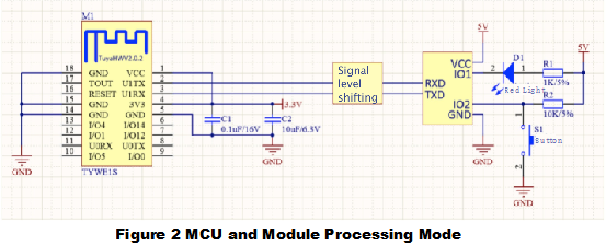
![TYWE1S Module & MCU serial communication instructions](https://images.tuyacn.com/smart/announcement/A_2AA.png)

### 2.Design specification <a href="#title-1-2.design-20specification" id="title-1-2.design-20specification"></a>

1. Module power supply consumption: 3.3V/100mA, instantaneous current(5us) 450mA. Proposed supply current≥300mA.
2. Power filter capacitor C1 & C2 should be distributed as close to the 3V3 pin as possible.
3. Serial port U1TX & U1RX are user interface. Default setting Baud rate: 9600, Data level: 8 bit, Stop bit: 1 bit, No check bit, No flow control. **If you need to use serial port 1 as a common IO port, please contact with the business.**
4. Serial port U0TX & U0RX are the interface related module printing, please don't link to user serial port

   **U0TX pin can't be used as an ordinary IO port, please suspend.** **if need to use U0RX pin as an ordinary IO port, please contact with the business.**
5. TOUT pin is voltage collection pin, can't be used as an ordinary IO port. **If idle, plesase suspend.**
6. IO 0 participates in the module for normal startup, when the power is on, this pin's level needs the high level for normal startup. For the export, a pull-up resistor is recommended. For the import, the input level should be considered. If idle, it can be suspended processing.
7. RESET pin is module hardware reset pin, effective under the low level. Without external circuitry, it can be directly connected to the IO port of MCU for use.
8. The module also needs the button and Wi-Fi status indicator. The button is used to clear network information of the module. The indicator is used to indicate the current status of the Wi-Fi module. If choose the module self-processing mode, refer to Diagram 1. If choose MCU & Module cooperative processing mode, refer to Diagram 2. Mode instructions can refer to "3.3 Query module work mode of MCU settings" in "Tuya general serial communication protocol".
9. If MCU supply voltage is 3.3V, circuit section about the signal level conversion in the reference diagram can be omitted.
10. Other idle pins can be suspended processing.
11. For Diagram 3, the antenna is susceptible to the shadow part of the package, don't wire and cover with copper, so as not to affect the antenna performance.
12. The exposed measuring point is located on the back of the module, as shown in Diagram 3 - The purple ring of TYWE1S recommended packaging. Please pay attention to avoidance when wiring. **Note: if need to recommend package, download it online or achieve it from the business.**

### 3.Antenna area instructions <a href="#title-2-3.antenna-20area-20instructions" id="title-2-3.antenna-20area-20instructions"></a>

Diagram 3 The shadow part is susceptible area for antenna, please don't wire and cover with copper. If the structure allows, please empty this area of PCB, so as not to affect the antenna performance.

![TYWE1S Module & MCU serial communication instructions](https://images.tuyacn.com/smart/announcement/A_3.png)

## TYWE3S Module & MCU serial communication instructions

### Typical Application diagram <a href="#title-0-typical-20application-20diagram" id="title-0-typical-20application-20diagram"></a>

Diagram 1 Module self-processing mode

![TYWE3S Module & MCU serial communication instructions](https://images.tuyacn.com/smart/announcement/A_BB1.png)

Diagram 2 MCU & Module cooperative processing mode

![TYWE3S Module & MCU serial communication instructions](https://images.tuyacn.com/smart/announcement/A_BB2.png)

### Design specification <a href="#title-1-design-20specification" id="title-1-design-20specification"></a>

1. Module power supply consumption：3.3V/100mA, instantaneous current(5us) 450mA. Proposed supply current≥300mA.
2. Power filter capacitor C1 & C2 should be distributed as close to VCC pin as possible.
3. Serial port TXD & RXD are communication ports. At startup, there will be a lot of module information data output. Default setting Baud rate: 9600, Data level: 8 bit, Stop bit: 1 bit, No check bit, No flow control.
4. ADC pin is voltage collection pin, can't be used as normal IO function. If idle, it needs to be suspended.
5. IO 0 participates in the module for normal startup, when the power is on, this pin's level needs the high level for normal startup. For the export, a pull-up resistor is recommended. For the import, the input level should be considered. If idle, it can be suspended processing.
6. IO 2 participates in the module for normal startup, when the power is on, this pin's level needs the high level for normal startup. The default mode is module debugging port, and data output is available on the upper current. If idle, it can be suspended processing.
7. IO 15 participates in the module for normal startup, When the power is on, the pin's level needs the low level for normal startup. You need to add a pull-down resistor to your pin.
8. RST pin is module hardware reset pin, reset under the low level. For use, it can be directly connected to MCU's IO port without external circuit.
9. **Please note that there is no pull-up resistor inside of IO16 when used**
10. The module also needs the button and Wi-Fi status indicator. The button is used to clear network information of the module. The indicator is used to indicate the current status of the Wi-Fi module. If choose the module self-processing mode, refer to Diagram 1. If choose MCU & Module cooperative processing mode, refer to Diagram 2. Mode instructions can refer to "3.3 Query module work mode of MCU settings" in "Tuya general serial communication protocol".
11. If MCU supply voltage is 3.3V, circuit section about the signal level conversion in the reference diagram can be omitted.
12. The pins 9-14 need to be suspended, and other idle pins also need to be suspended.
13. Figure 3 the ANTENNA part is the position of antenna, which is forbidden to cover the copper & wire. It's better to empty this area of PCB, so as not to affect the antenna performance.

### Packaging instructions <a href="#title-2-packaging-20instructions" id="title-2-packaging-20instructions"></a>

Diagram 3 TYWE3S boundary dimension

![TYWE3S Module & MCU serial communication instructions](https://images.tuyacn.com/smart/announcement/A_BB3.png)

**Note：if need recommended packaging, download from Internet or contact with the business.**

## Serial Port Communication Between the TYLC4 Module and MCU

### Typical Application Diagram <a href="#title-0-typical-20application-20diagram" id="title-0-typical-20application-20diagram"></a>

Figure 1-1 and Figure 1-2 show communication between the TYLC4 module and MCU in Wi-Fi module processing mode. Figure 1-3 and Figure 1-4 show communication between the module and MCU in cooperative processing mode.

S1 indicates the Wi-Fi module reset button, and LED1 indicates the Wi-Fi module status indicator. The following table lists the default mAppings between the LED1 status and working status of the Wi-Fi module.

| **LED1 Status** | **LED1 Display**                        | **Wi-Fi Module Status**    |
| --------------- | --------------------------------------- | -------------------------- |
| Blinks quickly  | Flashes on and off at 250 ms intervals  | SmartConfig mode           |
| Blinks slowly   | Flashes on and off at 1500 ms intervals | AP mode                    |
| Steady on       | Steady on                               | Connected to a router      |
| Steady off      | Steady off                              | Disconnected from a router |

Figure 1-1 Communication between the TYLC4 module and a 5 V MCU in Wi-Fi module processing mode
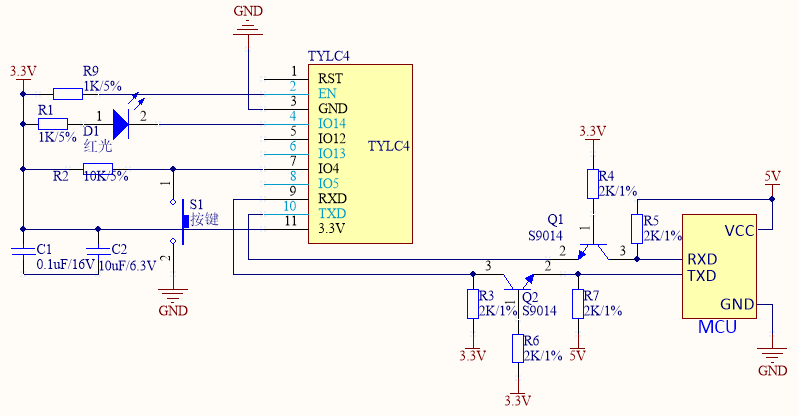
![Serial Port Communication Between the TYLC4 Module and MCU](https://images.tuyacn.com/smart_res/sample_module/tylc4_pic1_mcu.png)

Figure 1-2 Communication between the TYLC4 module and a 3.3 V MCU in Wi-Fi module processing mode
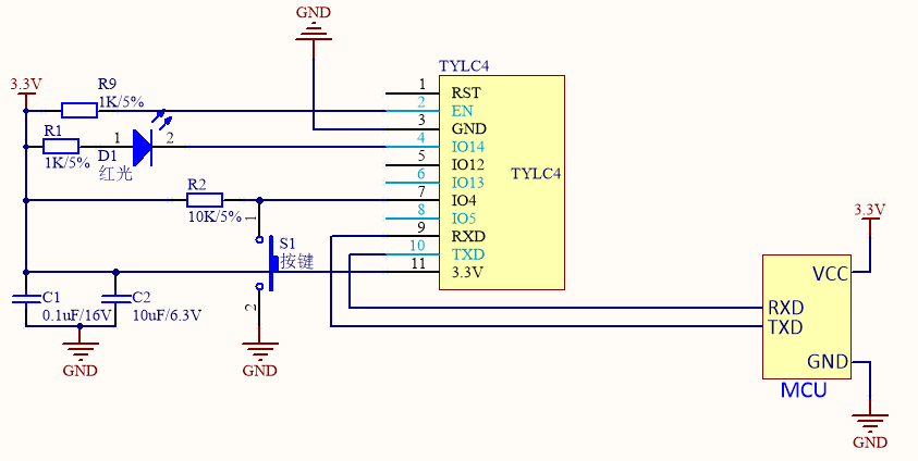
![Serial Port Communication Between the TYLC4 Module and MCU](https://images.tuyacn.com/smart_res/sample_module/tylc4_pic2_mcu.png)

Figure 1-3 Communication between the TYLC4 module and a 5 V MCU in cooperative processing mode
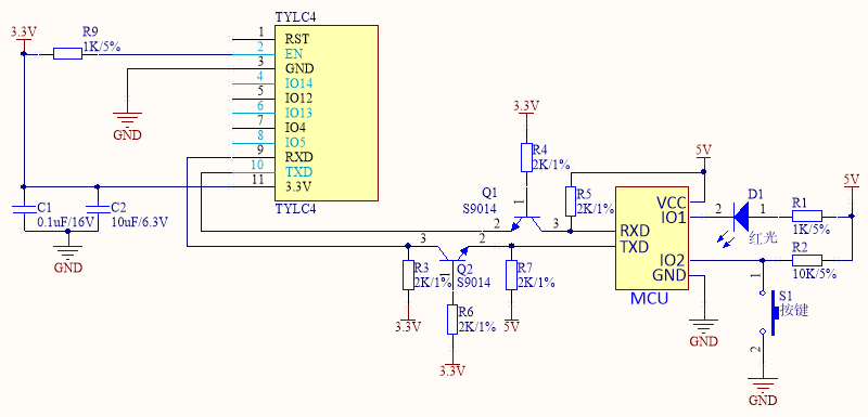
![Serial Port Communication Between the TYLC4 Module and MCU](https://images.tuyacn.com/smart_res/sample_module/tylc4_pic3_mcu.png)

Figure 1-4 Communication between the TYLC4 module and a 3.3 V MCU in cooperative processing mode
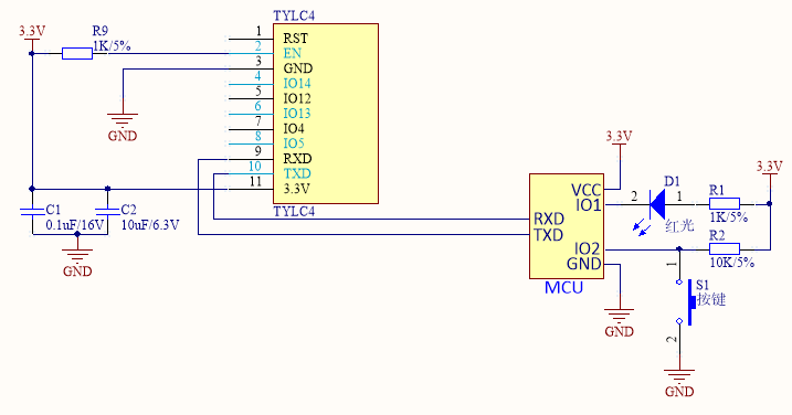
![Serial Port Communication Between the TYLC4 Module and MCU](https://images.tuyacn.com/smart_res/sample_module/tylc4_pic4_mcu.png)

### Design Description <a href="#title-1-design-20description" id="title-1-design-20description"></a>

1. The voltage and current for the Wi-Fi module to work properly are 3.3 V and 100 mA, respectively. It is recommended that the current be 300 mA or higher and that the total capacitance of external filter capacitors be more than 10 μF when the voltage is 3.3 V. When the Wi-Fi module is transmitting or receiving RF signals at 3.3 V, the current is increased by over 50%.
2. When designing the PCB layout, ensure that the filter capacitors C1 and C2 are as close to the VCC pin as possible.
3. The default settings for connections between the serial ports (TXD and RXD) and MCU are as follows:

   Baud rate: 9600

   Data bit: 8

   Stop bit: 1

   Parity bit: none

   Flow control: none

   For details, see *Tuya General Serial Port Communication Protocols*. When the Wi-Fi module is powered on, the TXD pin prints the module startup information. Skip the information during module startup. To use the serial port as a common I/O port, contact Tuya R\&D personnel.
4. The RST pin resets the module at low level. To use the RST pin, connect it to the I/O port of the MCU and low level input.
5. To use the module, you need a button and Wi-Fi status indicator.

   The button (S1 in Figure 1-1 and Figure 1-2) is used to clear the module's network configuration. You can use the smart product's network connection button.

   The indicator (LED1 in Figure 1-1 and Figure 1-2) indicates the working status of the Wi-Fi module or smart product.

   For details about the processing modes, see section 3.3 in *Tuya General Serial Port Communication Protocols*.
6. If the input voltage of the MCU is 3.3 V, skip signal level conversion in Figure 1-1 and Figure 1-3.
7. Other idle pins can be vacant.

## TYWE2S Module & MCU serial communication instructions

### Typical Application diagram <a href="#title-0-typical-20application-20diagram" id="title-0-typical-20application-20diagram"></a>

Diagram 1 MCU(3.3V) & Module cooperative processing mode

![TYWE2S Module & MCU serial communication instructions](https://airtake-public-data-1254153901.cos.ap-shanghai.myqcloud.com/goat/20200514/d79fb22c21134cfaae09a16e8495a836.png)

Diagram 2 MCU(5V) & Module cooperative processing mode

![TYWE2S Module & MCU serial communication instructions](https://airtake-public-data-1254153901.cos.ap-shanghai.myqcloud.com/goat/20200515/aa7d24afa8624690a1e42d90b529c467.png)

### Design specification <a href="#title-1-design-20specification" id="title-1-design-20specification"></a>

1. Module power supply consumption: 3.3V, instantaneous current (5us) 451mA. Proposed supply current≥600mA.
2. Power filter capacitor C1 & C2 should be distributed as close to the 3.3V pin as possible.C1 & C2≥10uF.
3. RESET pin is module hardware reset pin, effective under the low level. Without external circuitry, it can be directly connected to the IO port of MCU for use.

## TYJW1 Module & MCU serial communication instructions

### Typical Application diagram <a href="#title-0-typical-20application-20diagram" id="title-0-typical-20application-20diagram"></a>

Diagram 1 MCU(3.3V) & Module cooperative processing mode

![TYJW1 Module & MCU serial communication instructions](https://airtake-public-data-1254153901.cos.ap-shanghai.myqcloud.com/goat/20200515/e8a3a23d23154175b306cd06aebf1abe.png)!\[image.png]

Diagram 2 MCU(5V) & Module cooperative processing mode

![TYJW1 Module & MCU serial communication instructions](https://airtake-public-data-1254153901.cos.ap-shanghai.myqcloud.com/goat/20200515/6290460cc3b946c8b44bfdfee708f64f.png)

### Design specification <a href="#title-1-design-20specification" id="title-1-design-20specification"></a>

1. Module power supply consumption: 5V, instantaneous current(5us) 451mA. Proposed supply current≥600mA.
2. Power filter capacitor C1 & C2 should be distributed as close to the 5V pin as possible.C1 & C2≥10uF.
3. RESET pin is module hardware reset pin, effective under the low level. Without external circuitry, it can be directly connected to the IO port of MCU for use.

## TYJW2.0 Module & MCU serial communication instructions

### Typical Application diagram <a href="#title-0-typical-20application-20diagram" id="title-0-typical-20application-20diagram"></a>

Diagram 1 MCU(3.3V) & Module cooperative processing mode

![TYJW2.0 Module & MCU serial communication instructions](https://airtake-public-data.oss-cn-hangzhou.aliyuncs.com/goat/20200306/75362f47a26f47349e42c85e957aa5ef.png)

Diagram 2 MCU(5V) & Module cooperative processing mode

![TYJW2.0 Module & MCU serial communication instructions](https://airtake-public-data.oss-cn-hangzhou.aliyuncs.com/goat/20200306/ca15686569a64a498b59489b73fbe9f4.png)

### Design specification <a href="#title-1-design-20specification" id="title-1-design-20specification"></a>

1. Module power supply consumption: 5V, instantaneous current(5us) 451mA. Proposed supply current≥600mA.
2. Power filter capacitor C1 & C2 should be distributed as close to the 5V pin as possible.C1 & C2≥10uF.
3. RESET pin is module hardware reset pin, effective under the low level. Without external circuitry, it can be directly connected to the IO port of MCU for use.

## TYJW2.1 Module & MCU serial communication instructions

### Typical Application diagram <a href="#title-0-typical-20application-20diagram" id="title-0-typical-20application-20diagram"></a>

Diagram 1 MCU(3.3V) & Module cooperative processing mode

![TYJW2.1 Module & MCU serial communication instructions](https://airtake-public-data.oss-cn-hangzhou.aliyuncs.com/goat/20200306/27f4e15b0f5146968fde00ce245f6a12.png)

Diagram 2 MCU(5V) & Module cooperative processing mode

![TYJW2.1 Module & MCU serial communication instructions](https://airtake-public-data.oss-cn-hangzhou.aliyuncs.com/goat/20200306/c0942cfdc8d84c8196a9418cfc5b2735.png)

### Design specification <a href="#title-1-design-20specification" id="title-1-design-20specification"></a>

1. Module power supply consumption: 5V, instantaneous current(5us) 451mA. Proposed supply current≥600mA.
2. Power filter capacitor C1 & C2 should be distributed as close to the 5V pin as possible.C1 & C2≥10uF.
3. RESET pin is module hardware reset pin, effective under the low level. Without external circuitry, it can be directly connected to the IO port of MCU for use.

## TYJW2S-3.3V Module & MCU serial communication instructions

### Typical Application diagram <a href="#title-0-typical-20application-20diagram" id="title-0-typical-20application-20diagram"></a>

Diagram 1 MCU(3.3V) & Module cooperative processing mode

![TYJW2S-3.3V Module & MCU serial communication instructions](https://airtake-public-data.oss-cn-hangzhou.aliyuncs.com/goat/20200306/791ae69260d64e56841947903a2337e8.png)

Diagram 2 MCU(5V) & Module cooperative processing mode

![TYJW2S-3.3V Module & MCU serial communication instructions](https://airtake-public-data.oss-cn-hangzhou.aliyuncs.com/goat/20200306/4f4a7b05def646c1b7967654903872a4.png)

### Design specification <a href="#title-1-design-20specification" id="title-1-design-20specification"></a>

1. Module power supply consumption: 3.3V, instantaneous current(5us) 451mA. Proposed supply current≥600mA.
2. Power filter capacitor C1 & C2 should be distributed as close to the 3.3V pin as possible.C1 & C2≥10uF.
3. RESET pin is module hardware reset pin, effective under the low level. Without external circuitry, it can be directly connected to the IO port of MCU for use.

## TYJW2S-5V Module & MCU serial communication instructions

### Typical Application diagram <a href="#title-0-typical-20application-20diagram" id="title-0-typical-20application-20diagram"></a>

Diagram 1 MCU(3.3V) & Module cooperative processing mode

![TYJW2S-5V Module & MCU serial communication instructions](https://airtake-public-data.oss-cn-hangzhou.aliyuncs.com/goat/20200306/28d51ff4bd274bb0bff221de94164db2.png)

Diagram 2 MCU(5V) & Module cooperative processing mode

![TYJW2S-5V Module & MCU serial communication instructions](https://airtake-public-data.oss-cn-hangzhou.aliyuncs.com/goat/20200306/83b7af1b02804eaeb18b0684422b772d.png)

### Design specification <a href="#title-1-design-20specification" id="title-1-design-20specification"></a>

1. Module power supply consumption: 5V, instantaneous current(5us) 451mA. Proposed supply current≥600mA.
2. Power filter capacitor C1 & C2 should be distributed as close to the 5V pin as possible.C1 & C2≥10uF.
3. RESET pin is module hardware reset pin, effective under the low level. Without external circuitry, it can be directly connected to the IO port of MCU for use.

## WR1 Module & MCU serial communication instructions

### Typical Application diagram <a href="#title-0-typical-20application-20diagram" id="title-0-typical-20application-20diagram"></a>

Diagram 1 MCU(3.3V) & Module cooperative processing mode

![WR1 Module & MCU serial communication instructions](https://airtake-public-data.oss-cn-hangzhou.aliyuncs.com/goat/20200306/9dd07e25f9f14746a72261dd604d252b.png)

Diagram 2 MCU(5V) & Module cooperative processing mode

![WR1 Module & MCU serial communication instructions](https://airtake-public-data.oss-cn-hangzhou.aliyuncs.com/goat/20200306/3289e96bca2745db9f732e61bc1ee052.png)

### Design specification <a href="#title-1-design-20specification" id="title-1-design-20specification"></a>

1. Module power supply consumption: 3.3V,the maximum constant current295mA. Proposed supply current≥400mA.
2. Power filter capacitor C1 & C2 should be distributed as close to the 3.3V pin as possible.C1 & C2≥10uF.

## WR1E Module & MCU serial communication instructions

### Typical Application diagram <a href="#title-0-typical-20application-20diagram" id="title-0-typical-20application-20diagram"></a>

Diagram 1 MCU(3.3V) & Module cooperative processing mode

![WR1E Module & MCU serial communication instructions](https://airtake-public-data.oss-cn-hangzhou.aliyuncs.com/goat/20200306/98e770e2345940d38c4b03e129ace51b.png)

Diagram 2 MCU(5V) & Module cooperative processing mode

![WR1E Module & MCU serial communication instructions](https://airtake-public-data.oss-cn-hangzhou.aliyuncs.com/goat/20200306/71a98cff978e42e39e1ef0f77ba9014b.png)

### Design specification <a href="#title-1-design-20specification" id="title-1-design-20specification"></a>

1. Module power supply consumption: 3.3V,the maximum constant current295mA. Proposed supply current≥400mA.
2. Power filter capacitor C1 & C2 should be distributed as close to the 3.3V pin as possible.C1 & C2≥10uF.

## WR2 Module & MCU serial communication instructions

### Typical Application diagram <a href="#title-0-typical-20application-20diagram" id="title-0-typical-20application-20diagram"></a>

Diagram 1 MCU(3.3V) & Module cooperative processing mode

![WR2 Module & MCU serial communication instructions](https://airtake-public-data.oss-cn-hangzhou.aliyuncs.com/goat/20200306/a49a8a489ef64bcfb3877dcdc26e58ab.png)

Diagram 2 MCU(5V) & Module cooperative processing mode

![WR2 Module & MCU serial communication instructions](https://airtake-public-data.oss-cn-hangzhou.aliyuncs.com/goat/20200306/8d95f3d391804847a92d327bf0f685be.png)

### Design specification <a href="#title-1-design-20specification" id="title-1-design-20specification"></a>

1. Module power supply consumption: 3.3V,the maximum constant current295mA. Proposed supply current≥400mA.
2. Power filter capacitor C1 & C2 should be distributed as close to the 3.3V pin as possible.C1 & C2≥10uF.

## WR2E Module & MCU serial communication instructions

### Typical Application diagram <a href="#title-0-typical-20application-20diagram" id="title-0-typical-20application-20diagram"></a>

Diagram 1 MCU(3.3V) & Module cooperative processing mode

![WR2E Module & MCU serial communication instructions](https://airtake-public-data.oss-cn-hangzhou.aliyuncs.com/goat/20200306/9e5a81ac11f4488ab5b0baa98f0fbf34.png)

Diagram 2 MCU(5V) & Module cooperative processing mode

![WR2E Module & MCU serial communication instructions](https://airtake-public-data.oss-cn-hangzhou.aliyuncs.com/goat/20200306/566b00b1b58a464e85ae6803806ca5c8.png)

### Design specification <a href="#title-1-design-20specification" id="title-1-design-20specification"></a>

1. Module power supply consumption: 3.3V,the maximum constant current295mA. Proposed supply current≥400mA.
2. Power filter capacitor C1 & C2 should be distributed as close to the 3.3V pin as possible.C1 & C2≥10uF.

## WR3 Module & MCU serial communication instructions

### Typical Application diagram <a href="#title-0-typical-20application-20diagram" id="title-0-typical-20application-20diagram"></a>

Diagram 1 MCU(3.3V) & Module cooperative processing mode

![WR3 Module & MCU serial communication instructions](https://airtake-public-data.oss-cn-hangzhou.aliyuncs.com/goat/20200306/253f7957a2f64a9ab73d95a202ac396d.png)

Diagram 2 MCU(5V) & Module cooperative processing mode

![WR3 Module & MCU serial communication instructions](https://airtake-public-data.oss-cn-hangzhou.aliyuncs.com/goat/20200306/9e3dfbb1c43c401eb88835905cd3b091.png)

### Design specification <a href="#title-1-design-20specification" id="title-1-design-20specification"></a>

1. Module power supply consumption: 3.3V,the maximum constant current295mA. Proposed supply current≥400mA.
2. Power filter capacitor C1 & C2 should be distributed as close to the 3.3V pin as possible.C1 & C2≥10uF.

## WR3E Module & MCU serial communication instructions

### Typical Application diagram <a href="#title-0-typical-20application-20diagram" id="title-0-typical-20application-20diagram"></a>

Diagram 1 MCU(3.3V) & Module cooperative processing mode
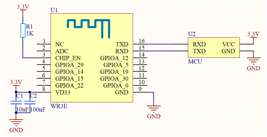
![WR3E Module & MCU serial communication instructions](https://airtake-public-data.oss-cn-hangzhou.aliyuncs.com/goat/20200306/63072426528040d484dd76f2931fa2ce.png)

Diagram 2 MCU(5V) & Module cooperative processing mode

![WR3E Module & MCU serial communication instructions](https://airtake-public-data.oss-cn-hangzhou.aliyuncs.com/goat/20200306/51b93fc32e744cf3941c750c5c027e6f.png)

### Design specification <a href="#title-1-design-20specification" id="title-1-design-20specification"></a>

1. Module power supply consumption: 3.3V,the maximum constant current295mA. Proposed supply current≥400mA.
2. Power filter capacitor C1 & C2 should be distributed as close to the 3.3V pin as possible.C1 & C2≥10uF.

## WR4 Module & MCU serial communication instructions

### Typical Application diagram <a href="#title-0-typical-20application-20diagram" id="title-0-typical-20application-20diagram"></a>

Diagram 1 MCU(3.3V) & Module cooperative processing mode

![WR4 Module & MCU serial communication instructions](https://airtake-public-data.oss-cn-hangzhou.aliyuncs.com/goat/20200306/60d68a0e8a5b49c3a322cffc907f0a2f.png)

Diagram 2 MCU(5V) & Module cooperative processing mode

![WR4 Module & MCU serial communication instructions](https://airtake-public-data.oss-cn-hangzhou.aliyuncs.com/goat/20200306/76f24553c84140adad009ff0e3fd9583.png)

### Design specification <a href="#title-1-design-20specification" id="title-1-design-20specification"></a>

1. Module power supply consumption: 3.3V,the maximum constant current295mA. Proposed supply current≥400mA.
2. Power filter capacitor C1 & C2 should be distributed as close to the 3.3V pin as possible.C1 & C2≥10uF.

## WRG1 Module & MCU serial communication instructions

### Typical Application diagram <a href="#title-0-typical-20application-20diagram" id="title-0-typical-20application-20diagram"></a>

Diagram 1 MCU(3.3V) & Module cooperative processing mode

![WRG1 Module & MCU serial communication instructions](https://airtake-public-data.oss-cn-hangzhou.aliyuncs.com/goat/20200309/fcd4a2c1f206471fb65f2f9fb491f033.png)

Diagram 2 MCU(5V) & Module cooperative processing mode

![WRG1 Module & MCU serial communication instructions](https://airtake-public-data.oss-cn-hangzhou.aliyuncs.com/goat/20200309/caacced267774c139471b836ae00bc92.png)

### Design specification <a href="#title-1-design-20specification" id="title-1-design-20specification"></a>

1. Module power supply consumption: 3.3V,the maximum constant current295mA. Proposed supply current≥400mA.
2. Power filter capacitor C1 & C2 should be distributed as close to the 3.3V pin as possible.C1 & C2≥10uF.

## WBR1 Module & MCU serial communication instructions

### Typical Application diagram <a href="#title-0-typical-20application-20diagram" id="title-0-typical-20application-20diagram"></a>

Diagram 1 MCU(3.3V) & Module cooperative processing mode

![WBR1 Module & MCU serial communication instructions](https://airtake-public-data-1254153901.cos.ap-shanghai.myqcloud.com/goat/20200629/776c99f19b5d461a90a165ca9ec32c5f.png)

Diagram 2 MCU(5V) & Module cooperative processing mode

![WBR1 Module & MCU serial communication instructions](https://airtake-public-data-1254153901.cos.ap-shanghai.myqcloud.com/goat/20200629/0091b173d52f47b7ba43e3b5bc31842c.png)

### Design specification <a href="#title-1-design-20specification" id="title-1-design-20specification"></a>

1. Module power supply consumption: 3.3V,the maximum instant current is 324mA. Proposed supply current≥500mA.
2. Power filter capacitor C1 & C2 should be distributed as close to the 3.3V pin as possible.C1 & C2≥10uF.

## WBR1D Module & MCU serial communication instructions

### Typical Application diagram <a href="#title-0-typical-20application-20diagram" id="title-0-typical-20application-20diagram"></a>

Diagram 1 MCU(3.3V) & Module cooperative processing mode

![WBR1D Module & MCU serial communication instructions](https://airtake-public-data-1254153901.cos.ap-shanghai.myqcloud.com/goat/20200629/2ff7a274d6ce482b96e7059754c41f4a.png)

Diagram 2 MCU(5V) & Module cooperative processing mode

![WBR1D Module & MCU serial communication instructions](https://airtake-public-data-1254153901.cos.ap-shanghai.myqcloud.com/goat/20200629/d40cacb9a80949f1934c99f31a953174.png)

### Design specification <a href="#title-1-design-20specification" id="title-1-design-20specification"></a>

1. Module power supply consumption: 3.3V,the maximum instant current is 392mA. Proposed supply current≥500mA.
2. Power filter capacitor C1 & C2 should be distributed as close to the 3.3V pin as possible.C1 & C2≥10uF.

## WBR2 Module & MCU serial communication instructions

### Typical Application diagram <a href="#title-0-typical-20application-20diagram" id="title-0-typical-20application-20diagram"></a>

Diagram 1 MCU(3.3V) & Module cooperative processing mode

![WBR2 Module & MCU serial communication instructions](https://airtake-public-data-1254153901.cos.ap-shanghai.myqcloud.com/goat/20200629/fced53c8d4da454989577ab125d541fc.png)

Diagram 2 MCU(5V) & Module cooperative processing mode

![WBR2 Module & MCU serial communication instructions](https://airtake-public-data-1254153901.cos.ap-shanghai.myqcloud.com/goat/20200629/eb5b2bb00a5f4e59a153f2cb0ecdc980.png)

### Design specificationi <a href="#title-1-design-20specificationi" id="title-1-design-20specificationi"></a>

1. Module power supply consumption: 3.3V,the maximum instant current is 324mA. Proposed supply current≥500mA.
2. Power filter capacitor C1 & C2 should be distributed as close to the 3.3V pin as possible.C1 & C2≥10uF.

## WBR2D Module & MCU serial communication instructions

### Typical Application diagram <a href="#title-0-typical-20application-20diagram" id="title-0-typical-20application-20diagram"></a>

Diagram 1 MCU(3.3V) & Module cooperative processing mode

![WBR2D Module & MCU serial communication instructions](https://airtake-public-data-1254153901.cos.ap-shanghai.myqcloud.com/goat/20200629/c899602875c441729c41937a3d2c71bd.png)

Diagram 2 MCU(5V) & Module cooperative processing mode

![WBR2D Module & MCU serial communication instructions](https://airtake-public-data-1254153901.cos.ap-shanghai.myqcloud.com/goat/20200629/32fbf2abb400434a9dfd4f9a1c0d9947.png)

### Design specification <a href="#title-1-design-20specification" id="title-1-design-20specification"></a>

1. Module power supply consumption: 3.3V,the maximum instant current is 392mA. Proposed supply current≥500mA.
2. Power filter capacitor C1 & C2 should be distributed as close to the 3.3V pin as possible.C1 & C2≥10uF.

## WBR3 Module & MCU serial communication instructions

### Typical Application diagram <a href="#title-0-typical-20application-20diagram" id="title-0-typical-20application-20diagram"></a>

Diagram 1 MCU(3.3V) & Module cooperative processing mode

![WBR3 Module & MCU serial communication instructions](https://airtake-public-data-1254153901.cos.ap-shanghai.myqcloud.com/goat/20200629/037a6e5c64114f6bbbaab3cb421c5598.png)

Diagram 2 MCU(5V) & Module cooperative processing mode
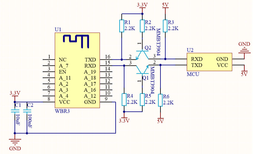
![WBR3 Module & MCU serial communication instructions](https://airtake-public-data-1254153901.cos.ap-shanghai.myqcloud.com/goat/20200629/e648ed6f5bcd48bb968dbb5b0a59b4bc.png)

### Design specification <a href="#title-1-design-20specification" id="title-1-design-20specification"></a>

1. Module power supply consumption: 3.3V,the maximum instant current is 324mA. Proposed supply current≥500mA.
2. Power filter capacitor C1 & C2 should be distributed as close to the 3.3V pin as possible.C1 & C2≥10uF.

## WBR3D Module & MCU serial communication instructions

### Typical Application diagram <a href="#title-0-typical-20application-20diagram" id="title-0-typical-20application-20diagram"></a>

Diagram 1 MCU(3.3V) & Module cooperative processing mode

![WBR3D Module & MCU serial communication instructions](https://airtake-public-data-1254153901.cos.ap-shanghai.myqcloud.com/goat/20200629/080938200e13441db300aee16e445b73.png)

Diagram 2 MCU(5V) & Module cooperative processing mode

![WBR3D Module & MCU serial communication instructions](https://airtake-public-data-1254153901.cos.ap-shanghai.myqcloud.com/goat/20200629/f22b788279904e8596311c1be654bcb3.png)

### Design specification <a href="#title-1-design-20specification" id="title-1-design-20specification"></a>

1. Module power supply consumption: 3.3V,the maximum instant current is 392mA. Proposed supply current≥500mA.
2. Power filter capacitor C1 & C2 should be distributed as close to the 3.3V pin as possible.C1 & C2≥10uF.


# Software Reference Wi-Fi

### &#x20;<a href="#title-2-3-e3-80-81protocol-20details" id="title-2-3-e3-80-81protocol-20details"></a>


# Tuya Cloud Universal Serial Port Access Protocol

| Protocol version | Date     |
| ---------------- | -------- |
| 1.2.3            | 20200521 |

### 1、Serial communication conventions <a href="#title-0-1-e3-80-81serial-20communication-20conventions" id="title-0-1-e3-80-81serial-20communication-20conventions"></a>

Baud rate: 9600/115200

Data bits: 8

Parity: None

Stop bits: 1

Data flow control: None

MCU: User control board control chip, connected with Tuya module through serial port.

### 2、Frame Format Description <a href="#title-1-2-e3-80-81frame-20format-20description" id="title-1-2-e3-80-81frame-20format-20description"></a>

| Field        | Length (byte) | Description                                                     |
| ------------ | ------------- | --------------------------------------------------------------- |
| Frame Header | 2             | Fixed at 0x55aa                                                 |
| Version      | 1             | Upgrade and Expansion                                           |
| Command word | 1             | Specific frame type                                             |
| Data Length  | 2             | Big Endian                                                      |
| Data         | N             |                                                                 |
| Checksum     | 1             | Byte-sum results from the beginning of the frame, 256 remainder |

Explanation:

* All data larger than 1 byte is transmitted in big-endian mode.
* Under normal circumstances, the same command word is used to send and receive synchronization mechanism, that is, one party sends a command and the other responds. If the sender does not receive the correct response packet after timeout, the timeout is transmitted, as shown in the figure below:

![Tuya Cloud Universal Serial Port Access Protocol](https://airtake-public-data-1254153901.cos.ap-shanghai.myqcloud.com/goat/20200624/933fc92a75bf4717a1287be0a1ef4dbb.png)

Note: The specific communication method is subject to the "Protocol Details" section.

* The module control command is issued and the MCU status is reported in asynchronous mode. Assuming that the module control command is issued with the "command word" as x and the MCU status is reported with the "command word" as y, as follows:
* Module control command is issued:

  ![Tuya Cloud Universal Serial Port Access Protocol](https://airtake-public-data-1254153901.cos.ap-shanghai.myqcloud.com/goat/20200624/4ddfb2866f75463895a6e7417602ff09.png)
* MCU status report:

  ![Tuya Cloud Universal Serial Port Access Protocol](https://airtake-public-data-1254153901.cos.ap-shanghai.myqcloud.com/goat/20200624/6429ceebfd43445eb96c39199e6d56e1.png)

### 3、Protocol details <a href="#title-2-3-e3-80-81protocol-20details" id="title-2-3-e3-80-81protocol-20details"></a>

### 3.1、Heartbeat detection

Explanation:

1. After the WIFI module is powered on, it periodically sends heartbeats at 15s intervals. If no response is received from the MCU within the timeout period (3s), the MCU is considered offline.
2. The MCU can also periodically check whether the module is working properly based on this heartbeat. If the module is issued without a heartbeat, the MCU can reset the WIFI module through the hardware reset pin provided by the module.

Module sends:

| Field        | Length (byte) | Description                                                     |
| ------------ | ------------- | --------------------------------------------------------------- |
| Frame Header | 2             | 0x55aa                                                          |
| Version      | 1             | 0x00                                                            |
| Command Word | 1             | 0x00                                                            |
| Data length  | 2             | 0x0000                                                          |
| Data         | 0             | None                                                            |
| Checksum     | 1             | Byte-sum results from the beginning of the frame, 256 remainder |

Example: 0x55aa 00 00 0000 ff

The MCU returns:

| Field        | Length (byte) | Description                                                                                                                                                                        |
| ------------ | ------------- | ---------------------------------------------------------------------------------------------------------------------------------------------------------------------------------- |
| Frame Header | 2             | 0x55aa                                                                                                                                                                             |
| Version      | 1             | 0x03                                                                                                                                                                               |
| Command Word | 1             | 0x00                                                                                                                                                                               |
| Data length  | 2             | 0x0001                                                                                                                                                                             |
| Data         | 1             | 0x00: The first heartbeat return value after the MCU restarts, sent only once, used by the module to determine whether the MCU restarts during the work process. Return this value |
| Checksum     | 1             | Byte-sum results from the beginning of the frame, 256 remainder                                                                                                                    |

Example: 0x55aa 03 00 0001 00 03 (MCU returns for the first time)

0x55aa 03 00 0001 01 04 (except for the first time, return normally)

### 3.2、Query Product Information

Explanation:

1. Product ID: Corresponds to the Tuya Developer Platform PID (product identification), which is generated by the Tuya Cloud Developer Platform and used to record product-related information in the cloud.
2. Product information consists of product ID and MCU software version
3. MCU software version number format definition: in dotted decimal form, "x.x.x" (0 \ <= x \ <= 99), x is a decimal number

Module sends:

| Field        | Length (byte) | Description                                                     |
| ------------ | ------------- | --------------------------------------------------------------- |
| Frame Header | 2             | 0x55aa                                                          |
| Version      | 1             | 0x00                                                            |
| Command Word | 1             | 0x01                                                            |
| Data length  | 2             | 0x0000                                                          |
| Data         | 0             | None                                                            |
| Checksum     | 1             | Byte-sum results from the beginning of the frame, 256 remainder |

Example: 0x55aa 00 01 0000 00

The MCU returns:

| Field        | Length (byte) | Description                                                                  |
| ------------ | ------------- | ---------------------------------------------------------------------------- |
| Frame Header | 2             | 0x55aa                                                                       |
| Version      | 1             | 0x03                                                                         |
| Command Word | 1             | 0x01                                                                         |
| Data Length  | 2             | N                                                                            |
| Data         | N             | {“p”:”AIp08kLIftb8x2x0”,“v”:”1.0.0”,”m”:1,”mt”:10,”n”:0,”ir”:”5.12”,”low”:0} |
| Checksum     | 1             | Byte-sum results from the beginning of the frame, 256 remainder              |

Example: {“p”:”AIp08kLIftb8x2x0”,“v”:”1.0.0”,”m”:1,”mt”:10,”n”:0,”ir”:”5.12”,”low”:0}

Product information field description:

1\) p means the product ID is AIp08kLIftb8x2x0, which is the product ID created by the user on the Tuya IOT platform.

2\) v indicates that the MCU version is 1.0.0, and the MCU version number format needs to be defined in the format of x.x.x

3\) m indicates the working mode of the module: 0-normal distribution network working mode, 1-overtime distribution network working mode, 2-anti-mistouch working mode.

**normal distribution network working mode:** After leaving the factory, the module has been in the state of network distribution and has been maintained.

**overtime distribution network working mode:** The module is in a non-distribution state after it is powered on from the factory and requires the MCU to send a reset command before entering the corresponding distribution mode The device will enter the non-distribution state again after the module is in the distribution state for three minutes without the user distributing the module. The command will re-enter the network configuration mode.

**anti-mistouch working mode:** After the module is configured by the user locally (the MCU sends a reset command), the device is in the network to be configured If the status is not configured for three minutes, it will automatically restore the user's network connection before reset. The device breaks abnormally halfway after local reset Power on will also automatically restore the user's network connection before reset. In this mode, only when the device is moved from the APP by the user Except for the device, it will not record the last user's network connection and reconnect. This mode is for users who need local reset The needs of the scene.

4\) mt field (optional): Set the state switching time of safe mode and anti-mistouch mode, without uploading this field, follow the old mechanism Three minutes processing, can support the set time range: 3 minutes \~ 10 minutes.

5\) n field (optional): indicates the network configuration mode of the mode. Without this field, the traditional two-network mode switching mode is maintained: 0-smartconfig & AP coexistence distribution network mode The module supports both AP connection and EZ distribution without user switching. For the corresponding distribution status package, see 1-Only AP configuration mode   In this mode, the product can only be configured through AP connection.

6\) ir field (optional): enable the infrared function of the module and inform the module that the infrared transceiver pins use those IO ports. Without this field, the infrared capability is turned off by default 5.12: the infrared transmit pin is IO5, and the infrared receive pin is IO12. Note that if the module self-processing mode is used in the working mode, do not repeat it with the IO port set according to the WIFI indicator light. Part of the module cross-group IO setting, you need to add 32 to the base of the setting group IO, PB20 set the serial number to 20+32. The infrared sending pin needs to use PWM resources, and the receiving needs to use IO interrupt. The specific module supports the IO port reference module information.

7\) low field (optional): Whether the module is turned on to maintain a low-power mode for long connection, without this field, the low-power mode is turned off by default. For some products, when there is no network control, the average power consumption of the module needs to be lower than 15MA under the connection of the module to maintain and route. Through this field, we can open the ability of the module. After the dual-mode module turns on this function, the module has only the Bluetooth distribution function, and the Bluetooth control will be turned off. Products that do not require power consumption do not need to care about this field. 0-turn off low power mode 1-Turn on the module low power mode

### 3.3、Query MCU and set the module's working mode

Explanation:

1. The module working mode is mainly for how to indicate the working status of WIFI and how to reset WIFI. There are mainly two cases:

   a. MCU cooperates with the module, that is, the module notifies the MCU through the serial port The current working status of WIFI is supported by the MCU; the MCU detects the need to reset the WIFI and informs the module to reset the WIFI through the serial port.

   b. Module self-processing: The working status of the WIFI module drives the LED status display through the WIFI GPIO pins; WIFI reset is handled by detecting the GPIO input requirements. The module's self-processing WIFI reset method is: WIFI detects the GPIO entry low level for more than 5s to trigger Wi-Fi reset. The GPIO pins used by the indicators and buttons are configured by the following commands.

Module sends:

| Field        | Length (byte) | Description                                                     |
| ------------ | ------------- | --------------------------------------------------------------- |
| Frame Header | 2             | 0x55aa                                                          |
| Version      | 1             | 0x00                                                            |
| Command Word | 1             | 0x02                                                            |
| Data length  | 2             | 0x0000                                                          |
| Data         | 0             | None                                                            |
| Checksum     | 1             | Byte-sum results from the beginning of the frame, 256 remainder |

Example: 0x55aa 00 02 0000 01

The MCU returns:

| Field        | Length (byte) | Description                                                                                                                                                                                                                                                        |
| ------------ | ------------- | ------------------------------------------------------------------------------------------------------------------------------------------------------------------------------------------------------------------------------------------------------------------ |
| Frame Header | 2             | 0x55aa                                                                                                                                                                                                                                                             |
| Version      | 1             | 0x03                                                                                                                                                                                                                                                               |
| Command Word | 1             | 0x02                                                                                                                                                                                                                                                               |
| Data length  | 2             | <p>0x0000 / 0x0002<br>0x0000: Instruct the module to work in "MCU and module cooperative processing" mode. The MCU must implement the functions mentioned in the "Description" above.<br>0x0002: Instruct the module to work in "module self-processing" mode.</p> |
| Data         | 0/2           | The data length is 2: the first byte is the WIFI status indication GPIO sequence number; the second byte is the WIFI reset button GPIO sequence number                                                                                                             |
| Checksum     | 1             | Byte-sum results from the beginning of the frame, 256 remainder                                                                                                                                                                                                    |

Example: 0x55aa 03 02 0000 04 (MCU and module work together)

0x55aa 03 02 0002 0c0d1f (module self-processing, indicator 0x0c: GPIO12, reset button 0x0d: GPIO13)

### 3.4、Report device networking status

| Device Networking Status | Description                                        | Status Values |
| ------------------------ | -------------------------------------------------- | ------------- |
| Status 1                 | smartconfig configuration status                   | 0x00          |
| State 2                  | AP configuration state                             | 0x01          |
| State 3                  | WIFI is configured but not connected to the router | 0x02          |
| State 4                  | WIFI is configured and connected to the router     | 0x03          |
| Status 5                 | Connected to the router and connected to the cloud | 0x04          |
| State 6                  | WIFI device is in low power mode                   | 0x05          |
| State 7                  | WIFI device is in smartconfig\&AP mode             | 0x06          |

Explanation:

1. Device networking status: 1 smartconfig configuration status 2 AP configuration status 3 WIFI configured successfully but not connected to the router 4 WIFI configured successfully and connected to the router 5 The device is connected to a router and connected to the cloud. The corresponding LED displays of the "module self-processing" working mode are: 1 250ms flashing interval; 2 1500ms flashing interval; 3 long dark state; 4 or 5 long bright state
2. When the module detects the process of MCU restart or MCU disconnection and then online, it will actively send WIFI status to MCU
3. When the WIFI status of the module changes, it will actively send the WIFI status to the MCU
4. If the module working mode is set to "module self-processing", the MCU does not need to implement the protocol

Module sends:

| Field        | Length (byte) | Description                                                                                                                                                        |
| ------------ | ------------- | ------------------------------------------------------------------------------------------------------------------------------------------------------------------ |
| Frame Header | 2             | 0x55aa                                                                                                                                                             |
| Version      | 1             | 0x00                                                                                                                                                               |
| Command Word | 1             | 0x03                                                                                                                                                               |
| Data length  | 2             | 0x0001                                                                                                                                                             |
| Data         | 1             | <p>Indicate the working status of WIFI:<br>0x00: State 1<br>0x01: State 2<br>0x02: State 3<br>0x03: State 4<br>0x04: State 5<br>0x05: State 6<br>0x06: State 7</p> |
| Checksum     | 1             | Byte-sum results from the beginning of the frame, 256 remainder                                                                                                    |

Example: 0x55aa 00 03 0001 00 03

The MCU returns:

| Field        | Length (byte) | Description                                                     |
| ------------ | ------------- | --------------------------------------------------------------- |
| Frame Header | 2             | 0x55aa                                                          |
| Version      | 1             | 0x03                                                            |
| Command Word | 1             | 0x03                                                            |
| Data length  | 2             | 0x0000                                                          |
| Data         | 0             | None                                                            |
| Checksum     | 1             | Byte-sum results from the beginning of the frame, 256 remainder |

Example: 0x55aa 03 03 0000 05

### 3.5、Reset WIFI

Explanation:

1. Reset WIFI status transition as shown below:
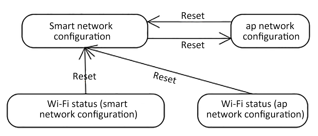
![Tuya Cloud Universal Serial Port Access Protocol](https://images.tuyacn.com/smart/aircondition/mcu-dev7.png)

The module's self-processing WIFI reset method is: WIFI detects the GPIO entry low level for more than 5s to trigger Wi-Fi reset.

1. If the module working mode is set to "module self-processing", the MCU does not need to implement the protocol

MCU sends:

| Field        | Length (byte) | Description                                                     |
| ------------ | ------------- | --------------------------------------------------------------- |
| Frame Header | 2             | 0x55aa                                                          |
| Version      | 1             | 0x03                                                            |
| Command Word | 1             | 0x04                                                            |
| Data length  | 2             | 0x0000                                                          |
| Data         | 0             | None                                                            |
| Checksum     | 1             | Byte-sum results from the beginning of the frame, 256 remainder |

Example: 0x55aa 03 04 0000 06

The module returns:

| Field        | Length (byte) | Description                                                     |
| ------------ | ------------- | --------------------------------------------------------------- |
| Frame Header | 2             | 0x55aa                                                          |
| Version      | 1             | 0x00                                                            |
| Command Word | 1             | 0x04                                                            |
| Data length  | 2             | 0x0000                                                          |
| Data         | 0             | None                                                            |
| Checksum     | 1             | Byte-sum results from the beginning of the frame, 256 remainder |

Example: 0x55aa 00 04 0000 03

### 3.6、Reset WIFI-select configuration mode

Explanation:

1. Compared to “Resetting WIFI” in section 3.5, this frame provides the MCU to selectively choose the configuration mode after resetting WIFI according to its own needs.
2. MCU access users can selectively implement the protocol
3. If the module working mode is set to "module self-processing", the MCU does not need to implement the protocol

MCU sends:

| Field        | Length (byte) | Description                                                                            |
| ------------ | ------------- | -------------------------------------------------------------------------------------- |
| Frame Header | 2             | 0x55aa                                                                                 |
| Version      | 1             | 0x03                                                                                   |
| Command Word | 1             | 0x05                                                                                   |
| Data length  | 2             | 0x0001                                                                                 |
| Data         | 1             | <p>0x00: Enter smartconifg configuration mode<br>0x01: Enter AP configuration mode</p> |
| Checksum     | 1             | Byte-sum results from the beginning of the frame, 256 remainder                        |

Example: 0x55aa 03 05 0001 00 08, enter smartconfig configuration mode

The module returns:

| Field        | Length (byte) | Description                                                     |
| ------------ | ------------- | --------------------------------------------------------------- |
| Frame Header | 2             | 0x55aa                                                          |
| Version      | 1             | 0x00                                                            |
| Command Word | 1             | 0x05                                                            |
| Data length  | 2             | 0x0000                                                          |
| Data         | 0             | None                                                            |
| Checksum     | 1             | Byte-sum results from the beginning of the frame, 256 remainder |

Example: 0x55aa 00 05 0000 04

### 3.7、Command issued

Explanation:

1. The datapoint command / status data unit is as follows:

| Data Section | Length (byte) | Explanation                                                                                                                   |       |                                     |                                                                |
| ------------ | ------------- | ----------------------------------------------------------------------------------------------------------------------------- | ----- | ----------------------------------- | -------------------------------------------------------------- |
| dpid         | 1             | datapoint serial number                                                                                                       |       |                                     |                                                                |
| type         | 1             | Corresponds to the specific data type of a datapoint on the open platform, identified by the following "representation value" |       |                                     |                                                                |
|              |               | Type                                                                                                                          | Value | Length (bytes)                      |                                                                |
|              |               | raw                                                                                                                           | 0x00  | N                                   | Corresponds to raw datapoint (module transparent transmission) |
|              |               | bool                                                                                                                          | 0x01  | 1                                   | value range: 0x00 / 0x01                                       |
|              | value         | 0x02                                                                                                                          | 4     | Corresponds to int type, big-endian |                                                                |
|              |               | string                                                                                                                        | 0x03  | N                                   | corresponds to a specific string                               |
|              |               | enum                                                                                                                          | 0x04  | 1                                   | Enumeration type, range 0-255                                  |
|              |               | bitmap                                                                                                                        | 0x05  | 1/2/4                               |                                                                |
| len          | 2             | Number of bytes corresponding to length                                                                                       |       |                                     |                                                                |
| value        | 1/2/4 / N     | hex indicates that big-endian transmission is used for more than 1 byte                                                       |       |                                     |                                                                |

1. Datapoint command / status data unit except "raw" type, other types are "obj" type datapoint
2. The "command delivery" may contain multiple datapoint "command data units"
3. "Command Issue" is an asynchronous processing protocol, corresponding to the "status report" of the MCU's datapoint

Module sends:

| Field        | Length (byte) | Description                                                     |
| ------------ | ------------- | --------------------------------------------------------------- |
| Frame Header | 2             | 0x55aa                                                          |
| Version      | 1             | 0x00                                                            |
| Command Word | 1             | 0x06                                                            |
| Data length  | 2             | Depends on Command Data Unit type and number                    |
| Data         | N             | "3.7.1 Command Data Unit" Group                                 |
| Checksum     | 1             | Byte-sum results from the beginning of the frame, 256 remainder |

Example: The system switch corresponds to DP No. 3, using a bool-type variable, and the power-on value is 1.

0x55aa 00 06 0005 03 01 0001 01 10

### 3.8、Status report

Explanation:

1. For details of the datapoint status data unit, see "Section 3.7"
2. "State Report" is an asynchronous processing protocol. There are three types of "State Report" trigger mechanisms:

   a. When the MCU receives the "command to issue a processing frame, the corresponding datapoint command is correctly executed, and then the changed datapoint status is sent to the module through the" status report "frame;

   b. The MCU actively detects a change in the datapoint and sends the changed datapoint status to the module;

   c. When the MCU receives the status query frame of “3.9”, it sends all datapoint status to the module.
3. The "status report" may contain multiple datapoint "command data units"

MCU sends:

| Field        | Length (byte) | Description                                                     |
| ------------ | ------------- | --------------------------------------------------------------- |
| Frame Header | 2             | 0x55aa                                                          |
| Version      | 1             | 0x03                                                            |
| Command Word | 1             | 0x07                                                            |
| Data length  | 2             | Depends on the type and number of Status Data Units             |
| Data         | N             | "3.7.1 Status Data Unit" Group                                  |
| Checksum     | 1             | Byte-sum results from the beginning of the frame, 256 remainder |

Example: The humidity corresponds to No. 5 DP, using a valve-type variable, and the humidity is 30 ° C

0x55aa 03 07 0008 05 02 0004 0000001e 3a

### 3.9、Status query

Explanation:

1. "Status query" is an asynchronous processing protocol, which is mainly used by the module to query the status of all "obj" type datapoints of the MCU. When the MCU receives this frame, it reports the datapoint status through the "3.8" status report frame
2. There are two main timings for sending "Status Query":

   a. The module is powered on for the first time, and after the connection is established with the MCU through the heartbeat, the query is sent;

   b. During the module's work, it is detected that the MCU restarts or goes offline and then goes online. The query is sent.

Module sends:

| Field        | Length (byte) | Description                                                     |
| ------------ | ------------- | --------------------------------------------------------------- |
| Frame Header | 2             | 0x55aa                                                          |
| Version      | 1             | 0x00                                                            |
| Command Word | 1             | 0x08                                                            |
| Data length  | 2             | 0x0000                                                          |
| Data         | 0             | None                                                            |
| Checksum     | 1             | Byte-sum results from the beginning of the frame, 256 remainder |

Example: 0x55aa 00 08 0000 07

### 3.10、MCU upgrade service

Explanation:

1. When to upgrade the customer The Tuya IoT platform ’s own product page configuration related upgrade options are triggered. The module is only used as a data transmission channel to support MCU upgrades and does not perform any analysis of the data content.
2. At present, the MCU upgrade of Tuya platform supports the following four configuration methods:

   a.App reminder upgrade: In this upgrade method, users will receive the pop-up window of the upgrade reminder every time they enter the device control panel. Whether to confirm the upgrade is confirmed by the user in the App.

   b.App silent upgrade: This upgrade method App will not have any pop-up window. The firmware will automatically detect the upgrade within one minute after the firmware is powered on. It will automatically start pulling related upgrade packages if it finds a higher version upgrade package. After power-on, the module will go to the cloud to check whether there is an upgrade package configuration at an interval of 24 hours.

   c.App forced upgrade:In this upgrade method, there will be an upgrade reminder pop-up on the App side. If the user does not confirm the upgrade, the user cannot use the control panel of this product normally.

   d.App detection upgrade: this upgrade method App sideThere will not be any pop-up window for upgrade reminder. The user must click on the App to check the relevant firmware version by himself. If there is a higher firmware configuration, the upgrade prompt message will be displayed.
3. MCU upgrade related flowchart:

   After the WIFI module sends all the upgrade packages, resend the 01 command word (3.2 query product information). The MCU needs to reply the software version number in the product information with the updated MCU version number in one minute. The version number needs to be configured in Tuya's background. Upgraded version numbers remain the same.

![Tuya Cloud Universal Serial Port Access Protocol](https://airtake-public-data-1254153901.cos.ap-shanghai.myqcloud.com/goat/20200624/6c0a8441f00b463f905deaa2cec51c06.png)

**3.10.1、Upgrade started (upgrade package size notification)**

Explanation:

1. The upgrade startup method includes automatic and manual upgrades. When it is in automatic upgrade, the module detects that the cloud MCU has a newer version of firmware, then it automatically starts the interaction process with the MCU upgrade package; when it is in manual upgrade, it is determined by the App that the module inspires the interaction process with the MCU upgrade package

Module sends:

| Field        | Length (byte) | Description                                                     |
| ------------ | ------------- | --------------------------------------------------------------- |
| Frame Header | 2             | 0x55aa                                                          |
| Version      | 1             | 0x00                                                            |
| Command Word | 1             | 0x0a                                                            |
| Data length  | 2             | 0x0004                                                          |
| Data         | 4             | Firmware Package Bytes, unsigned int, Big Endian                |
| Checksum     | 1             | Byte-sum results from the beginning of the frame, 256 remainder |

Example: 0x55aa 00 0a 0004 00006800 75 (the firmware package length is 26624, which is 26KB)

The MCU returns:

| Field        | Length (byte) | Description                                                                                                                       |
| ------------ | ------------- | --------------------------------------------------------------------------------------------------------------------------------- |
| Frame Header | 2             | 0x55aa                                                                                                                            |
| Version      | 1             | 0x03                                                                                                                              |
| Command Word | 1             | 0x0a                                                                                                                              |
| Data length  | 2             | 0x0001                                                                                                                            |
| Data         | 1             | <p>Upgrading packet transfer size:<br>0x00: default 256byte (compatible with old firmware)<br>0x01: 512byte<br>0x02: 1024byte</p> |
| Checksum     | 1             | Byte-sum results from the beginning of the frame, 256 remainder                                                                   |

Example: 0x55aa 03 0a 0001 00 0d

**3.10.2、Upgrade package transmission**

Explanation:

1. Upgrade packet transmission data format: packet offset (unsigned short) + packet data
2. If the MCU receives the frame data length of 4 and the packet offset > = firmware size, the packet transmission ends.

Module sends:

| Field        | Length (byte) | Description                                                                      |
| ------------ | ------------- | -------------------------------------------------------------------------------- |
| Frame Header | 2             | 0x55aa                                                                           |
| Version      | 1             | 0x00                                                                             |
| Command Word | 1             | 0x0b                                                                             |
| Data length  | 2             | 0x0004 + Data packet length                                                      |
| Data         | N             | The first four bytes, fixed at the packet offset, followed by the packet content |
| Checksum     | 1             | Byte-sum results from the beginning of the frame, 256 remainder                  |

example:

The file size to be upgraded is 530Byte, (the last packet of data may not be returned)

(1) The first packet of data, the packet offset is 0x00000000, and the packet length is 256

0x55aa 00 0b 0104 00000000 xx ... xx XX

(2) The second packet of data, the packet offset is 0x00000100, and the packet length is 256

0x55aa 00 0b 0104 00000100 xx ... xx XX

(3) The third packet of data, the packet offset is 0x00000200, and the packet length is 18

0x55aa 00 0b 0016 00000200 xx ... xx XX

(4) The last packet, the packet offset is 0x00000212, and the data packet length is 0

0x55aa 00 0b 0004 00000212 xx ... xx XX

The MCU returns:

| Field        | Length (byte) | Description                                                     |
| ------------ | ------------- | --------------------------------------------------------------- |
| Frame Header | 2             | 0x55aa                                                          |
| Version      | 1             | 0x03                                                            |
| Command Word | 1             | 0x0b                                                            |
| Data length  | 2             | 0x0000                                                          |
| Data         | 0             | None                                                            |
| Checksum     | 1             | Byte-sum results from the beginning of the frame, 256 remainder |

Example: 0x55aa 03 0b 0000 0d

### 3.11、Get System Time (GMT)

Explanation:

(1) Green Time does not include time zone and daylight saving time factors, and is an international standard time reference.

(2) When the local time stamp is calibrated before the module is connected to the network, it will return success with valid time data.

MCU sends:

| Field        | Length (byte) | Description                                                     |
| ------------ | ------------- | --------------------------------------------------------------- |
| Frame Header | 2             | 0x55aa                                                          |
| Version      | 1             | 0x03                                                            |
| Command Word | 1             | 0x0c                                                            |
| Data length  | 2             | 0x0000                                                          |
| Data         | 0             | None                                                            |
| Checksum     | 1             | Byte-sum results from the beginning of the frame, 256 remainder |

Example: 0x55aa 03 0c 0000 0e

The module returns:

| Field        | Length (byte) | Description                                                                                                                                                                                                                                                                                                                                                                                                             |
| ------------ | ------------- | ----------------------------------------------------------------------------------------------------------------------------------------------------------------------------------------------------------------------------------------------------------------------------------------------------------------------------------------------------------------------------------------------------------------------- |
| Frame Header | 2             | 0x55aa                                                                                                                                                                                                                                                                                                                                                                                                                  |
| Version      | 1             | 0x00                                                                                                                                                                                                                                                                                                                                                                                                                    |
| Command Word | 1             | 0x0c                                                                                                                                                                                                                                                                                                                                                                                                                    |
| Data length  | 2             | 0x0007                                                                                                                                                                                                                                                                                                                                                                                                                  |
| Data         | 7             | <p>Data length is 7 bytes:<br>Data \[0] is the time success flag, 0 means failure, 1 means success<br>Data \[1] means year, 0x00 means 2000 Year<br>Data \[2] is the month, starting from 1 to 12<br>Data \[3] is the date, starting from 1 to 31<br>Data \[4] is the clock, starting from 0 to 23 ends<br>Data \[5] is minutes, starting from 0 to 59 and ends<br>Data \[6] is seconds, starting from 0 to 59 ends</p> |
| Checksum     | 1             | Byte-sum results from the beginning of the frame, 256 remainder                                                                                                                                                                                                                                                                                                                                                         |

Example: 0x55aa 00 0c 0007 01 10 04 13 05 06 07 4c (5: 6: 7 GMT on April 19, 2016)

### 3.12、Get local time

Explanation:

(1) Local time is based on GMT plus local time (where the device is activated) and daylight saving time.

(2) When the local time stamp is calibrated before the module is connected to the network, it will return success with valid time data.

MCU sends:

| Field        | Length (byte) | Description                                                     |
| ------------ | ------------- | --------------------------------------------------------------- |
| Frame Header | 2             | 0x55aa                                                          |
| Version      | 1             | 0x03                                                            |
| Command Word | 1             | 0x1c                                                            |
| Data length  | 2             | 0x0000                                                          |
| Data         | xxxx          | None                                                            |
| Checksum     | 1             | Byte-sum results from the beginning of the frame, 256 remainder |

The module returns:

| Field        | Length (byte) | Description                                                                                                                                                                                                                                                                                                                                                                                                                                                                             |
| ------------ | ------------- | --------------------------------------------------------------------------------------------------------------------------------------------------------------------------------------------------------------------------------------------------------------------------------------------------------------------------------------------------------------------------------------------------------------------------------------------------------------------------------------- |
| Frame Header | 2             | 0x55aa                                                                                                                                                                                                                                                                                                                                                                                                                                                                                  |
| Version      | 1             | 0x00                                                                                                                                                                                                                                                                                                                                                                                                                                                                                    |
| Command Word | 1             | 0x1c                                                                                                                                                                                                                                                                                                                                                                                                                                                                                    |
| Data length  | 2             | 0x0008                                                                                                                                                                                                                                                                                                                                                                                                                                                                                  |
| Data         | Data          | <p>The length of the data is 8 bytes:<br>Data \[0] is the time success flag, 0 means failure, 1 means success<br>Data \[1] means year, 0x00 means 2000 Year<br>Data \[2] is the month, starting from 1 to 12<br>Data \[3] is the date, starting from 1 to 31<br>Data \[4] is the clock, starting from 0 to 23 ends<br>Data \[5] is minutes, starts from 0 to 59 ends<br>Data \[6] is seconds, starts from 0 to 15 ends<br>Data \[7] is days, from 1 Start to end of 7, 1 for Monday</p> |
| Checksum     | 1             | Byte-sum results from the beginning of the frame, 256 remainder                                                                                                                                                                                                                                                                                                                                                                                                                         |

example:

(1) If the device is activated and used in China, local time is Beijing time (Eastern District 8)

0x55aa 00 1c 0008 01 10 04 13 05 06 07 02 5f (Beijing time April 19, 2016 5: 6: 7PM)

(2) If the device is activated for use abroad, the local time is the time zone of the device

### 3.13、WIFI functional test (scan specified routes)

Explanation:

1. The module currently scans the specified SSID: tuya\_mdev\_test, and returns the scan result and signal strength percentage.
2. In order to prevent the defective products to the greatest extent, it is recommended that the customer control the distance between the router and the device to about 5 meters.

   A signal strength of 60% or higher is qualified. Here you can adjust it according to your production line and factory environment.

MCU sends:

| Field        | Length (byte) | Description                                                     |
| ------------ | ------------- | --------------------------------------------------------------- |
| Frame Header | 2             | 0x55aa                                                          |
| Version      | 1             | 0x03                                                            |
| Command Word | 1             | 0x0e                                                            |
| Data length  | 2             | 0x0000                                                          |
| Data         | None          |                                                                 |
| Checksum     | 1             | Byte-sum results from the beginning of the frame, 256 remainder |

The module returns:

| Field        | Length (byte) | Description                                                                                                                                                                                                                                                                                                                                                                                                             |
| ------------ | ------------- | ----------------------------------------------------------------------------------------------------------------------------------------------------------------------------------------------------------------------------------------------------------------------------------------------------------------------------------------------------------------------------------------------------------------------- |
| Frame Header | 2             | 0x55aa                                                                                                                                                                                                                                                                                                                                                                                                                  |
| Version      | 1             | 0x00                                                                                                                                                                                                                                                                                                                                                                                                                    |
| Command Word | 1             | 0x0e                                                                                                                                                                                                                                                                                                                                                                                                                    |
| Data Length  | 2             | 0x0002                                                                                                                                                                                                                                                                                                                                                                                                                  |
| Data         | 2             | <p>Data length is 2 bytes:<br>Data \[0]: 0x00 failed, 0x01 succeeded;<br>When Data \[0] is 0x01, that is, Data \[1] indicates the signal strength (0-100, 0 signal is the worst, 100 signal is the strongest)<br>When Data \[0] is 0x00, which means failure, Data \[1] is 0x00 means that the specified ssid is not scanned, and Data \[1] is 0x01 indicates that the module has not flashed the authorization key</p> |
| Checksum     | 1             | Byte-sum results from the beginning of the frame, 256 remainder                                                                                                                                                                                                                                                                                                                                                         |

### 3.14、Get module memory

Description: Get the remaining memory of the WIFI module

MCU sends:

| Field        | Length (byte) | Description                                                     |
| ------------ | ------------- | --------------------------------------------------------------- |
| Frame Header | 2             | 0x55aa                                                          |
| Version      | 1             | 0x03                                                            |
| Command Word | 1             | 0x0f                                                            |
| Data length  | 2             | 0x0000                                                          |
| Data         | None          |                                                                 |
| Checksum     | 1             | Byte-sum results from the beginning of the frame, 256 remainder |

The module returns:

| Field        | Length (byte) | Description                                                                                                                     |
| ------------ | ------------- | ------------------------------------------------------------------------------------------------------------------------------- |
| Frame Header | 2             | 0x55aa                                                                                                                          |
| Version      | 1             | 0x00                                                                                                                            |
| Command Word | 1             | 0x0f                                                                                                                            |
| Data length  | 2             | 0x0004                                                                                                                          |
| Data         | 4             | <p>Data length is 4 bytes, big-endian format:<br>Such as 0x00 0x00 0x28 0x00 represents the remaining 10240 bytes of memory</p> |
| Checksum     | 1             | Byte-sum results from the beginning of the frame, 256 remainder                                                                 |

### 3.15、Turn on the function of obtaining weather data (optional)

Note: Turn on the function of obtaining weather data

MCU sends:

| Field        | Length (byte) | Description                                                                                                                                                                                    |
| ------------ | ------------- | ---------------------------------------------------------------------------------------------------------------------------------------------------------------------------------------------- |
| Frame Header | 2             | 0x55aa                                                                                                                                                                                         |
| Version      | 1             | 0x03                                                                                                                                                                                           |
| Command Word | 1             | 0x20                                                                                                                                                                                           |
| Data length  | 2             | N ((L + K) + (L + K) ...)                                                                                                                                                                      |
| Data         | Data          | <p>L: Occupies 1 byte, indicating the length of K K: Request parameter name<br>For example: L: 0x06 K: w\.temp<br>L: 0x06 K: w\.pm25<br>L : 0x0a K: w\.humidity<br>L: 0x0b K: w\.condition</p> |
| Checksum     | 1             | Byte-sum results from the beginning of the frame, 256 remainder                                                                                                                                |

The module returns:

| Field        | length (byte) | Description |
| ------------ | ------------- | ----------- |
| Frame Header | 2             | 0x55aa      |
| Version      | 1             | 0x00        |
| Command Word | 1             | 0x20        |
| Data Length  | 2             | 0x0002      |

Data | 2 | Data \[0]:\
0x00 indicates failure. For the specific error reason, see the error code description of Data \[1]\
0x01 indicates success\
Data \[1]: \<br / > 0x00 No error\
0x01 error code, illegal data format\
0x02 error code, abnormal error | Checksum | 1 | Byte-sum results from the beginning of the frame, 256 remainder |

### 3.16、Send weather data (optional)

Note: The weather data is issued. After the weather data function is turned on, the module will issue it regularly. After the function is turned on, it will be sent out immediately, followed by 30-minute intervals.

Module sends:

| Field        | Length (byte) | Description                                                                                                                                                                                                                                                                                                                              |
| ------------ | ------------- | ---------------------------------------------------------------------------------------------------------------------------------------------------------------------------------------------------------------------------------------------------------------------------------------------------------------------------------------- |
| Frame Header | 2             | 0x55aa                                                                                                                                                                                                                                                                                                                                   |
| Version      | 1             | 0x00                                                                                                                                                                                                                                                                                                                                     |
| Command Word | 1             | 0x21                                                                                                                                                                                                                                                                                                                                     |
| Data length  | 2             | N ((LKTLV) + (LKTLV) + ...)                                                                                                                                                                                                                                                                                                              |
| Data         | Data          | <p>0x00: indicates failure<br>0x01: error code, indicates that the parameter service does not have permissions (confirm whether the parameter service is purchased)<br><br>0x01: indicates success<br>L: Parameter name length<br>K: Parameter name T: 0x00 integer, 0x01 character string<br>L: Field name length<br>V: Field value</p> |
| Checksum     | 1             | Byte-sum results from the beginning of the frame, 256 remainder                                                                                                                                                                                                                                                                          |

The MCU module returns:

| Field        | Length (byte) | Description                                                     |
| ------------ | ------------- | --------------------------------------------------------------- |
| Frame Header | 2             | 0x55aa                                                          |
| Version      | 1             | 0x00                                                            |
| Command Word | 1             | 0x21                                                            |
| Data length  | 2             | 0x0000                                                          |
| Data         | 0             | None                                                            |
| Checksum     | 1             | Byte-sum results from the beginning of the frame, 256 remainder |

Remarks:

1. The request parameter list such as w\.temp, w\.pm25 returns w\.temp, and the returned parameters are less than the request parameters. Please check carefully that the request parameter names are correct.
2. The field value of w\.condition can refer to "Weather UTF-8 Code Comparison Table" or the following "W\.condition Weather UTF-8 Code Table"

example:

w\.humidity: 69, w\.temp: 32, w\.pm25: 10, w\.condition: cloudy (UTF-8 encoding E5A49A E4BA91)

55 AA 00 21 00 40 01 0A 77 2E 68 75 6D 69 64 69 74 79 00 04 00 00 00 45 06 77 2E 74 65 6D 70 00 04 00 00 00 20 06 77 2E 70 6D 32 35 00 04 00 00 00 10 0B 77 2E 63 6F 6E 64 69 74 69 6F 6E 01 06 E5 A4 9A E4 BA 91 1E

The weather UTF-8 code table for w\.condition is as follows:

| Text                   | hex encoding                                     | text                 | hex encoding                |
| ---------------------- | ------------------------------------------------ | -------------------- | --------------------------- |
| Sunny                  | E699B4                                           | Heavy Rain           | E5A4A7 E99BA8               |
| Thunderstorm           | E99BB7 E69AB4                                    | Sandstorm            | E6B299 E5B098 E69AB4        |
| Light Snow             | E5B08F E99BAA                                    | Snow                 | E99BAA                      |
| Frost Mist             | E586BB E99BBE                                    | Heavy Rain           | E69AB4 E99BA8               |
| Partial showers        | E5B180 E983A8 E998B5 E99BA8                      | Dust                 | E6B5AE E5B098               |
| Lightning              | E99BB7 E794B5                                    | Light Shower         | E5B08F E998B5 E99BA8        |
| Rain                   | E99BA8                                           | Sleet                | E99BA8 E5A4B9 E99BAA        |
| Dust tornado           | E5B098 E58DB7 E9A38E                             | Ice particles        | E586B0 E7B292               |
| Strong Sandstorm       | E5BCBA E6B299 E5B098 E69AB4                      | Yangsha              | E689AC E6B299               |
| Light to moderate rain | E5B08F E588B0 E4B8AD E99BA8                      | Mostly sunny         | E5A4A7 E983A8 E699B4 E69C97 |
| Fog                    | E99BBE                                           | Shower               | E998B5 E99BA8               |
| Strong showers         | E5BCBA E998B5 E99BA8                             | Heavy Snow           | E5A4A7 E99BAA               |
| Heavy Rain             | E789B9 E5A4A7 E69AB4 E99BA8                      | Blizzard             | E69AB4 E99BAA               |
| Hail                   | E586B0 E99BB9                                    | Small to medium snow | E5B08F E588B0 E4B8AD E99BAA |
| Shao Yun               | E5B091 E4BA91                                    | Snow showers         | E5B08F E998B5 E99BAA        |
| Zhongxue               | E4B8AD E99BAA                                    | Overcast             | E998B4                      |
| Ice Needle             | E586B0 E99288                                    | Heavy Rain           | E5A4A7 E69AB4 E99BA8        |
| Thunderstorm with hail | E99BB7 E998B5 E99BA8 E4BCB4 E69C89 E586B0 E99BB9 | Freezing rain        | E586BB E99BA8               |
| Snow showers           | E998B5 E99BAA                                    | Light rain           | E5B08F E99BA8               |
| Haze                   | E99CBE                                           | Rain                 | E4B8AD E99BA8               |
| Cloudy                 | E5A49A E4BA91                                    | Thunderstorm         | E99BB7 E998B5 E99BA8        |
| Medium to heavy rain   | E4B8AD E588B0 E5A4A7 E99BA8                      | Heavy rain           | E5A4A7 E588B0 E69AB4 E99BA8 |

### 3.17、Status reporting (synchronous)

Explanation:

1. This command is a synchronous instruction. After the MCU data status is reported, you need to wait for the module to return the result.
2. Each time the sending module will respond, the WIFI module cannot report multiple times before it responds;
3. When the network is not good and the data is difficult to report in time, the module will fail after 5 and the MCU will need to wait more than 5 seconds.
4. For details of the datapoint status data unit, see "Section 3.7"
5. The "status report" may contain multiple datapoint "command data units"

MCU sends:

| Field        | Length (byte) | Description                                                     |
| ------------ | ------------- | --------------------------------------------------------------- |
| Frame Header | 2             | 0x55aa                                                          |
| Version      | 1             | 0x03                                                            |
| Command Word | 1             | 0x22                                                            |
| Data length  | 2             | Depends on the type and number of Status Data Units             |
| Data         | N             | "3.7.1 Status Data Unit" Group                                  |
| Checksum     | 1             | Byte-sum results from the beginning of the frame, 256 remainder |

The module returns:

| Field        | Length (byte) | Description                                                     |
| ------------ | ------------- | --------------------------------------------------------------- |
| Frame Header | 2             | 0x55aa                                                          |
| Version      | 1             | 0x00                                                            |
| Command Word | 1             | 0x23                                                            |
| Data Length  | 2             | 0x01                                                            |
| Data         | Data          | <p>0x00: indicates failure<br>0x01: indicates success</p>       |
| Checksum     | 1             | Byte-sum results from the beginning of the frame, 256 remainder |

### 3.18、Get the current WIFI signal strength (optional)

MCU sends:

| Field        | Length (byte) | Description                                                     |
| ------------ | ------------- | --------------------------------------------------------------- |
| Frame Header | 2             | 0x55aa                                                          |
| Version      | 1             | 0x03                                                            |
| Command Word | 1             | 0x24                                                            |
| Data length  | 2             | 0                                                               |
| Data         | N             | None                                                            |
| Checksum     | 1             | Byte-sum results from the beginning of the frame, 256 remainder |

The module returns:

| Field        | Length (byte) | Description                                                                               |
| ------------ | ------------- | ----------------------------------------------------------------------------------------- |
| Frame Header | 2             | 0x55aa                                                                                    |
| Version      | 1             | 0x00                                                                                      |
| Command Word | 1             | 0x24                                                                                      |
| Data length  | 2             | 0x0001                                                                                    |
| Data         | Data          | <p>0x00: indicates failure<br>less than 0: indicates signal strength, such as (-60db)</p> |
| Checksum     | 1             | Byte-sum results from the beginning of the frame, 256 remainder                           |

### 3.19、Notify WIFI module to turn off heartbeat (optional)

MCU sends:

| Field        | Length (byte) | Description                                                     |
| ------------ | ------------- | --------------------------------------------------------------- |
| Frame Header | 2             | 0x55aa                                                          |
| Version      | 1             | 0x03                                                            |
| Command Word | 1             | 0x25                                                            |
| Data length  | 2             | 0                                                               |
| Data         | N             | None                                                            |
| Checksum     | 1             | Byte-sum results from the beginning of the frame, 256 remainder |

The module returns:

| Field        | Length (byte) | Description                                                     |
| ------------ | ------------- | --------------------------------------------------------------- |
| Frame Header | 2             | 0x55aa                                                          |
| Version      | 1             | 0x00                                                            |
| Command Word | 1             | 0x25                                                            |
| Data length  | 2             | 0                                                               |
| Data         | N             | None                                                            |
| Checksum     | 1             | Byte-sum results from the beginning of the frame, 256 remainder |

Explanation:

For MCU modules that need to sleep to reduce power consumption, this command can be sent before sleep to turn off the heartbeat of the WIFI module, which is convenient for entering the sleep state. Do not send this command when the device is powered on. After the WIFI module is powered on, a heartbeat connection must be established with the MCU.

### 3.20、Serial port network interface (optional)

Explanation:

1. It can be used for Tuya App or Tuya App's SDK for independent development to obtain relevant distribution network parameters, and can send serial data to the module through the serial port to achieve the module's network distribution operation through serial communication.
2. The module must be in the network ready state to complete serial port network configuration.
3. After the module returns the response of successfully receiving the serial network configuration information, it will use the received information to connect to the route and activate it in the cloud.

MCU sends:

| Field        | Length (byte) | Description                                                                             |
| ------------ | ------------- | --------------------------------------------------------------------------------------- |
| Frame Header | 2             | 0x55aa                                                                                  |
| Version      | 1             | 0x03                                                                                    |
| Command Word | 1             | 0x2A                                                                                    |
| Data length  | 2             | xx                                                                                      |
| Data         | Data          | {"s": "xxx", "p": "yyy", "t": "zzz"} s: ssid p: password t: token, generated by the App |
| Checksum     | 1             | Byte-sum results from the beginning of the frame, 256 remainder                         |

The module returns:

| Field        | Length (byte) | Description                                                                                                                    |
| ------------ | ------------- | ------------------------------------------------------------------------------------------------------------------------------ |
| Frame Header | 2             | 0x55aa                                                                                                                         |
| Version      | 1             | 0x00                                                                                                                           |
| Command Word | 1             | 0x2A                                                                                                                           |
| Data Length  | 2             | 0x0001                                                                                                                         |
| Data         | x             | <p>0x00: Data received successfully<br>0x01: Not in the network status<br>0x02: json data is illegal<br>0x03: Other errors</p> |
| Checksum     | 1             | Byte-sum results from the beginning of the frame, 256 remainder                                                                |

### 3.21、Get the current WIFI network status

| Device Networking Status | Description                                        | Status Values |
| ------------------------ | -------------------------------------------------- | ------------- |
| Status 1                 | smartconfig configuration status                   | 0x00          |
| State 2                  | AP configuration state                             | 0x01          |
| State 3                  | WIFI is configured but not connected to the router | 0x02          |
| State 4                  | WIFI is configured and connected to the router     | 0x03          |
| Status 5                 | Connected to the router and connected to the cloud | 0x04          |
| State 6                  | WIFI device is in low power mode                   | 0x05          |
| State 7                  | WIFI device is in smartconfig\&AP mode             | 0x06          |

Note: Consistent with 3.4.

MCU sends:

| Field        | Length (byte) | Description                                                     |
| ------------ | ------------- | --------------------------------------------------------------- |
| Frame Header | 2             | 0x55aa                                                          |
| Version      | 1             | 0x03                                                            |
| Command Word | 1             | 0x2B                                                            |
| Data length  | 2             | 0x0000                                                          |
| Data         | None          |                                                                 |
| Checksum     | 1             | Byte-sum results from the beginning of the frame, 256 remainder |

The module returns:

| Field        | Length (byte) | Description                                                                                                                                                                                                                                                                                                                                          |
| ------------ | ------------- | ---------------------------------------------------------------------------------------------------------------------------------------------------------------------------------------------------------------------------------------------------------------------------------------------------------------------------------------------------- |
| Frame Header | 2             | 0x55aa                                                                                                                                                                                                                                                                                                                                               |
| Version      | 1             | 0x00                                                                                                                                                                                                                                                                                                                                                 |
| Command Word | 1             | 0x2B                                                                                                                                                                                                                                                                                                                                                 |
| Data length  | 2             | 0x0000                                                                                                                                                                                                                                                                                                                                               |
| Data         | x             | <p>0x00: smartconfig configuration status<br>0x01: AP configuration status<br>0x02: WIFI is configured but not connected to a router<br>0x03: WIFI is configured and connected to a router<br>0x04: Connected to the router and connected to the cloud<br>0x05: WIFI device is in low power mode<br>0x06: WIFI device is in smartconfig\&AP mode</p> |
| Checksum     | 1             | Byte-sum results from the beginning of the frame, 256 remainder                                                                                                                                                                                                                                                                                      |

### 3.22、Sweeper map data service (optional)

Explanation:

1. The command of the sweeper stream service is not supported by all modules. The use of this service requires the use of a specific module to enable related services before it can be used normally.
2. This service is currently a service for the transmission of the map data of the sweeper, as a special shortcut channel for the sweeper and Tuya App map line.
3. The complete map data of the sweeper is distinguished by the map ID in the protocol. The data App of the same ID will think that this is a map data and will be accumulated.
4. The sweeping machine needs to move around the whole house during the cleaning process. Here, weak WIFI signals in some areas may cause data upload failure. At present, the module can cache 24 pieces of data under sufficient premise.

![Tuya Cloud Universal Serial Port Access Protocol](https://airtake-public-data-1254153901.cos.ap-shanghai.myqcloud.com/goat/20200624/fd9dfc8116df4adab78e51f68e3a0e91.png)

#### **3.22.1、Map Stream Data Transmission**

Explanation:

1\) The offset indicates the total length of data that has been sent before the map data MCU.

2\) The data content here can be up to 1024 bytes in the module serial port.

The data part of the data packet cannot exceed 1024 bytes, and the content of map data in each packet is recommended to be 512 bytes per packet.

3\) The map ID is used as a sign of a complete map data. The data transmission party needs to change the map ID to start a new cleaning after the completion of a completed cleaning, that is, the end of a map data. Generally, the map ID is performed in increments. Display local map ID. Changing the current map data display will clear the previous data and restart the display.

4\) After the data transmission is started, the module will stop sending heartbeat packets to ensure the priority transmission of map data. The subsequent modules will not actively resume the sending of heartbeat packets under the premise of continuous power.

MCU sends:

| Field        | Length (byte) | Description                                                                         |
| ------------ | ------------- | ----------------------------------------------------------------------------------- |
| Frame Header | 2             | 0x55aa                                                                              |
| Version      | 1             | 0x03                                                                                |
| Command Word | 1             | 0x28                                                                                |
| Data length  | 2             | 0x0006 + N                                                                          |
| Data         | 2             | Map ID number: The map ID number is used as the belonging identifier of a map data. |
|              | 4             | Offset (the first packet is 0)                                                      |
|              | N             | Entity Data (Big Endian Mode)                                                       |
| Checksum     | 1             | Byte-sum results from the beginning of the frame, 256 remainder                     |

The module returns:

| Field        | Length (byte) | Description                                                                                                                                                                                                              |
| ------------ | ------------- | ------------------------------------------------------------------------------------------------------------------------------------------------------------------------------------------------------------------------ |
| Frame Header | 2             | 0x55aa                                                                                                                                                                                                                   |
| Version      | 1             | 0x00                                                                                                                                                                                                                     |
| Command Word | 1             | 0x28                                                                                                                                                                                                                     |
| Data length  | 2             | 0x0001                                                                                                                                                                                                                   |
| Data         | Data          | <p>0x00: Success<br>0x01: The streaming service function is not enabled<br>0x02: The streaming server was not successfully connected<br>0x03: Data push timeout<br>0x04: The length of the transmitted data is wrong</p> |
| Checksum     | 1             | Byte-sum results from the beginning of the frame, 256 remainder                                                                                                                                                          |

### 3.23、WIFI functional test (connection specified route)

Explanation:

1. After the MCU sends the routing information to the module successfully, the module will use the relevant information to connect to the route.
2. The MCU here determines whether to connect to the router, according to the packet received in the module 3.4 protocol (state 4-WIFI is configured and connected to the router). Here it is judged that the failed MCU receives the return failure, or does not receive the status packet connected to the route for a long time (more than 15S) and considers it to have failed.
3. The production test can be re-sent to the production test and the test command can be resent. If no routing packet is received, it indicates that the module is in production test and needs to reset the module or send the test command to power on again.
4. The module needs to be connected to the network to complete the connection test.
5. Before the production test, the module's heartbeat package and product query package module must be initialized before entering the production test of the connection route.
6. The router name string length supports a maximum of 32 bytes, and the router password string length supports a maximum of 64 bytes.

MCU sends:

| Field        | Length (byte) | Description                                                                         |
| ------------ | ------------- | ----------------------------------------------------------------------------------- |
| Frame Header | 2             | 0x55aa                                                                              |
| Version      | 1             | 0x03                                                                                |
| Command Word | 1             | 0x2C                                                                                |
| Data Length  | 2             | xxxx                                                                                |
| Data         | Data          | {"ssid": "xxx", "password": "xxxxxxxx"} ssid: route name password: routing password |
| Checksum     | 1             | Byte-sum results from the beginning of the frame, 256 remainder                     |

The module returns:

| Field        | Length (byte) | Description                                                                                                                                                                                                                                                                                                |
| ------------ | ------------- | ---------------------------------------------------------------------------------------------------------------------------------------------------------------------------------------------------------------------------------------------------------------------------------------------------------- |
| Frame Header | 2             | 0x55aa                                                                                                                                                                                                                                                                                                     |
| Version      | 1             | 0x00                                                                                                                                                                                                                                                                                                       |
| Command Word | 1             | 0x2C                                                                                                                                                                                                                                                                                                       |
| Data length  | 2             | 0x0001                                                                                                                                                                                                                                                                                                     |
| Data         | 1             | <p>The data length is 1 byte:<br>Data \[0]:<br>0x00 routing information reception failed:<br>(Please check whether the routing information packet sent is not the completed JSON packet data )<br>0x01 routing information received successfully (result please note the network status packet in 3.4)</p> |
| Checksum     | 1             | Byte-sum results from the beginning of the frame, 256 remainder                                                                                                                                                                                                                                            |

### 3.24、Get module MAC

MCU sends:

| Field        | Length (byte) | Description                                                     |
| ------------ | ------------- | --------------------------------------------------------------- |
| Frame Header | 2             | 0x55aa                                                          |
| Version      | 1             | 0x03                                                            |
| Command Word | 1             | 0x2d                                                            |
| Data length  | 2             | 0x0000                                                          |
| Data         | None          |                                                                 |
| Checksum     | 1             | Byte-sum results from the beginning of the frame, 256 remainder |

The module returns:

| Field        | Length (byte)                                                                                                                                                                                                                                                                                                                                                                                                                          | Description                                                     |
| ------------ | -------------------------------------------------------------------------------------------------------------------------------------------------------------------------------------------------------------------------------------------------------------------------------------------------------------------------------------------------------------------------------------------------------------------------------------- | --------------------------------------------------------------- |
| Frame Header | 2                                                                                                                                                                                                                                                                                                                                                                                                                                      | 0x55aa                                                          |
| Version      | 1                                                                                                                                                                                                                                                                                                                                                                                                                                      | 0x00                                                            |
| Command Word | 1                                                                                                                                                                                                                                                                                                                                                                                                                                      | 0x2d                                                            |
| Data length  | 2                                                                                                                                                                                                                                                                                                                                                                                                                                      | 0x0007                                                          |
| Data         | <p>data \[0]:<br>Flag indicating whether the MAC address was successfully obtained:<br>0x00 indicates success, which means that the next 6 bytes of the MAC address are valid.<br>0x01 indicates that the MAC address failed, Indicates that the following 6 bytes of the MAC are invalid.<br><br>data \[1] \ \~ data \[6]: When the MAC address flag data \[0] is obtained, it indicates that the module has a valid MAC address.</p> |                                                                 |
| Checksum     | 1                                                                                                                                                                                                                                                                                                                                                                                                                                      | Byte-sum results from the beginning of the frame, 256 remainder |

### 3.25、Infrared status notification (optional)

| Device Infrared Status | Description              | Status Value |
| ---------------------- | ------------------------ | ------------ |
| Status 1               | Sending Infrared Code    | 0x00         |
| State 2                | Send infrared code end   | 0x01         |
| State 3                | Infrared Learning Begins | 0x02         |
| State 4                | Infrared Learning End    | 0x03         |

Explanation:

1. The infrared function is manually configured and sent samples by the Tuya IOT front desk configuration or the relevant project manager.
2. The time period of infrared code sending is very short and needs to maintain good real-time performance. Here the serial data is sent directly. No related retransmissions are performed.
3. According to their own development needs, customers can display related status according to the infrared status report.
4. Infrared code sending and receiving infrared codes need to use the two IO pins of the module. If the networking status of your device is also the module's self-processing mode, please note that the IO port should not be set with related IO pins.

Module sends:

| Field        | Length (byte) | Description                                                                                                      |
| ------------ | ------------- | ---------------------------------------------------------------------------------------------------------------- |
| Frame Header | 2             | 0x55aa                                                                                                           |
| Version      | 1             | 0x00                                                                                                             |
| Command Word | 1             | 0x2e                                                                                                             |
| Data length  | 2             | 0x0001                                                                                                           |
| Data         | Data          | <p>Indicate infrared working status:<br>0x00: status 1<br>0x01: status 2<br>0x02: status 3<br>0x03: status 4</p> |
| Checksum     | 1             | Byte-sum results from the beginning of the frame, 256 remainder                                                  |

MCU returns:

| Field        | Length (byte) | Description                                                     |
| ------------ | ------------- | --------------------------------------------------------------- |
| Frame Header | 2             | 0x55aa                                                          |
| Version      | 1             | 0x03                                                            |
| Command Word | 1             | 0x2e                                                            |
| Data length  | 2             | 0x0000                                                          |
| Data         | None          |                                                                 |
| Checksum     | 1             | Byte-sum results from the beginning of the frame, 256 remainder |

### 3.26、Infrared enters production test (optional)

![Tuya Cloud Universal Serial Port Access Protocol](https://airtake-public-data-1254153901.cos.ap-shanghai.myqcloud.com/goat/20200624/e126e84a5a6747f6ba4f872df42bbf88.png)

Explanation:

1. The infrared production test function can be entered only when the network is not configured.
2. The module enters the infrared learning state when it enters the infrared production test state.
3. Once the module enters the infrared production test mode, it will always be in the production test state and then send it out according to the learning data. When the module is equipped with the Internet or is powered off, it will exit the production test.

MCU sends:

| Field        | Length (byte) | Description                                                     |
| ------------ | ------------- | --------------------------------------------------------------- |
| Frame Header | 2             | 0x55aa                                                          |
| Version      | 1             | 0x03                                                            |
| Command Word | 1             | 0x2f                                                            |
| Data length  | 2             | 0x0000                                                          |
| Data         | None          |                                                                 |
| Checksum     | 1             | Byte-sum results from the beginning of the frame, 256 remainder |

The module returns:

| Field        | Length (byte) | Description                                                                                                                                                                                |
| ------------ | ------------- | ------------------------------------------------------------------------------------------------------------------------------------------------------------------------------------------ |
| Frame Header | 2             | 0x55aa                                                                                                                                                                                     |
| Version      | 1             | 0x00                                                                                                                                                                                       |
| Command Word | 1             | 0x2f                                                                                                                                                                                       |
| Data length  | 2             | 0x0001                                                                                                                                                                                     |
| Data         | Data          | <p>0x00 indicates that the infrared transmission and reception production testing was successful<br>0x01 indicates that the infrared transmission and reception production test failed</p> |
| Checksum     | 1             | Byte-sum results from the beginning of the frame, 256 remainder                                                                                                                            |

### 3.27、Map streaming data transmission (supports multiple map data) (optional)

Explanation: 1) The commands of the sweeping machine streaming service are not supported by all modules. To use this service, you need to use a specific module to activate related services before it can be used normally. 2) This service is currently aimed at the data transmission of sweeper maps, and serves as a special shortcut for sweeper and graffiti APP map lines. 3) This channel is used for sweeping a map to show a sweeper machine with multiple data maps synthesized.

MCU sends:

| Field        | Length (byte) | Description                                                                                                                                                                                                                                                                                                       |
| ------------ | ------------- | ----------------------------------------------------------------------------------------------------------------------------------------------------------------------------------------------------------------------------------------------------------------------------------------------------------------- |
| Frame Header | 2             | 0x55aa                                                                                                                                                                                                                                                                                                            |
| Version      | 1             | 0x03                                                                                                                                                                                                                                                                                                              |
| Command Word | 1             | 0x30                                                                                                                                                                                                                                                                                                              |
| Data length  | 2             | 0x0009+N                                                                                                                                                                                                                                                                                                          |
| Data         | 1             | Map service agreement version: 0x00                                                                                                                                                                                                                                                                               |
|              | 2             | Map service session ID number: used as a sign for a map display                                                                                                                                                                                                                                                   |
|              | 6             | <p>BUF \[0] Sub-map ID number (a map session can be synthesized from multiple map data, such as a route map)<br>BUF \[1] Map ID data processing method 0x00: continue to accumulate 0x01: clear the data uploaded by the sub map ID number<br>BUF \[2] \~ BUF \[5] Submap data offset (the first packet is 0)</p> |
|              | N             | Entity data (big endian mode)                                                                                                                                                                                                                                                                                     |
| Checksum     | 1             | Byte-sum results from the beginning of the frame, 256 remainder                                                                                                                                                                                                                                                   |

The module returns:

| Field        | Length (byte) | Description                                                     |
| ------------ | ------------- | --------------------------------------------------------------- |
| Frame Header | 2             | 0x55aa                                                          |
| Version      | 1             | 0x00                                                            |
| Command Word | 1             | 0x30                                                            |
| Data length  | 2             | 0x0001                                                          |
| Data         | 1             | <p>0x00：success<br>0x01：failure</p>                             |
| Checksum     | 1             | Byte-sum results from the beginning of the frame, 256 remainder |

### 3.28、File download service (optional)

Description: 1) This channel is used by customers to download and use application files other than MCU firmware. The files need to be uploaded to the Tuya product management background to be used with the corresponding version APP. 2) The firmware only performs the data transmission channel and does not do anything to the customer to download the file. The integrity check in the relevant file is handled by the user. 3) While the file is being downloaded, DP data can also be sent and uploaded normally. It is not recommended to do large amount of data communication during file download to affect the data download efficiency.

**3.28.1、Download start (file package size notification)**

Description: 1) Before the actual file is downloaded here, the module will first send the size of the file to be downloaded to the MCU as the download start notification. When the MCU confirms that the length of the packet is correct, it will start to pull the file package when the command packet is returned normally Otherwise, the process of pulling files will be interrupted and exited.

Module send:

| Field        | Length (byte) | Description                                                     |
| ------------ | ------------- | --------------------------------------------------------------- |
| Frame Header | 2             | 0x55aa                                                          |
| Version      | 1             | 0x00                                                            |
| Command Word | 1             | 0x31                                                            |
| Data length  | 2             | 0x0004                                                          |
| Data         | 4             | File total bytes, unsigned int, big endian                      |
| Checksum     | 1             | Byte-sum results from the beginning of the frame, 256 remainder |

Example: 0x55aa 00 31 0004 00006800 9C (file length 26624, or 26KB)

The MCU returns:

| Field        | Length (byte) | Description                                                     |
| ------------ | ------------- | --------------------------------------------------------------- |
| Frame Header | 2             | 0x55aa                                                          |
| Version      | 1             | 0x03                                                            |
| Command Word | 1             | 0x31                                                            |
| Data length  | 2             | 0x0001                                                          |
| Data         | 4             | File transfer size：0x00：256byte0x01：512byte0x02：1024byte        |
| Checksum     | 1             | Byte-sum results from the beginning of the frame, 256 remainder |

Example：0x55aa 03 31 0001 00 34

**3.28.2、File package transfer**

Description: 1) Upgrade package transmission data format: package offset (unsigned short) + package data 2) If the MCU receives the data length of the frame is 4 and the packet offset> = firmware size, the packet transmission ends

Description: 1) Upgrade package transmission data format: package offset (unsigned short) + package data 2) If the MCU receives the data length of the frame is 4 and the packet offset >= firmware size, the packet transmission ends

Module send:

| Field        | Length (byte) | Description                                                                              |
| ------------ | ------------- | ---------------------------------------------------------------------------------------- |
| Frame Header | 2             | 0x55aa                                                                                   |
| Version      | 1             | 0x00                                                                                     |
| Command Word | 1             | 0x32                                                                                     |
| Data length  | 2             | 0x0004 + Packet length                                                                   |
| Data         | 4             | The first four bytes are fixed to the packet offset, followed by the data packet content |
| Checksum     | 1             | Byte-sum results from the beginning of the frame, 256 remainder                          |

example:

The file size to be upgraded is 530Byte, (the last packet of data may not be returned)

(1) The first packet of data, the packet offset is 0x00000000, and the packet length is 256

0x55aa 00 32 0104 00000000 xx… xx XX

(2) The second packet data, the packet offset is 0x00000100, and the data packet length is 256

0x55aa 00 32 0104 00000100 xx… xx XX

(3) The third packet of data, the packet offset is 0x00000200, and the packet length is 18

0x55aa 00 32 0016 00000200 xx… xx XX

(4) The last packet, the packet offset is 0x00000212, and the data packet length is 0

0x55aa 00 32 0004 00000212 xx ... xx XX

The MCU returns:

| Field        | Length (byte) | Description                                                     |
| ------------ | ------------- | --------------------------------------------------------------- |
| Frame Header | 2             | 0x55aa                                                          |
| Version      | 1             | 0x03                                                            |
| Command Word | 1             | 0x32                                                            |
| Data length  | 2             | 0x0000                                                          |
| Data         | 0             |                                                                 |
| Checksum     | 1             | Byte-sum results from the beginning of the frame, 256 remainder |

Example：0x55aa 03 32 0000 34

### 3.29、Voice module related protocol (optional)

Description: 1) The protocols in this catalog apply to the universal docking of the voice module VWXR2 2) The general firmware of other non-voice modules does not have the relevant protocol functions in this directory

**3.29.1、Get voice status code (optional)**

Description:

1. The voice status code of the voice module will automatically return, and the MCU can also actively query.

MCU sends:

| Field        | Length (byte) | Description                                                     |
| ------------ | ------------- | --------------------------------------------------------------- |
| Frame Header | 2             | 0x55aa                                                          |
| Version      | 1             | 0x03                                                            |
| Command Word | 1             | 0x60                                                            |
| Data length  | 2             | 0x0000                                                          |
| Data         | 0             |                                                                 |
| Checksum     | 1             | Byte-sum results from the beginning of the frame, 256 remainder |

The module returns:

| Field        | Length (byte) | Description                                                                                                                                                          |
| ------------ | ------------- | -------------------------------------------------------------------------------------------------------------------------------------------------------------------- |
| Frame Header | 2             | 0x55aa                                                                                                                                                               |
| Version      | 1             | 0x00                                                                                                                                                                 |
| Command Word | 1             | 0x60                                                                                                                                                                 |
| Data length  | 2             | 0x0001                                                                                                                                                               |
| Data         | 1             | <p>Voice status code:<br>0: idle;<br>1: mic mute state;<br>2: wake up;<br>3: recording;<br>4: recognition;<br>5: Recognition success;<br>6: Recognition failure;</p> |
| Checksum     | 1             | Byte-sum results from the beginning of the frame, 256 remainder                                                                                                      |

**3.29.2、mic mute setting (optional)**

Description:

1. The command word can be set to mute, or query the mute state.

MCU sends:

| Field        | Length (byte) | Description                                                                                |
| ------------ | ------------- | ------------------------------------------------------------------------------------------ |
| Frame Header | 2             | 0x55aa                                                                                     |
| Version      | 1             | 0x03                                                                                       |
| Command Word | 1             | 0x61                                                                                       |
| Data length  | 2             | 0x0001                                                                                     |
| Data         | 1             | <p>Mute setting value:<br>0x00: mic on;<br>0x01: mic mute;<br>0xA0: query mute status;</p> |
| Checksum     | 1             | Byte-sum results from the beginning of the frame, 256 remainder                            |

The module returns:

| Field        | Length (byte) | Description                                                     |
| ------------ | ------------- | --------------------------------------------------------------- |
| Frame Header | 2             | 0x55aa                                                          |
| Version      | 1             | 0x00                                                            |
| Command Word | 1             | 0x61                                                            |
| Data length  | 2             | 0x0001                                                          |
| Data         | 1             | <p>Mute state value:<br>0: mic is on;<br>1: mic is mute;</p>    |
| Checksum     | 1             | Byte-sum results from the beginning of the frame, 256 remainder |

**3.29.3、Speaker volume setting (optional)**

Description:

1. The command word can set the volume, and also can query the volume.

MCU sends:

| Field        | Length (byte) | Description                                                     |
| ------------ | ------------- | --------------------------------------------------------------- |
| Frame Header | 2             | 0x55aa                                                          |
| Version      | 1             | 0x03                                                            |
| Command Word | 1             | 0x62                                                            |
| Data length  | 2             | 0x0001                                                          |
| Data         | 1             | <p>0-10：Volume value;<br>0xA0：query volume;</p>                 |
| Checksum     | 1             | Byte-sum results from the beginning of the frame, 256 remainder |

The module returns:

| Field        | Length (byte) | Description                                                     |
| ------------ | ------------- | --------------------------------------------------------------- |
| Frame Header | 2             | 0x55aa                                                          |
| Version      | 1             | 0x00                                                            |
| Command Word | 1             | 0x62                                                            |
| Data length  | 2             | 0x0001                                                          |
| Data         | 1             | 0-10：Volume value;                                              |
| Checksum     | 1             | Byte-sum results from the beginning of the frame, 256 remainder |

**3.29.4、Audio production test (optional)**

Description:

1. Audio production test is to record and broadcast while comparing the input and output audio signals of the module through acoustic instruments.

MCU sends:

| Field        | Length (byte) | Description                                                                                                                                                                                       |
| ------------ | ------------- | ------------------------------------------------------------------------------------------------------------------------------------------------------------------------------------------------- |
| Frame Header | 2             | 0x55aa                                                                                                                                                                                            |
| Version      | 1             | 0x03                                                                                                                                                                                              |
| Command Word | 1             | 0x63                                                                                                                                                                                              |
| Data length  | 2             | 0x0001                                                                                                                                                                                            |
| Data         | 1             | <p>Audio production test value:<br>0x00: turn off the audio production test;<br>0x01: mic1 audio loop test;<br>0x02: mic2 audio loop test;<br>0xA0: query the current production test status;</p> |
| Checksum     | 1             | Byte-sum results from the beginning of the frame, 256 remainder                                                                                                                                   |

The module returns:

| Field        | Length (byte) | Description                                                     |
| ------------ | ------------- | --------------------------------------------------------------- |
| Frame Header | 2             | 0x55aa                                                          |
| Version      | 1             | 0x00                                                            |
| Command Word | 1             | 0x63                                                            |
| Data length  | 2             | 0x0001                                                          |
| Data         | 1             | Current production value                                        |
| Checksum     | 1             | Byte-sum results from the beginning of the frame, 256 remainder |

**3.29.5、Wake up production test (optional)**

Description:

1. After entering the wake-up test, it is required to play the wake-up word electrical signal for 10s, and return failure after 10s timeout.

MCU sends:

| Field        | Length (byte) | Description                                                     |
| ------------ | ------------- | --------------------------------------------------------------- |
| Frame Header | 2             | 0x55aa                                                          |
| Version      | 1             | 0x03                                                            |
| Command Word | 1             | 0x64                                                            |
| Data length  | 2             | 0x0000                                                          |
| Data         | 0             |                                                                 |
| Checksum     | 1             | Byte-sum results from the beginning of the frame, 256 remainder |

The module returns:

| Field        | Length (byte) | Description                                                                |
| ------------ | ------------- | -------------------------------------------------------------------------- |
| Frame Header | 2             | 0x55aa                                                                     |
| Version      | 1             | 0x00                                                                       |
| Command Word | 1             | 0x64                                                                       |
| Data length  | 2             | 0x0001                                                                     |
| Data         | 1             | <p>Wake-up result returns<br>0: Wake-up failed;<br>1: Wake-up success;</p> |
| Checksum     | 1             | Byte-sum results from the beginning of the frame, 256 remainder            |

**3.29.6、extensions**

Description: Expand the relevant system functions of the voice module

1\) Add status notification and settings for "Play/Pause, Bluetooth On/Off, Local Alarm, Voice Control Combination" function

"Play/Pause" function: play and pause functions of music, ancient poems, jokes, etc.;

"Bluetooth on/off" function: Bluetooth switch of Bluetooth speaker;

"Local alarm clock" function: synchronous notification of alarm data set by voice and APP;

"Voice control combination" function: notification of voice control instructions such as "previous song" and "next song";

**MCU function settings:**

MCU sends:

| Field        | Length (byte)                                 | Description                                                                                                                                                                             |
| ------------ | --------------------------------------------- | --------------------------------------------------------------------------------------------------------------------------------------------------------------------------------------- |
| Frame Header | 2                                             | 0x55aa                                                                                                                                                                                  |
| Version      | 1                                             | 0x03                                                                                                                                                                                    |
| Command Word | 1                                             | 0x65                                                                                                                                                                                    |
| Data length  | 2                                             | N                                                                                                                                                                                       |
| Data         | 1                                             | Subcommand：0x00                                                                                                                                                                         |
|              | <p>Data：<br>{“play”:true,”bt\_play”:true}</p> | <p>play: play/pause function<br>true (play)/false (pause)<br>bt\_play: Bluetooth switch function true (on)/false(off)<br>MCU settings only support "play/pause" ""Bluetooth switch"</p> |
| Checksum     | 1                                             | Byte-sum results from the beginning of the frame, 256 remainder                                                                                                                         |

Module returns:

| Field        | Length (byte) | Description                                                     |
| ------------ | ------------- | --------------------------------------------------------------- |
| Frame Header | 2             | 0x55aa                                                          |
| Version      | 1             | 0x00                                                            |
| Command Word | 1             | 0x65                                                            |
| Data length  | 2             | 0x0002                                                          |
| Data         | 1             | Subcommand：0x00                                                 |
|              | 1             | <p>Operation result:<br>0x00: success<br>0x01: failure</p>      |
| Checksum     | 1             | Byte-sum results from the beginning of the frame, 256 remainder |

**Status notification:**

Module sends:

| Field        | Length (byte)                                                                       | Description                                                                                                                                                                                                                                                                   |
| ------------ | ----------------------------------------------------------------------------------- | ----------------------------------------------------------------------------------------------------------------------------------------------------------------------------------------------------------------------------------------------------------------------------- |
| Frame Header | 2                                                                                   | 0x55aa                                                                                                                                                                                                                                                                        |
| Version      | 1                                                                                   | 0x00                                                                                                                                                                                                                                                                          |
| Command Word | 1                                                                                   | 0x65                                                                                                                                                                                                                                                                          |
| Data length  | 2                                                                                   | 1+N                                                                                                                                                                                                                                                                           |
| Data         | 1                                                                                   | Subcommand：0x01                                                                                                                                                                                                                                                               |
|              | <p>Data：<br>{“play”:true,”bt\_play”:true,” alarm”:”xxxx”,” ctrl\_group”:”xxxx”}</p> | <p>play: play/pause function<br>true(play)/false(pause)<br>bt\_play: Bluetooth switch function<br>true(on)/false(off)<br>alarm: local alarm function<br>"xxx" is a character string<br>ctrl\_group: voice control combination function<br><br>"xxx" is a character string</p> |
| Checksum     | 1                                                                                   | Byte-sum results from the beginning of the frame, 256 remainder                                                                                                                                                                                                               |

MCU returns:

| Field        | Length (byte) | Description                                                     |
| ------------ | ------------- | --------------------------------------------------------------- |
| Frame Header | 2             | 0x55aa                                                          |
| Version      | 1             | 0x03                                                            |
| Command Word | 1             | 0x65                                                            |
| Data length  | 2             | 0x0002                                                          |
| Data         | 1             | Subcommand：0x01                                                 |
|              | 1             | <p>Operation result:<br>0x00: success<br>0x01: failure</p>      |
| Checksum     | 1             | Byte-sum results from the beginning of the frame, 256 remainder |

#### 3.30、Module development service <a href="#title-32-3.32-e3-80-81module-20development-20service" id="title-32-3.32-e3-80-81module-20development-20service"></a>

**3.30.1、Turn on module time service notification**

Description:

1\) The MCU requires the module to re-power on every time to notify the MCU whether the time of the module has been calibrated in the cloud. Use this command to open the module's initiative to notify the MCU of the time data service required.

2\) After the module is powered on, the service is started. When the time is calibrated, the time service required by the MCU to actively notify the relevant time is selected, and the time data required by the relevant MCU is sent.

3\) If the module is not powered on, the service will not be restarted after the service is turned on. If the module is not restarted, you need to obtain the time and time.

4\) At present, the acquisition time protocol of 3.11 and 3.12, the time stamp of the module will not be calibrated immediately after connecting to the server. There is a time period that causes the MCU to retry to obtain the time every time it is powered on. This service can be activated after the module Proactively notify the MCU after time calibration

MCU sends:

| Field        | Length (byte) | Description                                                     |
| ------------ | ------------- | --------------------------------------------------------------- |
| Frame Header | 2             | 0x55aa                                                          |
| Version      | 1             | 0x03                                                            |
| Command Word | 1             | 0x34                                                            |
| Data length  | 2             | 0x0002                                                          |
| Data         | 1             | 0x01 (subcommand)                                               |
|              | 1             | <p>0x00: Green time<br>0x01: Local time</p>                     |
| Checksum     | 1             | Byte-sum results from the beginning of the frame, 256 remainder |

The module returns:

| Field        | Length (byte) | Description                                                               |
| ------------ | ------------- | ------------------------------------------------------------------------- |
| Frame Header | 2             | 0x55aa                                                                    |
| Version      | 1             | 0x00                                                                      |
| Command Word | 1             | 0x34                                                                      |
| Data length  | 2             | 0x0002                                                                    |
| Data         | 1             | 0x01 (subcommand)                                                         |
|              | 1             | <p>0x00: Service started successfully<br>0x01: Service started failed</p> |
| Checksum     | 1             | Byte-sum results from the beginning of the frame, 256 remainder           |

**3.30.2、Module Time Service Notification**

Description:

1\) The module chooses to send the corresponding time data according to the service of the open time notification sent by the MCU.

2\) The module power-on service is closed, and the MCU needs to re-send the open module time notification service

Module sends:

| Field        | Length (byte) | Description                                                                                                                                                                                                                                                                                                                                            |
| ------------ | ------------- | ------------------------------------------------------------------------------------------------------------------------------------------------------------------------------------------------------------------------------------------------------------------------------------------------------------------------------------------------------ |
| Frame Header | 2             | 0x55aa                                                                                                                                                                                                                                                                                                                                                 |
| Version      | 1             | 0x00                                                                                                                                                                                                                                                                                                                                                   |
| Command Word | 1             | 0x34                                                                                                                                                                                                                                                                                                                                                   |
| Data length  | 2             | 0x0009                                                                                                                                                                                                                                                                                                                                                 |
| Data         | 1             | 0x02 (subcommand)                                                                                                                                                                                                                                                                                                                                      |
|              | 1             | <p>0x00: Green time<br>0x01: Local time</p>                                                                                                                                                                                                                                                                                                            |
|              | 7             | <p>The data length is 6 bytes<br>Data \[0] is the year, 0x00 means 2000<br>Data \[1] is the month, from 1 to 12<br>Data \[2] is the date 1 to 31 end<br>Data \[3] is the clock, from 0 to 23<br>Data \[4] is the minute, from 0 to 59 end<br>Data \[5] is the second , From 0 to 15 end<br>Data \[6] is week, from 1 to 7 end, 1 represents Monday</p> |
| Checksum     | 1             | Byte-sum results from the beginning of the frame, 256 remainder                                                                                                                                                                                                                                                                                        |

The MCU returns:

| Field        | Length (byte) | Description                                                     |
| ------------ | ------------- | --------------------------------------------------------------- |
| Frame Header | 2             | 0x55aa                                                          |
| Version      | 1             | 0x03                                                            |
| Command Word | 1             | 0x34                                                            |
| Data length  | 2             | 0x0001                                                          |
| Data         | 1             | 0x02 (subcommand)                                               |
| Checksum     | 1             | Byte-sum results from the beginning of the frame, 256 remainder |

**3.30.3、Actively request weather service data**

Description:

(1) For some product needs, it is necessary to have the ability to actively obtain weather service data based on the weather service that is actively sent for half an hour.

We provide this command for users to actively obtain weather service interface data.

(2) The frequency of this command cannot be less than one minute, and multiple requests within one minute are processed only once.

(3) This command is used to confirm the data request, whether the data is issued or the command to send weather data through 0x21.

MCU sends:

| Field        | Length (byte) | Description                                                     |
| ------------ | ------------- | --------------------------------------------------------------- |
| Frame Header | 2             | 0x55aa                                                          |
| Version      | 1             | 0x03                                                            |
| Command Word | 1             | 0x34                                                            |
| Data length  | 2             | 0x0001                                                          |
| Data         | 1             | 0x03 (subcommand)                                               |
| Checksum     | 1             | Byte-sum results from the beginning of the frame, 256 remainder |

Module returns:

| Field        | Length (byte) | Description                                                     |
| ------------ | ------------- | --------------------------------------------------------------- |
| Frame Header | 2             | 0x55aa                                                          |
| Version      | 1             | 0x00                                                            |
| Command Word | 1             | 0x34                                                            |
| Data length  | 2             | 0x0002                                                          |
| Data         | 1             | 0x03 (subcommand)                                               |
|              | 1             | <p>Execution result:<br>0x00: success<br>0x01: failure</p>      |
| Checksum     | 1             | Byte-sum results from the beginning of the frame, 256 remainder |

**3.30.4、Open module reset status notification (optional)**

Description:

(1) At present, the module supports local removal, APP removal, and APP factory reset, but the MCU has no way to know the module.

Status notification This service is used for users who need to open the module status notification.

MCU sends:

| Field        | Length (byte) | Description                                                     |
| ------------ | ------------- | --------------------------------------------------------------- |
| Frame Header | 2             | 0x55aa                                                          |
| Version      | 1             | 0x03                                                            |
| Command Word | 1             | 0x34                                                            |
| Data length  | 2             | 0x0001                                                          |
| Data         | 1             | 0x04 (subcommand)                                               |
| Checksum     | 1             | Byte-sum results from the beginning of the frame, 256 remainder |

Module returns:

| Field        | Length (byte) | Description                                                     |
| ------------ | ------------- | --------------------------------------------------------------- |
| Frame Header | 2             | 0x55aa                                                          |
| Version      | 1             | 0x00                                                            |
| Command Word | 1             | 0x34                                                            |
| Data length  | 2             | 0x0002                                                          |
| Data         | 1             | 0x04 (subcommand)                                               |
|              | 1             | <p>Execution result:<br>0x00: success<br>0x01: failure</p>      |
| Checksum     | 1             | Byte-sum results from the beginning of the frame, 256 remainder |

**3.30.5、Module reset status notification (optional)**

| Device reset status | description        | State value |
| ------------------- | ------------------ | ----------- |
| State 1             | Module local reset | 0x00        |
| State 2             | APP remote reset   | 0x01        |
| State 3             | APP factory reset  | 0x02        |

Description:

(1) The transmission in the reset state will be retransmitted at most twice, and the retransmission interval remains 1s

Module send:

| Field        | Length (byte) | Description                                                                                         |
| ------------ | ------------- | --------------------------------------------------------------------------------------------------- |
| Frame Header | 2             | 0x55aa                                                                                              |
| Version      | 1             | 0x00                                                                                                |
| Command Word | 1             | 0x34                                                                                                |
| Data length  | 2             | 0x0002                                                                                              |
| Data         | 1             | 0x05 (subcommand)                                                                                   |
|              | 1             | <p>Reset status:<br>0x00: Module local reset<br>0x01:APP remote reset<br>0x02:APP factory reset</p> |
| Checksum     | 1             | Byte-sum results from the beginning of the frame, 256 remainder                                     |

MCU return:

| Field        | Length (byte) | Description                                                     |
| ------------ | ------------- | --------------------------------------------------------------- |
| Frame Header | 2             | 0x55aa                                                          |
| Version      | 1             | 0x03                                                            |
| Command Word | 1             | 0x34                                                            |
| Data length  | 2             | 0x0001                                                          |
| Data         | 1             | 0x05 (subcommand)                                               |
| Checksum     | 1             | Byte-sum results from the beginning of the frame, 256 remainder |

#### Bluetooth related functions (optional) <a href="#title-33-bluetooth-20related-20functions-20-optional" id="title-33-bluetooth-20related-20functions-20-optional"></a>

**Bluetooth functional test (scan specified Bluetooth beacons)**

Description:

(1) The module currently scans the specified Bluetooth beacon: ty\_mdev, and returns the scan result and signal strength percentage

(2) In order to prevent defective products to the greatest extent, it is recommended that customers control the distance from the equipment to about 5 meters.

Signal strength greater than or equal to 60% is qualified. Here you can adjust it according to your own production line and factory environment.

MCU sends:

| Field        | Length (byte) | Description                                                     |
| ------------ | ------------- | --------------------------------------------------------------- |
| Frame Header | 2             | 0x55aa                                                          |
| Version      | 1             | 0x03                                                            |
| Command Word | 1             | 0x35                                                            |
| Data length  | 2             | 0x0001                                                          |
| Data         | 1             | 0x01 (subcommand)                                               |
| Checksum     | 1             | Byte-sum results from the beginning of the frame, 256 remainder |

The module returns:

| Field        | Length (byte) | Description                                                                                                                                                                                                                                                                                                                                                                                                                |
| ------------ | ------------- | -------------------------------------------------------------------------------------------------------------------------------------------------------------------------------------------------------------------------------------------------------------------------------------------------------------------------------------------------------------------------------------------------------------------------- |
| Frame Header | 2             | 0x55aa                                                                                                                                                                                                                                                                                                                                                                                                                     |
| Version      | 1             | 0x00                                                                                                                                                                                                                                                                                                                                                                                                                       |
| Command Word | 1             | 0x35                                                                                                                                                                                                                                                                                                                                                                                                                       |
| Data length  | 2             | 0x0003                                                                                                                                                                                                                                                                                                                                                                                                                     |
| Data         | 1             | 0x01 (subcommand)                                                                                                                                                                                                                                                                                                                                                                                                          |
|              | 2             | <p>The data length is 2 bytes:<br>Data \[0]: 0x00 fails, 0x01 succeeds;<br>When Data \[0] is 0x01, which means success, Data \[1] indicates the signal strength (0-100, 0 signal is the worst, 100 signal is the strongest);<br>When Data \[0] is 0x00, that is, failure, Data \[1] is 0x00 means the specified Bluetooth beacon is not scanned, and Data \[1] is 0x01 The module has not burned the authorization key</p> |
| Checksum     | 1             | Byte-sum results from the beginning of the frame, 256 remainder                                                                                                                                                                                                                                                                                                                                                            |


# Overview of migrating Tuya's MCU SDK

### Introduction <a href="#title-0-introduction" id="title-0-introduction"></a>

The mcu\_sdk package contains the MCU code that is automatically generated based on product functions defined on the Tuya Smart platform. The communication and protocol resolution architecture is prepared and can be directly added to the original MCU project to quickly develop MCU programs.

### Precautions <a href="#title-1-precautions" id="title-1-precautions"></a>

The SDK package has the following requirements on MCU hardware resources:

* Flash memory: 4 KB
* RAM: tens of bytes (depending on the DP data length), or 260 KB or higher if the OTA upgrade function is required
* The number of nested functions is 9.

Users without sufficient resources can implement protocol interworking without using the MCU SDK.

### ile Structure <a href="#title-2-ile-20structure" id="title-2-ile-20structure"></a>

| **Execution File** | **Header File** | **Description**                                                                                                          |
| ------------------ | --------------- | ------------------------------------------------------------------------------------------------------------------------ |
| mcu\_api.c         | mcu\_api.h      | Contain Wi-Fi–related functions. Customers can invoke the functions on demand.                                           |
| protocol.c         | protocol.h      | Protocol files that contain data processing functions. Users need to modify the two files based on project requirements. |
| system.c           | system.h        | Contain detailed implementation of the serial port communication protocol.                                               |
|                    | wifi.h          | Contains Wi-Fi–related macro definitions.                                                                                |

### Roadmap <a href="#title-3-roadmap" id="title-3-roadmap"></a>

Step 1: Compile the MCU basic program and migrate the SDK file.

Step 2: Verify the macro definition in protocol.h.

Step 3: Migrate the protocol.c file and invoke functions.

Step 4: Optimize the DP data report and delivery functions.

Step 5: Optimize the network configuration and indicator functions.

Step 6: Optimize the product testing function.

#### Compile the MCU basic program and migrate the SDK file. <a href="#title-4-compile-20the-20mcu-20basic-20program-20and-20migrate-20the-20sdk-20file." id="title-4-compile-20the-20mcu-20basic-20program-20and-20migrate-20the-20sdk-20file."></a>

Add the .c and .h files in the mcu\_sdk folder and corresponding header file reference path to the original project. Initialize MCU-related peripherals, including the serial port, external interrupt (button), and timer (indicator blinking).![Overview of migrating Tuya's MCU SDK](https://images.tuyacn.com/smart/aircondition/mcu-dev23.png)![Overview of migrating Tuya's MCU SDK](https://images.tuyacn.com/smart/aircondition/mcu-dev24.png)
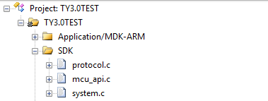
#### Verify the macro definition in protocol.h. <a href="#title-5-verify-20the-20macro-20definition-20in-20protocol.h." id="title-5-verify-20the-20macro-20definition-20in-20protocol.h."></a>

**Verify the product information**

(1) PRODUCT\_KEY is the product PID macro definition, the PID is the unique identifier of each product, which can be copied directly

![Overview of migrating Tuya's MCU SDK](https://airtake-public-data-1254153901.cos.ap-shanghai.myqcloud.com/goat/20200425/9d40dc58d99c4e6884a7f48a37a964b5.png)![Overview of migrating Tuya's MCU SDK](https://airtake-public-data-1254153901.cos.ap-shanghai.myqcloud.com/goat/20200425/34a36e7246ef4b5e91c137d785e4ec81.png)

Please ensure that the code is consistent with the product PID listed on the website, if not download the latest SDK development kit. The download location is as follows:![Overview of migrating Tuya's MCU SDK](https://airtake-public-data-1254153901.cos.ap-shanghai.myqcloud.com/goat/20200425/99b68f93d7884dddacd7273f2fe0a037.png)(2) MCU\_VER is the software version, the default is 1.0.0. If the MCU needs the OTA function, the new MCU code version number needs to be increased.![Overview of migrating Tuya's MCU SDK](https://airtake-public-data-1254153901.cos.ap-shanghai.myqcloud.com/goat/20200425/5c5263edd51e42daa93a900e420a0724.png)
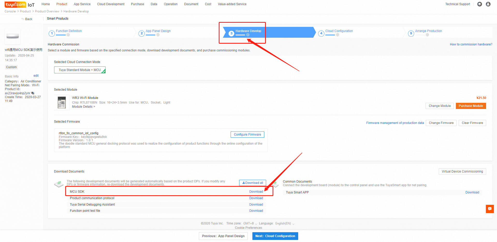
(3) CONFIG\_MODE is the network distribution mode, with default (AP and smart switch between each other) mode, security mode, and anti-mistouch mode. It is recommended to select the "anti-mistouch" mode.

Description of three distribution modes: ++Default mode++: AP and smart switch between each other. If the module is not configured or the configuration is removed, it will be in the state of network configuration after power-on and will remain. ++Safe Mode++: The module is in a non-distribution state after it is powered on from the factory. The MCU needs to send a reset command to enter the corresponding distribution mode. When the device is in the distribution state for a period of time (default 3 minutes), it is not When the user configures, the module will re-enter the non-distribution network state, and it needs to receive the reset command again to re-enter the network distribution mode. ++Anti-mistouch mode++: After the module is successfully configured by the user, after the local (MCU sends a reset command) reset, the device is in the state of network configuration, and it has not been reconfigured after a period of time (default 3 minutes). The module will automatically restore the user's network connection before resetting. After the local reset, the device is powered off abnormally, and the user's network connection before reset will be automatically restored after power on. In this mode, only when the device is removed from the APP by the user, the device will not record the last user's network connection and reconnect.

![Overview of migrating Tuya's MCU SDK](https://airtake-public-data-1254153901.cos.ap-shanghai.myqcloud.com/goat/20200425/6c5d7a5efe25405eabc6f5efef5e4c91.png)

When the security mode or anti-mistouch mode is selected, you can open the CONFIG\_MODE\_DELAY\_TIME macro definition and set the retention time of the distribution mode, the setting range is 3 \~ 10 minutes. If it is not turned on, the default value of 3 minutes will be set.

![Overview of migrating Tuya's MCU SDK](https://airtake-public-data-1254153901.cos.ap-shanghai.myqcloud.com/goat/20200425/9d8785f02f864a31b4d0719ece076603.png)

The smart mode and the smart mode AP of the distribution mode are switched by default, and only one mode can be used at the same time. If you want to use smart and AP coexistence mode, you can open the macro definition CONFIG\_MODE\_CHOOSE to set. When CONFIG\_MODE\_CHOOSE is set to 0, the network configuration mode is coexistence of smart and AP, and there is no need to switch the network configuration mode at this time. When CONFIG\_MODE\_CHOOSE is set to 1, the network configuration mode is only AP mode. Without opening the CONFIG\_MODE\_CHOOSE macro definition, the default configuration mode will be used.

![Overview of migrating Tuya's MCU SDK](https://airtake-public-data-1254153901.cos.ap-shanghai.myqcloud.com/goat/20200425/3f2b416ebb9d42eb8d60cdfca6fb82dd.png)

**Check whether the MCU firmware needs to be upgraded**

If OTA upgrade of MCU firmware is required, enable the firmware update macro, which is disabled by default.
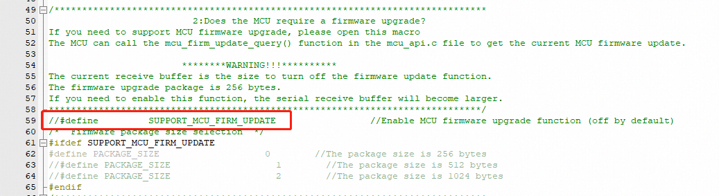
![Overview of migrating Tuya's MCU SDK](https://airtake-public-data-1254153901.cos.ap-shanghai.myqcloud.com/goat/20200425/546897f5d394499e8fe85954f3491000.png)

OTA upgrade needs to compile the bin file of the MCU code first (must be the bin file, also need to pay attention to increase the version number), and then configure the OTA upgrade on the platform, upload the bin file, then the APP will receive an upgrade reminder (silent upgrade will not Reminder) Click to agree to start the upgrade. After the upgrade is complete, restart the MCU. The module will query the MCU version number to verify whether the upgrade was successful. Several types of OTA (1) App reminder upgrade: In this upgrade mode, users will receive a pop-up window of the upgrade reminder every time they enter the device control panel. Whether to confirm the upgrade is confirmed by the user himself in the app (2) App silent upgrade: This upgrade method App will not have any reminder pop-up window, the firmware will automatically detect the upgrade within one minute after power on and find that there is a higher version of the upgrade package will automatically start to pull the relevant upgrade package After power-on, the module will go to the cloud every 24 hours to check whether there is an upgrade package configuration. (3) App mandatory upgrade: In this upgrade method, there will be an upgrade reminder pop-up window on the App side. If the user does not confirm the upgrade, the user cannot use the product's control panel normally. (4) App detection and upgrade: In this upgrade method, there will not be any pop-up window for upgrade reminder on the App side. Users must click on the relevant firmware version check on the App side. If there is a high-level firmware configuration, the upgrade prompt message will be displayed.

note: (1) OTA generally reads and writes flash. To ensure reliability, it is recommended to read the data just written after each write of flash data and verify the data to be written to ensure that the flash is written. Correctness. (2) It is recommended to add an OTA timeout detection to prevent the MCU from staying in the OTA data reception state when the OTA fails. (3) Each packet of OTA data has packet offset information. The packet offset can be used to detect whether the OTA data packet is heavy or missing.

**Define the transmitting and receiving buffers**

The size of the serial port receive buffer is affected by the frequency with which serial data processing is called. If the MCU processes the serial data faster, the serial port receive buffer size can be reduced appropriately; the serial port send buffer size should be greater than the longest DP data length of the data. The serial data processing buffer size should also be greater than the longest DP data length of the data, and the size should be adjusted according to whether the OTA function is required, whether weather services and the number of weather service types, and the number of days are required.
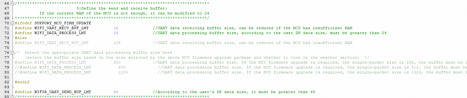
![Overview of migrating Tuya's MCU SDK](https://airtake-public-data-1254153901.cos.ap-shanghai.myqcloud.com/goat/20200425/ab1d3cf092ec4c45a398f1f039aa431a.png)

**(Mandatory) Define the working mode of the Wi-Fi module**

1\) If the distribution network trigger and indication are controlled by the MCU (the distribution button and LED are connected to the MCU end), select the "module and MCU co-processing" working mode (commonly used), please keep the WIFI\_CONTROL\_SELF\_MODE macro definition commented

![Overview of migrating Tuya's MCU SDK](https://airtake-public-data-1254153901.cos.ap-shanghai.myqcloud.com/goat/20200425/6f87b110109842dea3cc59bc008e3064.png)

2\) If the Wi-Fi indicator and buttons are connected to the Wi-Fi module (module self-processing working mode), please turn on the WIFI\_CONTROL\_SELF\_MODE macro definition, and then connect the indicator and the GPIO connected to the button according to the actual hardware Fill in the two lines below

**Check whether the Wi-Fi product testing function is enabled**

In order to ensure the final mass production efficiency and quality, it is recommended to open this macro.

![Overview of migrating Tuya's MCU SDK](https://airtake-public-data-1254153901.cos.ap-shanghai.myqcloud.com/goat/20200425/7e03233c64084cf58c57e25293278dd1.png)

Detailed production test process, you can view \[wifi general docking production test documentation]

**Weather service**

If you need the weather service function, you need to open the WEATHER\_ENABLE macro definition

![Overview of migrating Tuya's MCU SDK](https://airtake-public-data-1254153901.cos.ap-shanghai.myqcloud.com/goat/20200425/35b09dde9707442d84f441dbc77cf65e.png)

The weather service needs to be opened after the module is successfully connected to the route. After successful opening, the weather data will be delivered after the module is connected to the cloud, and thereafter, it will be delivered every 30 minutes. The weather service also needs to select the type of weather, you can select the options in the array weather\_choose in the protocol.c file,

![Overview of migrating Tuya's MCU SDK](https://airtake-public-data-1254153901.cos.ap-shanghai.myqcloud.com/goat/20200425/e9e4096c081047be87a6949703d84f5d.png)

After selection, write the number to WEATHER\_CHOOSE\_CNT macro definition.

![Overview of migrating Tuya's MCU SDK](https://airtake-public-data-1254153901.cos.ap-shanghai.myqcloud.com/goat/20200425/80c4e1a2bd7a4f6fb3e995b3c1979faa.png)

The module of the new firmware will support the weather forecast function for up to 7 days. The number of forecast days can be set in the WEATHER\_FORECAST\_DAYS\_NUM macro definition

![Overview of migrating Tuya's MCU SDK](https://airtake-public-data-1254153901.cos.ap-shanghai.myqcloud.com/goat/20200425/472da4d53a00421fbfc982e0346d9833.png)

When it is set to 1, it means that only the data of the day is obtained. When the setting value is 0 or> 7, the module will reply with an error message and the weather service fails to open. The weather data sent by the module will carry the information of the number of days, 0 means the day, and it needs attention here.

**Streaming service**

Streaming services are generally used for MCUs of the sweeper type, and are mainly used for the transmission of large amounts of data. If necessary, you can open WIFI\_STREAM\_ENABLE macro definition

![Overview of migrating Tuya's MCU SDK](https://airtake-public-data-1254153901.cos.ap-shanghai.myqcloud.com/goat/20200425/090f65e7f2aa4e7cb5faf98d8ac853d6.png)

**Other functions**

For other functions, if necessary, the user can open the corresponding macro definition and perfect related functions.

#### Migrating the protocol.c File and Invoking Functions <a href="#title-6-migrating-20the-20protocol.c-20file-20and-20invoking-20functions" id="title-6-migrating-20the-20protocol.c-20file-20and-20invoking-20functions"></a>

1. Use #include "wifi.h" in the files (for example, the main.c file) that require Wi-Fi–related files.
2. After MCU peripherals are initialized, invoke the wifi\_protocol\_init() function in the mcu\_api.c file.
3. Add the single-byte sending function of the MCU serial port to the uart\_transmit\_output function in the protocol.c file and delete #error. The following figure shows an example.

![Overview of migrating Tuya's MCU SDK](https://airtake-public-data-1254153901.cos.ap-shanghai.myqcloud.com/goat/20200425/d4e506be18d349dd8f42a80e6f362f0c.png)

1. Invoke the uart\_receive\_input function in the mcu\_api.c file in the serial port receiving interrupt service function, and use the received characters as parameter input. The following figure shows an example.
![Overview of migrating Tuya's MCU SDK](https://airtake-public-data-1254153901.cos.ap-shanghai.myqcloud.com/goat/20200425/229399e4f9ee4ee386e2e2d79c26f38c.png)

1. Invoke the wifi\_uart\_service() function in the mcu\_api.c file after the MCU enters the while cycle. The following shows an example of code structure in main.c.

```
include "wifi.h"
...
void main(void)
{
    wifi_protocol_init();
    ...
    while(1)
    {
        wifi_uart_service();
        ...
    }
}
```

Note: The MCU must directly invoke the wifi\_uart\_service() function in the mcu\_api.c file in while. After the program is successfully initialized, it is recommended that the serial port interrupt not be disabled. If the serial port interrupt must be disabled, ensure that the interrupt is disabled for only a short time to prevent serial port data loss. Do not invoke the report function in the interrupt.

#### Processing DP Data Report and Delivery Functions <a href="#title-7-processing-20dp-20data-20report-20and-20delivery-20functions" id="title-7-processing-20dp-20data-20report-20and-20delivery-20functions"></a>

There are 6 main types of dp (1) bool type: The bool type is generally the dp of some switches, such as switch, ECO, and screen display. (2) Enum type: The enum type is generally used as dp with various states, such as working mode, wind speed, wind swing position. (3) Value type: The value type is generally used as the value type dp, such as the set temperature value, current temperature value, and power. (4) Fault type: The fault type is generally used for fault reporting, and the data is usually performed in bitmap format. (5) String type: String is generally used as a string type dp, some dp need to be transmitted in the form of a string, you can use this type. There are some dp that are inconvenient to use bool, enum, value, fault type, this type can also be used. (6) Raw type: The raw type is generally used for data that needs to be transparently transmitted. There is no requirement for the data format. Plain text or encryption can be used. When using it, the sender and receiver must communicate the data format, package and parsing method.

**Reporting data of all DPs**

After the Wi-Fi module restarts or the network is reconfigured, the Wi-Fi module proactively delivers a status query command. The MCU needs to report the status of the device's DPs to the Wi-Fi module for synchronization. (1) Open protocol.c and locate the all\_data\_update(void) function. (2) Enter initial values of all DPs to be reported into corresponding report functions. The values will be displayed on the App control panel. Note: Do not invoke the all\_data\_update() function manually. This function is automatically invoked at a specific time.

![Overview of migrating Tuya's MCU SDK](https://airtake-public-data-1254153901.cos.ap-shanghai.myqcloud.com/goat/20200425/1b83048525cd4337a45665b92a8b3915.png)

**Reporting data of a single DP**

When the status of a DP is changed, the MCU proactively reports the new DP status to the Wi-Fi module, and the DP status displayed on the App will be updated accordingly. The report data format is mcu\_dp\_xxxx\_updata(DPID\_X,n). DPID\_X indicates the DP whose status has changed. Functions in all\_data\_update() can be independently invoked. Example:

```
mcu_dp_bool_update(DPID_SWITCH,1); //Boolean data reporting
mcu_dp_value_update(DPID_TEMPER_SET,25); //Value data reporting
mcu_dp_string_update(DPID_DAY,"1234",4); //String data reporting
```

**DP data delivery**

Each deliverable DP has an independent data delivery processing function in the protocol.c file. The function format is dp\_download\_xxx\_handle(), and xxx indicates a deliverable DP. After the function parses a DP, the MCU performs logical control in the corresponding position. The following shows an example of receiving switch data.![Overview of migrating Tuya's MCU SDK](https://images.tuyacn.com/smart/announcement/A_SDK14.png)The MCU uses MCU\_ON\_switch1() and MCU\_OFF\_switch1() to turn on and off a switch, respectively. When the device status is changed under non-App control, the MCU invokes mcu\_dp\_bool\_update(DPID\_SWITCH\_1,switch\_1) to upload the real status of the switch. Typically, the receiving processing function automatically invokes the function.

#### Optimize the network configuration and indicator functions. <a href="#title-8-optimize-20the-20network-20configuration-20and-20indicator-20functions." id="title-8-optimize-20the-20network-20configuration-20and-20indicator-20functions."></a>

Skip this section if processing by the Wi-Fi module is used. When protocol migration is successful, the network configuration command and indicator function need to be optimized for network configuration. In mode of cooperative processing by the Wi-Fi module and MCU, the MCU can select the network configuration triggering and indication modes based on actual requirements. Typically, network configuration is triggered by the Wi-Fi reset button and indicated by quick or slow blinking of the Wi-Fi indicator. We recommend that you enable both network configuration modes for your product. Smart network configuration mode: The operation is simple and convenient, and the Wi-Fi indicator blinks quickly. AP network configuration mode: Network configuration is reliable, and the Wi-Fi indicator blinks slowly.

**Network configuration command**

The network configuration command can be implemented by the mcu\_reset\_wifi() and mcu\_set\_wifi\_mode() functions. Typically, these two functions are invoked in the button processing function after the button is pressed for network configuration. After mcu\_reset\_wifi() is invoked, the Wi-Fi module is reset and the previous network configuration information is cleared. The function invoking also triggers a switchover between the AP and smart network configuration modes.![Overview of migrating Tuya's MCU SDK](https://images.tuyacn.com/smart/aircondition/mcu-dev7.png)

After mcu\_set\_wifi\_mode() with parameter SMART\_CONFIG or AP\_CONFIG is invoked, the network configuration information is cleared, and smart or AP network configuration mode is used. This function has the same function as the mcu\_reset\_wifi() function. You can select one as needed.

**Network configuration indication**

Typically, the mcu\_get\_wifi\_work\_state() function is invoked at while(1) to return the Wi-Fi status. Then, you write the indicator blinking mode in based on the Wi-Fi status.

| Device Network Connection Status | Description                                                                  | Status Value | LED Indicator Status                       |
| -------------------------------- | ---------------------------------------------------------------------------- | ------------ | ------------------------------------------ |
| State 1                          | Smart network configuration                                                  | 0x00         | The indicator blinks at 250 ms intervals.  |
| State 2                          | AP network configuration                                                     | 0x01         | The indicator blinks at 1500 ms intervals. |
| State 3                          | The Wi-Fi is configured. However, the device fails to connect to the router. | 0x02         | The indicator is off.                      |
| State 4                          | The Wi-Fi is configured, and the device successfully connects to the router. | 0x03         | The indicator is steady on.                |
| State 5                          | The device connects to the router and cloud.                                 | 0x04         | The indicator is steady on.                |
| State 6                          | The Wi-Fi device is in low power consumption mode.                           | 0x05         | The indicator is off.                      |
| State 7                          | The Wi-Fi device is insmartconfig\&AP consumption mode.                      | 0x06         | TThe indicator blinks at 250 ms intervals. |

Invoke the mcu\_get\_wifi\_work\_state() function to obtain the Wi-Fi status. The function architecture is as follows:

```
    void main(void)
    {
    	...

    	while(1)
    	{
    		switch(mcu_get_wifi_work_state())
    		{
    			case SMART_CONFIG_STATE:
    			//smart config configuration state: LED flash quickly; the user needs to complete the configuration
    			break;
    			case AP_STATE:
    			//AP configuration state: LED flash slowly
    			break;
    			case WIFI_NOT_CONNECTED:
    			//Wi-Fi configuration is finished; the router is being connected to; LED keeps long dark
    			break;
    			case WIFI_CONNECTED:
    			//The router is successfully connected to; LED keeps long bright
    			break;
    			default:break;
    		}
    		...
    	}
    }
```

Description of network status:

| Device Network Connection Status | Description                                                                  | Description                                                                                                                                                                                                         |
| -------------------------------- | ---------------------------------------------------------------------------- | ------------------------------------------------------------------------------------------------------------------------------------------------------------------------------------------------------------------- |
| State 1                          | Smart network configuration                                                  | The wifi module is in smart distribution state                                                                                                                                                                      |
| State 2                          | AP network configuration                                                     | wifi module is in AP configuration                                                                                                                                                                                  |
| State 3                          | The Wi-Fi is configured. However, the device fails to connect to the router. | The wifi module has received configuration information and is connecting to the router                                                                                                                              |
| State 4                          | The Wi-Fi is configured, and the device successfully connects to the router. | The wifi module is connected to the router, but is not connected to the cloud. If the module has been equipped with a network and the mobile phone is also connected to this route, it can be controlled by the LAN |
| State 5                          | The device connects to the router and cloud.                                 | The wifi module has been connected to the cloud, and both the LAN and the external network can be controlled at this time                                                                                           |
| State 6                          | The Wi-Fi device is in low power consumption mode.                           | wifi module enters low power consumption state                                                                                                                                                                      |
| State 7                          | The Wi-Fi device is insmartconfig\&AP consumption mode.                      | The wifi module is in smart & AP state, at this time, it can be either smart or AP.                                                                                                                                 |

#### Perfect production test function <a href="#title-9-perfect-20production-20test-20function" id="title-9-perfect-20production-20test-20function"></a>

The production test has the following three forms, you can choose according to your product docking situation \* Common platform Wi-Fi function test process-scan specified route \* Common platform Wi-Fi function test process-connect designated route \* Common platform Wi-Fi function test process-infrared function test

The specific process can be viewed: \[Wi-Fi General Production Test Documentation]

### MCU\_SDK and module data communication guide <a href="#title-10-mcu_sdk-20and-20module-20data-20communication-20guide" id="title-10-mcu_sdk-20and-20module-20data-20communication-20guide"></a>

The frame format can refer to the protocol description document in the SDK development kit

#### Initialize communication <a href="#title-11-initialize-20communication" id="title-11-initialize-20communication"></a>

After the MCU and the module are powered on, some initial configuration is required. During this period, it is necessary to verify whether the MCU and the module can work normally, whether the communication connection is normal, the data required for the module activation, and the module acquisition work method.

**Heartbeat packet**

The heartbeat packet is the data for regular communication between the MCU and the module. It can be used as a basis for verifying whether the MCU or the module is working properly. Therefore, it is recommended that the frame for the first communication after the MCU and the module are powered on is the heartbeat packet. Only when the heartbeat packet is sent and the reply is normal, can the communication be continued.

**Query product information**

After the heartbeat package can interact normally, the module needs to query the product PID, version number, and network configuration method of the MCU firmware. The PID is used for product activation. The version number is used to verify whether the upgrade is successful after the OTA upgrade is completed. The distribution network mode of the module.

**Query MCU, set the working mode of the module**

Used to set the working mode of the module, select the MCU and module co-processing mode or module self-processing mode It can be selected according to the WIFI network status indicator and the hardware connection position of the module reset button.

#### Data interaction process <a href="#title-12-data-20interaction-20process" id="title-12-data-20interaction-20process"></a>
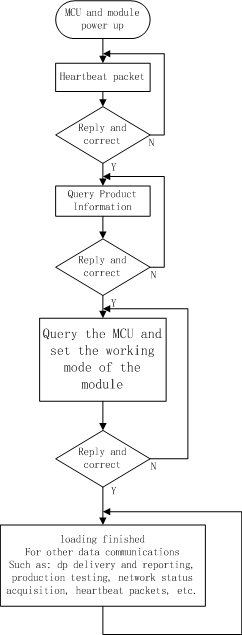
![Overview of migrating Tuya's MCU SDK](https://airtake-public-data-1254153901.cos.ap-shanghai.myqcloud.com/goat/20200425/fe7fd2a7832148d090f01e9d986738f1.png)

#### Data interaction considerations <a href="#title-13-data-20interaction-20considerations" id="title-13-data-20interaction-20considerations"></a>

Special Note: 1. In order to avoid unpredictable problems, it is recommended that normal data communication such as dp delivery and reporting, OTA upgrade, etc. should be performed after initialization is completed. 2. For devices with low power consumption and other MCUs that can control the power of the module, data interaction must be performed after the device is initialized.


# Wi-Fi Power Off Fast Connect Device Solution


# Overview

### Introduction <a href="#title-0-introduction" id="title-0-introduction"></a>

There are many security sensors in the market. Their product features are generally battery-powered, low power consumption, small size, and weak interaction. Wi-Fi low-power solutions are specifically designed for this category. The communication schematic diagram is as follows. Users only need to use the Tuya Wi-Fi low-power docking protocol to quickly complete the docking of the MCU, so that the device can be networked. Tuya provides complete modules, App, and cloud services during the process.

Compared with the Wi-F universal module solution, the Wi-Fi low-power module software is trimmed and optimized. In addition, after the data transmission is completed, the MCU needs to power off the module.

![Wi-Fi Power Off Fast Connect Device  Development Overview](https://airtake-public-data.oss-cn-hangzhou.aliyuncs.com/goat/20200311/9d65c82b99d848ac953dd0e7df7869bd.jpg)

* One minute network configuration (time is optional) The default is 3 minutes.

### Development Process

The development process mainly includes: product creation-hardware debugging-software development-functional debugging.

#### Create Product

Log in to the [IoT Workbench](https://iot.tuya.com/) and create a product. Select the product category according to the actual needs, and select Wi-Fi for the networking method. After the product is created, you can select the functions, panels, modules, and firmware according to the actual needs of the product and then download it to the MCU development kit.

> Some product categories have extended options for power consumption. For normal power supply products, we can choose standard power consumption. Battery-powered products can choose low power consumption.
>
> **Note:** Power consumption selection will be related to the recommendation of subsequent modules and firmware.

Creating a product is described in detail in the [MCU Access Guide](https://docs.tuya.com/en/iot/device-development/access-mode-mcu/mcu-access-guide/mcu-access-guide), so I won't repeat it here. For specific steps, please refer to: [Product Creation-IoT Platform Operation](https://docs.tuya.com/en/iot/device-development/access-mode-mcu/mcu-access-guide/mcu-access-guide#IoT%20Platform%20Operation)

![Wi-Fi Power Off Fast Connect Device  Development Overview](https://airtake-public-data.oss-cn-hangzhou.aliyuncs.com/goat/20200316/3ff8f7c2125546aa88e365354e095151.png)

#### Hardware debugging <a href="#title-3-hardware-20debugging" id="title-3-hardware-20debugging"></a>

**Hardware selection**

When creating a product selection module, the platform will recommend some common module models. The recommended module models for low-power Wi-Fi communication solutions are as follows:

* **E2S / E3S** Firmware key: keyvw8xqm89v5vr4
* **XR1 / XR2 / XR3** Firmware key: keycnw55p5k7vueh

![Wi-Fi Power Off Fast Connect Device  Development Overview](https://airtake-public-data.oss-cn-hangzhou.aliyuncs.com/goat/20200316/dd240c9e121c462d81acc435bb1195f5.png)

After selecting the module and firmware, you can purchase module samples online.

The hardware engineer can enter the drawing board stage, and the related materials for hardware development can be viewed in the document center:

Data manual link: [Wi-Fi module data manual](https://docs.tuya.com/en/iot/device-development/module/wifi-module/wifie1smodule)

Module minimum schematic: [Wi-Fi module minimal system schematic diagram](https://docs.tuya.com/en/iot/device-development/access-mode-mcu/hardware-design-reference-wifi/wifie1smodulemcu) PCB data: [Common module package library](https://pan.baidu.com/s/10xJBTxyDQjweUI6C6LhrNQ)

**Note:** Wi-Fi low-power modules consume less power than Wi-Fi universal modules, but the peak current will reach more than 400mA (continuing us level), and there must be a margin when designing the power supply!

**Distribution Network Verification**

After getting the module, users do n’t need to worry about writing code first. It is recommended to use the module debugging assistant (MCU simulation mode) provided by Tuya to connect with the Wi-Fi module first. When verifying the module, users can be familiar with The protocol interaction process will greatly improve the efficiency of development and debugging later.

![Wi-Fi Power Off Fast Connect Device  Development Overview](https://airtake-public-data.oss-cn-hangzhou.aliyuncs.com/goat/20200316/9f6305b249414495b85e3b6fd90a9b06.png)

![Wi-Fi Power Off Fast Connect Device  Development Overview](https://airtake-public-data.oss-cn-hangzhou.aliyuncs.com/goat/20200313/3229f260ab804d45ac7c6ec8c50b39b2.png)

Tuya module debugging assistant-MCU simulation mode. The assistant will simulate the MCU to automatically reply the module's correct protocol data. After the module is networked with a mobile phone, the DP data can be reported and issued. The following briefly introduces the main steps of the assistant and module distribution network operation. Before using it, you need to know the instructions of Tuya Module Debugging Assistant in advance. Users who use the assistant for the first time can read in advance: [Module Debugging Assistant Instruction](https://docs.tuya.com/en/iot/device-development/access-mode-simmulator/access-mode-mdodule-simmulator)

**step1.** According to the minimum system schematic diagram, set up the module peripheral circuit, and simple test can directly fly the wire.

**step2.** Open the Tuya module debugging assistant in the development kit and import the debugging file. Protocol selection Wi-Fi Low power protocol, MCU simulation mode.

**step3.** Connect the serial port of the module to the computer through the USB to TTL tool. The assistant selects the corresponding serial port and baud rate. Open the serial port and click Start. You will see that the module and the host computer automatically perform the initialization process protocol interaction.

**Note:** Wi-Fi low-power module sends **01** command word upon power-on. After receiving the correct response, it will interact with subsequent initialization protocols. If no data is sent after power-on, please check whether the peripheral circuit of the module is correct.

**step4.** Click Reset Module, the module enters the network distribution mode. The module supports two modes of network configuration: EZ and AP mode ([the difference between EZ mode and AP mode](https://support.tuya.com/en/help/_detail/K9d1qfql1dekm)). The reset button will switch the network configuration mode. According to the status prompt, the App performs the corresponding network configuration operation. For the network configuration operation, you can read the instruction of the App. Attach a demo video of the network distribution in two modes:

![Wi-Fi Power Off Fast Connect Device  Development Overview](https://airtake-public-data.oss-cn-hangzhou.aliyuncs.com/goat/20200316/60759b9dbb934e0297613c6a50cd6067.png)

#### Software Development <a href="#title-4-software-20development" id="title-4-software-20development"></a>

In the process of hardware debugging, the user saw that the module and the MCU have a series of serial protocol protocol interaction data. For the understanding of these data, please refer to the protocol document in the development kit.

The agreement is mainly divided into two parts: the basic agreement and the functional agreement. The basic protocol has nothing to do with the product. It is a common protocol of the module, including module initialization instructions and some extended function instructions. The function protocol part is mainly based on the command word of the report of the basic protocol, and has explained the DP data content format in detail. The complete content of the basic protocol, the document center is kept updated in real time, you can click the link to view: [Tuya-cloud-low-power-universal-serial-access-protocol](https://docs.tuya.com/zh/iot/device-development/access-mode-mcu/wifi-low-power-solution/tuyacloudlowpoweruniversalserialaccessprotocol)

There are two ways for MCU to interface with Tuya module: transplant the MCU SDK or connect the protocol by yourself.

* Self-docking agreement

  When MCU resources are limited or the MCU SDK is not suitable for porting, customers can choose to connect the serial port protocol by themselves.
* Porting MCU SDK

  If the MCU resources are sufficient, it is generally recommended that users directly port the MCU SDK for efficient and convenient development. The MCU SDK in the development kit is a C-based protocol application code provided by Tuya, which can be directly added to the MCU project. The MCU SDK requires MCU hardware resources: 4K bytes of Flash; RAM is related to the length of the DP point data, about 100 bytes (if OTA function is required, it must be greater than 260 bytes); the number of function nesting levels is 9 levels. If users with insufficient resources can connect the protocol by themselves, the functions in the SDK package can still be used as a reference.

  MCU SDK Porting Tutorial: [Overview of migrating Tuya's MCU SDK](https://docs.tuya.com/en/iot/device-development/access-mode-mcu/software-reference-wifi/overview-of-migrating-tuyas-mcu-sdk)

**Power off mechanism**

When distributing the network: Compared with the general solution, the low power consumption, if the module is not connected to the cloud within 3 minutes of the distribution network, the module will automatically enter the power consumption mode. The module will actively issue 55 aa 00 03 00 01 01

#### Functional debugging <a href="#title-5-functional-20debugging" id="title-5-functional-20debugging"></a>

After porting the MCU SDK code development, you can use the Tuya module debugging assistant-module simulation mode to verify the correctness of the MCU code. The usage method is similar to the MCU simulation mode. In the simulation module mode, the assistant will automatically send the initialization data stream to verify that the MCU response is correct and give corresponding prompts for the incorrect data. After the initial interaction is passed, you can manually click to test other extended functions.

**Note:** Tuya module debugging assistant module simulation mode, without networking function, only used to verify the correctness of MCU serial protocol transmission and reception. After the test is completed, the MCU can be connected to the actual module and network.

![Wi-Fi Power Off Fast Connect Device  Development Overview](https://airtake-public-data.oss-cn-hangzhou.aliyuncs.com/goat/20200316/45fa0a5700a042d0ba2018fda4bf5617.png)

![Wi-Fi Power Off Fast Connect Device  Development Overview](https://airtake-public-data.oss-cn-hangzhou.aliyuncs.com/goat/20200316/4def53dbe18a412788315ac75bb3e236.png)

Debugging common tool links:

[Background log query entry](https://docs.tuya.com/en/iot/guidelines-for-platform/operation-center/operation#Log%20query%3A%20Use%20Behavior%20Query%20on%20a%20Single-Device%20Basis): IoT Workbench-Operation Center. You can query related device background log data based on the device ID.

[Tuya Online Support Portal](https://docs.tuya.com/en/iot/guidelines-for-platform/support-center/troubleshooting): Tuya provides online support services. If the problem documents cannot be answered, you can Ask questions directly online, and the professional and technical team will answer your questions.

[FAQ collection for open platform](https://docs.tuya.com/en/iot/device-development/access-mode-mcu/faqs-wifi/tuya-question): develop common problems, understand them in advance, and avoid stepping into the pit.


# Zigbee General Solution


# Overview

## Introduction <a href="#title-0-introduction" id="title-0-introduction"></a>

The Zigbee universal solution is one of the mainstream MCU interconnection solutions. MCU only need to use the Tuya Zigbee universal serial port access protocol to quickly complete the MCU docking, so that the device can be connected to the Internet. Tuya provides complete modules, App, and cloud services during the process.

Compared with other communication module solutions, Zigbee modules require a gateway, have a short distance but low power consumption.

This article is mainly an overview of the development process of Tuya Zigbee universal solution MCU.

## Development Process <a href="#title-1-development-20process" id="title-1-development-20process"></a>

The development process mainly includes: product creation-hardware debugging-software development-functional debugging.

### Create Product <a href="#title-2-create-20product" id="title-2-create-20product"></a>

Log in to the [IoT Workbench](https://iot.tuya.com/) and create a product. Select the product category according to the actual needs, and select Zigbee for the networking method. After the product is created, you can select the functions, panels, modules, and firmware according to the actual needs of the product and then download it to the MCU development kit.

Creating a product is described in detail in the [MCU Access Guide](https://docs.tuya.com/en/iot/device-development/access-mode-mcu/mcu-access-guide/mcu-access-guide), so I won't repeat it here. For specific steps, please refer to: [Product Creation-IoT Platform Operation](https://docs.tuya.com/en/iot/device-development/access-mode-mcu/mcu-access-guide/mcu-access-guide#IoT%20Platform%20Operation)

![](https://2999784448-files.gitbook.io/~/files/v0/b/gitbook-legacy-files/o/assets%2F-MBlD-pGvqUEQDs9SdgH%2F-MBnzq8q6FFO9MOOTTBV%2F-MBnzsgu-_8n7GEm47qO%2Fimage.png?alt=media\&token=f4d441b9-fc4c-4d00-81b0-7c3761d57fbf)

### Hardware debugging <a href="#title-3-hardware-20debugging" id="title-3-hardware-20debugging"></a>

#### Hardware selection <a href="#subtitle-4-hardware-20selection" id="subtitle-4-hardware-20selection"></a>

When creating a product selection module, the platform will recommend some common module models. The most commonly used Zigbee modules in the Zigbee universal solution are TYZS3 and TYZS5.

![](https://2999784448-files.gitbook.io/~/files/v0/b/gitbook-legacy-files/o/assets%2F-MBlD-pGvqUEQDs9SdgH%2F-MBnzq8q6FFO9MOOTTBV%2F-MBnzy8RPSqdlJURWNTe%2Fimage.png?alt=media\&token=3c53a0af-b5d0-466a-b508-0367e672f38b)

Tuya Zigbee module, divided into strong current and weak current firmware. Strong current firmware is suitable for products with long power supply and insensitive to power consumption. Weak current firmware is suitable for battery-powered products that require higher power consumption.

After selecting the module and firmware, you can purchase module samples online.

The hardware engineer can enter the drawing board stage, and the related materials for hardware development can be viewed in the document center:

Data manual link: [Zigbee module data manual](https://docs.tuya.com/en/iot/device-development/module/zigbee-module/tyzs5-zigbee-module-datasheet)

Module minimum schematic: [Zigbee module minimal system schematic diagram](https://docs.tuya.com/en/iot/device-development/access-mode-mcu/zigbee-general-solution/zigbee-module-mcu-development-overview/zigbee-module-mcu-development-overview?id=K9eibbird3q5x)

PCB data: [Common module package library](https://pan.baidu.com/s/10xJBTxyDQjweUI6C6LhrNQ)

#### Distribution Network Verification <a href="#subtitle-5-distribution-20network-20verification" id="subtitle-5-distribution-20network-20verification"></a>

After getting the module, users do n’t need to worry about writing code first. It is recommended to use the module debugging assistant (MCU simulation mode) provided by Tuya to connect with the Zigbee module first. When verifying the module, users can be familiar with The protocol interaction process will greatly improve the efficiency of development and debugging later.

![](https://2999784448-files.gitbook.io/~/files/v0/b/gitbook-legacy-files/o/assets%2F-MBlD-pGvqUEQDs9SdgH%2F-MBnzq8q6FFO9MOOTTBV%2F-MBo-4lSQE4x6CmPJy4L%2Fimage.png?alt=media\&token=c62c6640-910d-4937-84be-c3f2e8cbe1bd)

Tuya module debugging assistant-MCU simulation mode. The assistant will simulate the MCU to automatically reply the module's correct protocol data. After the module is networked with a mobile phone, the DP data can be reported and issued. The following briefly introduces the main steps of the assistant and module distribution network operation. Before using it, you need to know the instructions of Tuya Module Debugging Assistant in advance. Users who use the assistant for the first time can read in advance: [Module Debugging Assistant Instruction](https://docs.tuya.com/en/iot/device-development/access-mode-simmulator/access-mode-mdodule-simmulator)

**step1.** According to the minimum system schematic diagram, set up the module peripheral circuit, and simple test can directly fly the wire.

**step2.** Open the Tuya module debugging assistant in the development kit and import the debugging file. Protocol selection Wi-Fi universal protocol, MCU simulation mode.

**step3.** Connect the serial port of the module to the computer through the USB to TTL tool. The assistant selects the corresponding serial port and baud rate. Open the serial port and click Start. You will see that the module and the host computer automatically perform the initialization process protocol interaction.

**Note:** If no data is sent after power on, please check if the peripheral circuit of the module is correct.

**step4.** Click Reset Module, the module enters the network distribution mode. According to the status prompt, the App performs the corresponding network configuration operation. For the network configuration operation, you can read the instruction of the App.

**Note:** Before configuring the sub-device, the gateway needs to be connected to the Internet with Tuya Smart or Smart Life App before adding the Zigbee sub-device. For details, please refer to the document [Zigbee Network Configuration Instructions](http://faq.cn.tuya.com/helpDetail.htm?tntInstId=WRNQWLCN\&helpCode=SCE_00000130\&helpId=90972006) and video [Zigbee Gateway Network Configuration](https://www.bilibili.com/video/av94188714?from=search\&seid=3135414516402258372)

![](https://2999784448-files.gitbook.io/~/files/v0/b/gitbook-legacy-files/o/assets%2F-MBlD-pGvqUEQDs9SdgH%2F-MBnzq8q6FFO9MOOTTBV%2F-MBo-BR5oMO5uzANeSa-%2Fimage.png?alt=media\&token=66d7da00-6de1-4e66-94ba-7fbbeb8e4307)

### Software Development <a href="#title-4-software-20development" id="title-4-software-20development"></a>

In the process of hardware debugging, the user saw that the module and the MCU have a series of serial protocol protocol interaction data. For the understanding of these data, please refer to the protocol document in the development kit.

The agreement is mainly divided into two parts: the basic agreement and the functional agreement. The basic protocol has nothing to do with the product. It is a common protocol of the module, including module initialization instructions and some extended function instructions. The function protocol part is mainly based on the command word of the report of the basic protocol, and has explained the DP data content format in detail. The complete content of the basic protocol, the document center is kept updated in real time, you can click the link to view: [Tuya Zigbee module UART communication protocol](https://docs.tuya.com/en/iot/device-development/access-mode-mcu/zigbee-general-solution/tuya-zigbee-module-uart-communication-protocol/tuya-zigbee-module-uart-communication-protocol)

There are two ways for MCU to interface with Tuya module: transplant the MCU SDK or connect the protocol by yourself.

* Self-docking agreement

  When MCU resources are limited or the MCU SDK is not suitable for porting, customers can choose to connect the serial port protocol by themselves.
* Porting MCU SDK

  If the MCU resources are sufficient, it is generally recommended that users directly port the MCU SDK for efficient and convenient development. The MCU SDK in the development kit is a C-based protocol application code provided by Tuya, which can be directly added to the MCU project. The MCU SDK requires MCU hardware resources: 4K bytes of Flash; RAM is related to the length of the DP point data, about 100 bytes (if OTA function is required, it must be greater than 260 bytes); the number of function nesting levels is 9 levels. If users with insufficient resources can connect the protocol by themselves, the functions in the SDK package can still be used as a reference.

  MCU SDK Porting Tutorial: [Overview of migrating Tuya's MCU SDK](https://docs.tuya.com/en/iot/device-development/access-mode-mcu/software-reference-wifi/overview-of-migrating-tuyas-mcu-sdk)

### Functional debugging <a href="#title-5-functional-20debugging" id="title-5-functional-20debugging"></a>

After porting the MCU SDK code development, you can use the Tuya module debugging assistant-module simulation mode to verify the correctness of the MCU code. The usage method is similar to the MCU simulation mode. In the simulation module mode, the assistant will automatically send the initialization data stream to verify that the MCU response is correct and give corresponding prompts for the incorrect data. After the initial interaction is passed, you can manually click to test other extended functions.

**Note:** Tuya module debugging assistant module simulation mode, without networking function, only used to verify the correctness of MCU serial protocol transmission and reception. After the test is completed, the MCU can be connected to the actual module and network.

![](https://2999784448-files.gitbook.io/~/files/v0/b/gitbook-legacy-files/o/assets%2F-MBlD-pGvqUEQDs9SdgH%2F-MBnzq8q6FFO9MOOTTBV%2F-MBo-ICfCfIWLDvMg5r9%2Fimage.png?alt=media\&token=426584a4-5b06-4c50-9887-91eddbedeae2)

![](https://2999784448-files.gitbook.io/~/files/v0/b/gitbook-legacy-files/o/assets%2F-MBlD-pGvqUEQDs9SdgH%2F-MBnzq8q6FFO9MOOTTBV%2F-MBo-Ksqbxyqe-rYkicu%2Fimage.png?alt=media\&token=e156d17a-f1d4-481f-82cb-3704e6d79071)

Debugging common tool links:

[Background log query entry](https://docs.tuya.com/en/iot/guidelines-for-platform/operation-center/operation#Log%20query%3A%20Use%20Behavior%20Query%20on%20a%20Single-Device%20Basis): IoT Workbench-Operation Center. You can query related device background log data based on the device ID.

[Tuya Online Support Portal](https://docs.tuya.com/en/iot/guidelines-for-platform/support-center/troubleshooting): Tuya provides online support services. If the problem documents cannot be answered, you can Ask questions directly online, and the professional and technical team will answer your questions.


# Software development


# Tuya Zigbee module UART communication protocol

The Tuya Zigbee serial port general protocol is the Tuya custom Zigbee module serial port general protocol, which is mainly used for Tuya Zigbee module to directly connect with other MCU serial ports for serial communication.

Figure 1: Tuya Zigbee serial protocol structure

### Hardware connection <a href="#title-0-hardware-20connection" id="title-0-hardware-20connection"></a>

Zigbee module is powered by DC 3.3V, UART is set to 9600-8-N-1, no data flow control. The UART interface pins use standard logic. In the idle state, the TXD and RXD pins are both high level, with low level as the start bit and high level as the stop bit. The pin stays high even when the device goes to sleep.

For low-power devices, two GPIO ports (PWM1 and PWM2) are reserved between the Tuya Zigbee module and the MCU, which are used when the MCU and module connection wake up. PWM1 is used by the Zigbee module to wake the MCU, and PWM2 is used by the MCU to wake the Zigbee module. The default is high level, low level is valid for more than 10 ms. For low-power low-voltage devices, the initiator needs to make a wake-up handshake connection before actively initiating a command between the Zigbee module and the MCU.

For high-power devices without hibernation, the serial port is in a long listening state and does not need to be connected to PWM1 and PWM2. It can be left floating.

## Serial communication

### Frame format <a href="#title-1-frame-20format" id="title-1-frame-20format"></a>

The UART communication data frame between Tuya Zigbee module and MCU is composed of frame header (Front), version (Ver), command word (Cmd), data length (Length), data (Data) and checksum (Check). And description is as follows:

| Octets: 2 | 1   | 2   | 1   | 2      | Variable | 1     |
| --------- | --- | --- | --- | ------ | -------- | ----- |
| Front     | Ver | Seq | Cmd | Length | Data     | Check |

### Frame Format Description <a href="#title-2-frame-20format-20description" id="title-2-frame-20format-20description"></a>

| Field                 | Description                                                                                                  |
| --------------------- | ------------------------------------------------------------------------------------------------------------ |
| Frame Header (Front)  | 2 byte leader, fixed to 0x55aa                                                                               |
| Version (Ver)         | Serial communication protocol version, for upgrading and expansion                                           |
| Sequence number (seq) | The sequence number of the transmitted data, ranging from 0 to 65535, and returned to 0 after reaching 65535 |
| Command Word (Cmd)    | For specific frame types, refer to \[Table 2] (# 表 1)                                                        |
| Data length (Length)  | effective data length of the transmission; single frame data length does not exceed 64 bytes                 |
| Data                  | Valid Data Transferred                                                                                       |
| Check                 | Check the data, starting from the header of the frame and summing the results by 256 bytes                   |

Table 1: Frame format description

Note: The version (Ver) is 1, and does not include the serial number parameter; The version number is greater than 1, including the serial number parameter;

| Cmd ID    | Description                                                 |
| --------- | ----------------------------------------------------------- |
| 0x01      | Product Information Inquiry / Reporting                     |
| 0x02      | Device Status Query / Report                                |
| 0x03      | Zigbee Device Reset                                         |
| 0x04      | Order Issuance                                              |
| 0x05      | Status Report                                               |
| 0x06      | Status Search                                               |
| 0x07      | reserved                                                    |
| 0x08      | Zigbee Device Functional Test                               |
| 0x09      | Query key information (only scene switch devices are valid) |
| 0x0A      | Scene wakeup command (only scene switch device is valid)    |
| 0x0A-0x23 | reserved                                                    |
| 0x24      | Time synchronization                                        |

Table 2: Cmd description table

All data larger than 1 byte is transferred in big-endian mode.

Under normal circumstances, the command word one send and one receive synchronization mechanism is adopted, that is, one party sends a command and the other responds. If the sender does not receive the correct response packet after timeout, the transmission timeout.

## Protocol details

### Query Product Information <a href="#title-3-query-20product-20information" id="title-3-query-20product-20information"></a>

Explanation:

1\) Product ID: Corresponds to the Tuya Developer Platform PID (Product Identification), which is generated by the Tuya Cloud Developer Platform and used to record product-related information in the cloud.

2\) Product information consists of product ID and MCU software version.

3\) MCU software version number format definition: in dotted decimal form, "x.x.x" (0 <= x <= 99), x is a decimal number.

Module sends:

| Field         | Length (byte) | Description                                                  |
| ------------- | ------------- | ------------------------------------------------------------ |
| Frame Header  | 2             | 0x55aa                                                       |
| Version       | 1             | 0x02                                                         |
| Serial number | 2             | N                                                            |
| Command Word  | 1             | 0x01                                                         |
| Data length   | 2             | 0x0000                                                       |
| Data          | 0             | None                                                         |
| Checksum      | 1             | Byte-sum results from the header of the frame, 256 remainder |

Example: 0x55aa 02 N 01 0000 xx

The MCU returns:

| Field         | Length (byte) | Description                                                  |
| ------------- | ------------- | ------------------------------------------------------------ |
| Frame Header  | 2             | 0x55aa                                                       |
| Version       | 1             | 0x02                                                         |
| Serial number | 2             | N                                                            |
| Command Word  | 1             | 0x01                                                         |
| Data Length   | 2             | N                                                            |
| Data          | N             | {"p": "AIp08kLI", "v": "1.0.0"}                              |
| Checksum      | 1             | Byte-sum results from the header of the frame, 256 remainder |

Example: {"p": "AIp08kLI", "v": "2.0.0"}

p means product ID is AIp08kLI

v means MCU version is 2.0.0

0x55aa 02 N 01 00 1c 7b2270223a2241497031386b4c49222c2276223a22312e302e30227d xx

### Report module network status <a href="#title-4-report-20module-20network-20status" id="title-4-report-20module-20network-20status"></a>

| Device Status ID | Description                                |
| ---------------- | ------------------------------------------ |
| 0x00             | The device is not connected to the network |
| 0x01             | The device is connected to the network     |
| 0x02             | Device network status is abnormal          |

Explanation:

1\) The device is not connected to the network: When the device is powered on for the first time, or fails to connect to the network, or is disconnected from the network, the device status is not connected to the network; the status is sent to the MCU.

2\) The device is in the networked state: After the device is successfully connected to the network, the device is in the networked state; this state is sent to the MCU.

3\) When the network status of the module changes, it will actively send the network status of the module to the MCU.

Module sends:

| Field         | Length (byte) | Description                                                   |
| ------------- | ------------- | ------------------------------------------------------------- |
| Frame Header  | 2             | 0x55aa                                                        |
| Version       | 1             | 0x02                                                          |
| Serial number | 2             | N                                                             |
| Command Word  | 1             | 0x02                                                          |
| Data Length   | 2             | 0x0001                                                        |
| Data          | 1             | Indicate module working status: 0x00: status 1 0x01: status 2 |
| Checksum      | 1             | Byte-sum results from the header of the frame, 256 remainder  |

Example: 0x55aa 02 N 02 0001 00 xx

The MCU returns:

| Field         | Length (byte) | Description                                                  |
| ------------- | ------------- | ------------------------------------------------------------ |
| Frame Header  | 2             | 0x55aa                                                       |
| Version       | 1             | 0x02                                                         |
| Serial number | 2             | N                                                            |
| Command Word  | 1             | 0x02                                                         |
| Data length   | 2             | 0x0000                                                       |
| Data          | 0             | None                                                         |
| Checksum      | 1             | Byte-sum results from the header of the frame, 256 remainder |

Example: 0x55aa 02 N 02 0000 xx

### Configure Zigbee module <a href="#title-5-configure-20zigbee-20module" id="title-5-configure-20zigbee-20module"></a>

Note: There are two types of commands for configuring the Zigbee module, as shown in the figure below.

| Command | Explanation                                                                                          |
| ------- | ---------------------------------------------------------------------------------------------------- |
| 0x00    | Reset module software                                                                                |
| 0x01    | Configure the module to start the network configuration (off the network first and then the network) |

MCU sends:

| Field         | Length (byte) | Description                                                  |
| ------------- | ------------- | ------------------------------------------------------------ |
| Frame Header  | 2             | 0x55aa                                                       |
| Version       | 1             | 0x02                                                         |
| Serial number | 2             | N                                                            |
| Command Word  | 1             | 0x03                                                         |
| Data Length   | 2             | 0x0001                                                       |
| Data          | 0             | 0x00 / 0x01                                                  |
| Checksum      | 1             | Byte-sum results from the header of the frame, 256 remainder |

Example: 0x55aa 02 N 03 0001 01 xx

The module returns:

| Field         | Length (byte) | Description                                                  |
| ------------- | ------------- | ------------------------------------------------------------ |
| Frame Header  | 2             | 0x55aa                                                       |
| Version       | 1             | 0x02                                                         |
| Serial number | 2             | N                                                            |
| Command Word  | 1             | 0x03                                                         |
| Data length   | 2             | 0x0000                                                       |
| Data          | 0             | None                                                         |
| Checksum      | 1             | Byte-sum results from the header of the frame, 256 remainder |

Example: 0x55aa 02 N 03 0000 xx

### Command issued <a href="#title-6-command-20issued" id="title-6-command-20issued"></a>

Command issued frame format

! \[img] (<https://airtake-public-data.oss-cn-hangzhou.aliyuncs.com/fe-static/tuya-docs/4def757c-b094-4fb9-a7ef-fa4999fedbf3.png>)!

Explanation:

1\) The datapoint command / status data unit is as follows:

| Data Section | Length (byte) | Explanation                                                                |                                                                  |
| ------------ | ------------- | -------------------------------------------------------------------------- | ---------------------------------------------------------------- |
| Dpid         | 1             | datapoint number                                                           |                                                                  |
| Type         | 1             | Corresponds to the specific data type of a datapoint on the open platform. |                                                                  |
| Type         | Value         | Length (Bytes)                                                             | Description                                                      |
| raw          | 0x00          | N                                                                          | corresponding to raw datapoint (module transparent transmission) |
| bool         | 0x01          | 1                                                                          | value range: 0x00 / 0x01                                         |
| value        | 0x02          | 4                                                                          | corresponding to int type, big-endian representation             |
| string       | 0x03          | N                                                                          | corresponds to a specific string                                 |
| enum         | 0x04          | 1                                                                          | Enumeration type, range 0-255                                    |
| bitmap       | 0x05          | 1/2/4                                                                      | When the length is greater than 1 byte, big-endian means         |
| Len          | 2             | Number of bytes of length corresponding to value                           |                                                                  |
| Value        | 1/2/4 / N     | hex indicates that more than 1 byte is transmitted in big-endian           |                                                                  |

2\) Except for the "raw" type, the datapoint command / status data unit belongs to the "obj" type datapoint.

3\) The "command delivery" may include multiple datapoint "command data units".

4\) "Command issuance" is an asynchronous processing protocol, corresponding to the "status report" of the MCU's datapoint.

Module sends:

| Field         | Length (byte) | Description                                                  |
| ------------- | ------------- | ------------------------------------------------------------ |
| Frame Header  | 2             | 0x55aa                                                       |
| Version       | 1             | 0x02                                                         |
| Serial number | 2             | N                                                            |
| Command Word  | 1             | 0x04                                                         |
| Data length   | 2             | Depends on "command data unit" type and number               |
| Data          | N             | "3.4 Command Data Unit" Group                                |
| Checksum      | 1             | Byte-sum results from the header of the frame, 256 remainder |

Example: The system switch corresponds to DP No. 3, using a bool variable, and the boot value is 1.

0x55aa 02 N 04 0005 \*\* 03 01 0001 01 \*\* xx

### Status reporting (passive) <a href="#title-7-status-20reporting-20-passive" id="title-7-status-20reporting-20-passive"></a>

Explanation:

1\) After the MCU receives the command issued by the module side and performs the corresponding action, it needs to passively report the new status to the module side;

a. After the status is correctly executed, only the datapoint status of the performed operation is reported;

2\) "Status reporting (passive)" is a synchronous processing protocol. After receiving the datapoint information, the module will immediately return an ACK to the MCU;

3\) "Status reporting (passive)" may include multiple datapoint "command data units". For details of the datapoint status data unit description, see "Section 3.4"

MCU sends:

| Field         | Length (byte) | Description                                          |
| ------------- | ------------- | ---------------------------------------------------- |
| Frame Header  | 2             | 0x55aa                                               |
| Version       | 1             | 0x02                                                 |
| Serial number | 2             | N                                                    |
| Command Word  | 1             | 0x05                                                 |
| Data length   | 2             | Depends on the type and number of Status Data Units  |
| Data          | N             | "3.4 Status Data Unit" Group                         |
| Checksum      | 1             | Byte-sum results from the header of the frame to 256 |

Example: Humidity corresponds to No. 5 DP, use valve type variable, humidity is 30 ℃

0x55aa 02 N 05 00 08 \*\* 05 02 0004 0000001e \*\* xx

The module returns:

| Field         | Length (byte) | Description                                                                 |
| ------------- | ------------- | --------------------------------------------------------------------------- |
| Frame Header  | 2             | 0x55aa                                                                      |
| Version       | 1             | 0x02                                                                        |
| Serial number | 2             | N                                                                           |
| Command Word  | 1             | 0x05                                                                        |
| Data Length   | 2             | 0x0001                                                                      |
| Data          | 0             | 0x00 / 0x01 0x00: Status reporting failed 0x01: Status reporting successful |
| Checksum      | 1             | Byte-sum results from the header of the frame, 256 remainder                |

Example: Module returns ACK status to MCU successfully

0x55aa 02 N 05 0001 01 xx

### Status reporting (active) <a href="#title-8-status-20reporting-20-active" id="title-8-status-20reporting-20-active"></a>

Explanation:

1\) In the case that the MCU actively detects a change in the datapoint or the MCU restarts, it is necessary to send the changed datapoint status to the module.

a. When there is a normal change, only the changed datapoint is reported;

b. In abnormal situations such as restart, all datapoints need to be reported;

2\) "Status reporting (active)" is an asynchronous processing protocol. After receiving the response from the gateway within the timeout period, the module will return the status to the MCU. If the status returns timeout or the status is fail, the MCU needs to do random Backoff retransmission mechanism.

3\) The "status report (active)" may include multiple datapoint "command data units". For details of the datapoint status data unit description, see "Section 3.4".

MCU sends:

| Field         | Length (byte) | Description                                                  |
| ------------- | ------------- | ------------------------------------------------------------ |
| Frame Header  | 2             | 0x55aa                                                       |
| Version       | 1             | 0x02                                                         |
| Serial number | 2             | N                                                            |
| Command Word  | 1             | 0x06                                                         |
| Data length   | 2             | Depends on the type and number of Status Data Units          |
| Data          | N             | "3.4 Status Data Unit" Group                                 |
| Checksum      | 1             | Byte-sum results from the header of the frame, 256 remainder |

Example: Humidity corresponds to No. 5 DP, use valve type variable, humidity is 30 ℃

0x55aa 02 N 06 08 \*\* 05 02 0004 0000001e \*\* xx

The module returns:

| Field         | Length (byte) | Description                                                                 |
| ------------- | ------------- | --------------------------------------------------------------------------- |
| Frame Header  | 2             | 0x55aa                                                                      |
| Version       | 1             | 0x02                                                                        |
| Serial number | 2             | N                                                                           |
| Command Word  | 1             | 0x06                                                                        |
| Data Length   | 2             | 0x0001                                                                      |
| Data          | 0             | 0x00 / 0x01 0x00: Status reporting failed 0x01: Status reporting successful |
| Checksum      | 1             | Byte-sum results from the header of the frame, 256 remainder                |

Example: Module returns ACK status to MCU successfully

0x55aa 02 N 06 0001 01 xx

### Zigbee module functional test <a href="#title-9-zigbee-20module-20functional-20test" id="title-9-zigbee-20module-20functional-20test"></a>

Note: Scan the RSSI value of the specified channel, and return the scan result and signal strength percentage. This command can run normally only when the device is not connected to the network. The module must be restarted after a single test.

MCU sends:

| Field         | Length (byte) | Description                                                  |
| ------------- | ------------- | ------------------------------------------------------------ |
| Frame Header  | 2             | 0x55aa                                                       |
| Version       | 1             | 0x02                                                         |
| Serial number | 2             | N                                                            |
| Command Word  | 1             | 0x08                                                         |
| Data Length   | 2             | 0x0001                                                       |
| Data          | Data          | Channel Value (11-26)                                        |
| Checksum      | 1             | Byte-sum results from the header of the frame, 256 remainder |

example:

The MCU requires the module to scan the RSSI value of the 11 channels:

0x55aa 02 N 08 0001 0b xx

The module returns:

| Field         | Length (byte) | Explanation                                                                                                                                                                                                                                                                                                                                                                                                                    |
| ------------- | ------------- | ------------------------------------------------------------------------------------------------------------------------------------------------------------------------------------------------------------------------------------------------------------------------------------------------------------------------------------------------------------------------------------------------------------------------------ |
| Frame Header  | 2             | 0x55aa                                                                                                                                                                                                                                                                                                                                                                                                                         |
| Version       | 1             | 0x02                                                                                                                                                                                                                                                                                                                                                                                                                           |
| Serial number | 2             | N                                                                                                                                                                                                                                                                                                                                                                                                                              |
| Command Word  | 1             | 0x08                                                                                                                                                                                                                                                                                                                                                                                                                           |
| Data Length   | 2             | 0x0002                                                                                                                                                                                                                                                                                                                                                                                                                         |
| Data          | 2             | The data length is 2 bytes: Data \[0]: 0x00 failed, 0x01 succeeded; When Data \[0] is 0x01, that is, success, Data \[1] indicates the signal strength (0-100, 0 signal is the most Poor, 100 signal is the strongest) When Data \[0] is 0x00, that is, failure, Data \[1] is 0x00 means that RSSI is not scanned on the specified channel, and Data \[1] is 0x01, which means the module has not flashed the authorization key |
| Checksum      | 1             | Byte-sum results from the header of the frame, 256 remainder                                                                                                                                                                                                                                                                                                                                                                   |

example:

0x55aa 02 N 08 0002 01 64 xx

Explanation:

The effective value of the channel is (11-26), and the invalid channel will use 11 channels by default;

### Time synchronization <a href="#title-10-time-20synchronization" id="title-10-time-20synchronization"></a>

Note: Time synchronization is used by the MCU to measure the network time usage of the synchronization gateway.

MCU sends:

| Field         | Length (byte) | Description                                                  |
| ------------- | ------------- | ------------------------------------------------------------ |
| Frame Header  | 2             | 0x55aa                                                       |
| Version       | 1             | 0x02                                                         |
| Serial number | 2             | N                                                            |
| Command Word  | 1             | 0x24                                                         |
| Data length   | 2             | 0x0000                                                       |
| Data          | NA            |                                                              |
| Checksum      | 1             | Byte-sum results from the header of the frame, 256 remainder |

The module returns:

| Field         | Length (byte) | Description                                                                                               |
| ------------- | ------------- | --------------------------------------------------------------------------------------------------------- |
| Frame Header  | 2             | 0x55aa                                                                                                    |
| Version       | 1             | 0x02                                                                                                      |
| Serial number | 2             | N                                                                                                         |
| Command Word  | 1             | 0x024                                                                                                     |
| Data Length   | 2             | 0x0002                                                                                                    |
| Data          | 2             | The data length is 8-byte time value, the format reference is as follows time synchronization data format |
| Checksum      | 1             | Byte-sum results from the header of the frame to 256                                                      |

Time-synchronized data format, including standard timestamps and local timestamps.

| Variable                    | Variable                 |
| --------------------------- | ------------------------ |
| Standard timestamp (4 byte) | Local timestamp (4 byte) |

Time synchronization data format

1.The standard time stamp is the total number of seconds from 00: 00: 00 on January 01, 1970, GMT.

Local timestamp = standard timestamp + seconds between standard time and local time (including time zone and daylight saving time)

## Scene switch protocol

In the scene switch device, the MCU only needs to inform the Zigbee module device how many keys it has through the serial port transparent transmission protocol, and which key is currently operated.

### Query key information <a href="#title-11-query-20key-20information" id="title-11-query-20key-20information"></a>

Module sends:

| Field         | Length (byte) | Description                                                  |
| ------------- | ------------- | ------------------------------------------------------------ |
| Frame Header  | 2             | 0x55aa                                                       |
| Version       | 1             | 0x02                                                         |
| Serial number | 2             | N                                                            |
| Command Word  | 1             | 0x09                                                         |
| Data length   | 2             | 0x0000                                                       |
| Data          | NA            |                                                              |
| Checksum      | 1             | Byte-sum results from the header of the frame, 256 remainder |

example:

The module requires to obtain the total value of the MCU's keys:

0x55aa 02 N 09 0000 xx

The MCU returns:

| Field         | Length (byte) | Description                                                  |
| ------------- | ------------- | ------------------------------------------------------------ |
| Frame Header  | 2             | 0x55aa                                                       |
| Version       | 1             | 0x02                                                         |
| Serial number | 2             | N                                                            |
| Command Word  | 1             | 0x09                                                         |
| Data Length   | 2             | 0x0001                                                       |
| Data          | 2             | Total number of keys on the panel switch                     |
| Checksum      | 1             | Byte-sum results from the header of the frame, 256 remainder |

example:

0x55aa 02 N 09 0001 02 xx

### Scene wake command <a href="#title-12-scene-20wake-20command" id="title-12-scene-20wake-20command"></a>

MCU sends:

| Field         | Length (byte) | Description                                                  |
| ------------- | ------------- | ------------------------------------------------------------ |
| Frame Header  | 2             | 0x55aa                                                       |
| Version       | 1             | 0x02                                                         |
| Serial number | 2             | N                                                            |
| Command Word  | 1             | 0x0A                                                         |
| Data Length   | 2             | 0x0001                                                       |
| Data          | Button ID     |                                                              |
| Checksum      | 1             | Byte-sum results from the header of the frame, 256 remainder |

Note: There is a one-to-one correspondence between the key ID and the total number of keys.

example:

The MCU requires the module to execute the scenario corresponding to button 1:

0x55aa 02 N 0A 0001 01 xx

The module returns:

| Field         | Length (byte) | Description                                                  |
| ------------- | ------------- | ------------------------------------------------------------ |
| Frame Header  | 2             | 0x55aa                                                       |
| Version       | 1             | 0x02                                                         |
| Serial number | 2             | N                                                            |
| Command Word  | 1             | 0x0A                                                         |
| Data Length   | 2             | 0x0001                                                       |
| Data          | 1             | 0: Scene wakeup failed; 1: Scene wakeup successful;          |
| Checksum      | 1             | Byte-sum results from the header of the frame, 256 remainder |

example:

0x55aa 02 N 0A 0001 01 xx

## MCU OTA protocol

### Data format requested by OTA version <a href="#title-13-data-20format-20requested-20by-20ota-20version" id="title-13-data-20format-20requested-20by-20ota-20version"></a>

This command must be implemented if MCU upgrade is supported. The gateway will actively query the MCU version number, and the MCU can also report it actively. Query scenarios: 1. During network deployment 2. Device initiated time synchronization 3. When the MCU upgrade process is abnormal; 1. After successful network configuration (must be added) 2. Upgrade is complete.

Module sends:

| Field                          | Length (byte) | Description                                                  |
| ------------------------------ | ------------- | ------------------------------------------------------------ |
| Frame Header                   | 2             | 0x55aa                                                       |
| Version                        | 1             | 0x02                                                         |
| Business Sequence Number (Seq) | 2             | Module Generation                                            |
| Command Word                   | 1             | 0x0B                                                         |
| Data length                    | 2             | 0x0000                                                       |
| Data                           | 0             | NA                                                           |
| Checksum                       | 1             | Byte-sum results from the header of the frame, 256 remainder |

Example: 0x55 AA 02 00 f0 0B 00 00 XX

MCU response:

| Field                         | Length (byte) | Description                                                  |
| ----------------------------- | ------------- | ------------------------------------------------------------ |
| Frame Header                  | 2             | 0x55aa                                                       |
| Version                       | 1             | 0x02                                                         |
| Service Sequence Number (Seq) | 2             | SEQ issued by MCU                                            |
| Command Word                  | 1             | 0x0B                                                         |
| Data Length                   | 2             | 0x0001                                                       |
| Data                          | 1             | Version number (current version) (Bits) 01.00.0001 à1.0.1    |
| Checksum                      | 1             | Byte-sum results from the header of the frame, 256 remainder |

Example: 55 AA 02 00 39 0B 00 01 40 XX

### OTA Upgrade Notice <a href="#title-14-ota-20upgrade-20notice" id="title-14-ota-20upgrade-20notice"></a>

Module sends:

| Field                          | Length (byte) | Description                                                                                                |
| ------------------------------ | ------------- | ---------------------------------------------------------------------------------------------------------- |
| Frame Header                   | 2             | 0x55aa                                                                                                     |
| Version                        | 1             | 0x02                                                                                                       |
| Business Sequence Number (Seq) | 2             | Module Generation                                                                                          |
| Command Word                   | 1             | 0x0C                                                                                                       |
| Data length                    | 2             | 0x0011                                                                                                     |
| Data                           | 8             | Data \[0] \~ Data \[7] PID                                                                                 |
| Data                           | 1             | Version number \*\* (upgrade version) \*\* (Bits) 01.00.0001 à1.0.1                                        |
| Data                           | 4             | Firmware size up to 64K                                                                                    |
| Data                           | 4             | Firmware checksum: 2 ^ 32 remainder from the result of byte-wise summation from the first byte of firmware |
| Checksum                       | 1             | Byte-sum results from the header of the frame to 256                                                       |

Example: 0x55 AA 02 00 1C 0C 00 0F 30 31 32 33 34 35 36 37 40 00 01 00 00 30 31 32 33 XX

MCU response:

| Field                          | Length (byte) | Description                                          |
| ------------------------------ | ------------- | ---------------------------------------------------- |
| Frame Header                   | 2             | 0x55aa                                               |
| Version                        | 1             | 0x02                                                 |
| Business Sequence Number (Seq) | 2             | seq issued by the module                             |
| Command Word                   | 1             | 0x0C                                                 |
| Data Length                    | 2             | 0x0001                                               |
| Data                           | 1             | 0x00: OK, 0x01: error                                |
| Checksum                       | 1             | Byte-sum results from the header of the frame to 256 |

Example: 0x55 AA 02 00 1C 0C 00 01 00 XX

### OTA firmware content request <a href="#title-15-ota-20firmware-20content-20request" id="title-15-ota-20firmware-20content-20request"></a>

MCU sends:

| Field                          | Length (byte) | Description                                                         |
| ------------------------------ | ------------- | ------------------------------------------------------------------- |
| Frame Header                   | 2             | 0x55aa                                                              |
| Version                        | 1             | 0x02                                                                |
| Business Sequence Number (Seq) | 2             | 0x0000                                                              |
| Command Word                   | 1             | 0x0D                                                                |
| Data length                    | 2             | 0x000E                                                              |
| Data                           | 8             | PID                                                                 |
| Data                           | 1             | Version number \*\* (upgrade version) \*\* (Bits) 01.00.0001 à1.0.1 |
| Data                           | 4             | Offset of packet (location of firmware)                             |
| Data                           | 1             | Packet size (up to 50 bytes)                                        |
| Checksum                       | 1             | Byte-sum results from the header of the frame, 256 remainder        |

Example: 0x55 AA 02 00 00 0D 00 0E 30 31 32 33 34 35 36 37 40 00 00 00 01 32 XX

Module response:

| Field                          | Length (byte) | Description                                                         |
| ------------------------------ | ------------- | ------------------------------------------------------------------- |
| Frame Header                   | 2             | 0x55aa                                                              |
| Version                        | 1             | 0x02                                                                |
| Business Sequence Number (Seq) | 2             | 0x0000                                                              |
| Command Word                   | 1             | 0x0D                                                                |
| Data length                    | 2             | 0x0006 + N                                                          |
| Data                           | 1             | Status 0: Success 1: Failure                                        |
| Data                           | 8             | PID                                                                 |
| Data                           | 1             | Version number \*\* (upgrade version) \*\* (Bits) 01.00.0001 à1.0.1 |
| Data                           | 4             | Offset of packet (location of firmware)                             |
| Data                           | N             | Data                                                                |
| Checksum                       | 1             | Byte-sum results from the header of the frame, 256 remainder        |

Example: 55 AA 02 00 39 0D XXXX 00 30 31 32 33 34 35 36 37 40 00 00 00 01…. XX

### OTA firmware upgrade result report <a href="#title-16-ota-20firmware-20upgrade-20result-20report" id="title-16-ota-20firmware-20upgrade-20result-20report"></a>

MCU sends:

| Field                         | Length (byte) | Description                                                                  |
| ----------------------------- | ------------- | ---------------------------------------------------------------------------- |
| Frame Header                  | 2             | 0x55aa                                                                       |
| Version                       | 1             | 0x02                                                                         |
| Service Sequence Number (Seq) | 2             | SEQ issued by MCU                                                            |
| Command Word                  | 1             | 0x0E                                                                         |
| Data length                   | 2             | 0x000A                                                                       |
| Data                          | 1             | Status 0: Success 1: Failure                                                 |
| Data                          | 8             | PID                                                                          |
| Data                          | 1             | Version number \*\* (upgraded current version) \*\* (Bits) 01.00.0001 à1.0.1 |
| Checksum                      | 1             | Byte-sum results from the header of the frame, 256 remainder                 |

Example: 0x55 AA 03 00 f0 0E 00 0A 00 30 31 32 33 34 35 36 37 40 26

Module response:

| Field                         | Length (byte) | Description                                                  |
| ----------------------------- | ------------- | ------------------------------------------------------------ |
| Frame Header                  | 2             | 0x55aa                                                       |
| Version                       | 1             | 0x02                                                         |
| Service Sequence Number (Seq) | 2             | SEQ issued by MCU                                            |
| Command Word                  | 1             | 0x0E                                                         |
| Data Length                   | 2             | 0x0001                                                       |
| Data                          | 1             | 0x00: OK, 0x01: error                                        |
| Checksum                      | 1             | Byte-sum results from the header of the frame, 256 remainder |

Example: 0x55 AA 02 00 1C 0E 00 01 00 XX


# Hardware Design

## TYZS3 Module & MCU serial communication instructions

### Typical Application diagram <a href="#title-0-typical-20application-20diagram" id="title-0-typical-20application-20diagram"></a>

Diagram 1 MCU(3.3V) & Module cooperative processing mode
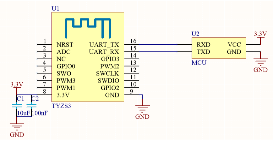
![TYZS3 Module & MCU serial communication instructions](https://airtake-public-data.oss-cn-hangzhou.aliyuncs.com/goat/20200309/16f19e4ff86d492f932b116887461c19.png)
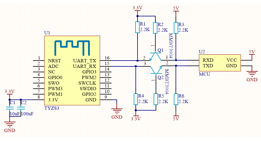
Diagram 2 MCU(5V) & Module cooperative processing mode
!![TYZS3 Module & MCU serial communication instructions](https://airtake-public-data.oss-cn-hangzhou.aliyuncs.com/goat/20200309/66bc70f478e842bf84577d98711ae4d1.png)

### Design specification <a href="#title-1-design-20specification" id="title-1-design-20specification"></a>

1.The module is under the condition of 250Kbps rate and + 19dBm transmit power， power supply consumption: 3.3V, the typical current is about 120mA. Proposed supply current≥300mA. 2. Power filter capacitor C1 & C2 should be distributed as close to the 3.3V pin as possible.C1 & C2≥10uF. 3. RESET pin is module hardware reset pin, effective under the low level. Without external circuitry, it can be directly connected to the IO port of MCU for use.

## TYZS5 Module & MCU serial communication instructions

### Typical Application diagram <a href="#title-0-typical-20application-20diagram" id="title-0-typical-20application-20diagram"></a>

Diagram 1 MCU(3.3V) & Module cooperative processing mode
![TYZS5 Module & MCU serial communication instructions](https://airtake-public-data.oss-cn-hangzhou.aliyuncs.com/goat/20200309/abbce6054c6b4d1bb8244d9512f8a187.png)

Diagram 2 MCU(5V) & Module cooperative processing mode
![TYZS5 Module & MCU serial communication instructions](https://airtake-public-data.oss-cn-hangzhou.aliyuncs.com/goat/20200309/779ac197811e472484b3e569c04a7915.png)

### Design specification <a href="#title-1-design-20specification" id="title-1-design-20specification"></a>

1.The module is under the condition of 250Kbps rate and + 19dBm transmit power， power supply consumption: 3.3V, the typical current is about 118mA. Proposed supply current≥300mA. 2. Power filter capacitor C1 & C2 should be distributed as close to the 3.3V pin as possible.C1 & C2≥10uF. 3. RESET pin is module hardware reset pin, effective under the low level. Without external circuitry, it can be directly connected to the IO port of MCU for use.

## TYZS6 Module & MCU serial communication instructions

### Typical Application diagram <a href="#title-0-typical-20application-20diagram" id="title-0-typical-20application-20diagram"></a>

Diagram 1 MCU(3.3V) & Module cooperative processing mode
![TYZS6 Module & MCU serial communication instructions](https://airtake-public-data.oss-cn-hangzhou.aliyuncs.com/goat/20200309/7cd9c9fbab4443d5acbcb03254ae6366.png)

Diagram 2 MCU(5V) & Module cooperative processing mode
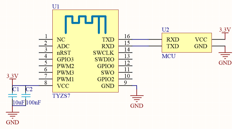
![TYZS6 Module & MCU serial communication instructions](https://airtake-public-data.oss-cn-hangzhou.aliyuncs.com/goat/20200309/1b896e37d5e44c788efce44641e496b9.png)

### Design specification <a href="#title-1-design-20specification" id="title-1-design-20specification"></a>

1.In working mode，power supply consumption: 3.3V, the typical current is about 40mA. Proposed supply current≥100mA. 2. Power filter capacitor C1 & C2 should be distributed as close to the 3.3V pin as possible.C1 & C2≥10uF. 3. nRST pin is module hardware reset pin, effective under the low level. Without external circuitry, it can be directly connected to the IO port of MCU for use.

## TYZS7 Module & MCU serial communication instructions

### Typical Application diagram <a href="#title-0-typical-20application-20diagram" id="title-0-typical-20application-20diagram"></a>

Diagram 1 MCU(3.3V) & Module cooperative processing mode
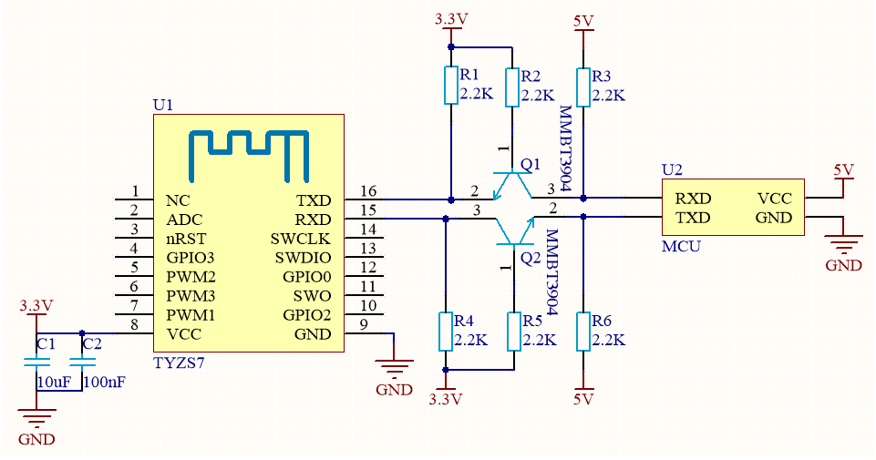
![TYZS7 Module & MCU serial communication instructions](https://airtake-public-data.oss-cn-hangzhou.aliyuncs.com/goat/20200309/8f9d98fb9507438c831c0e92a3fd8087.png)

Diagram 2 MCU(5V) & Module cooperative processing mode
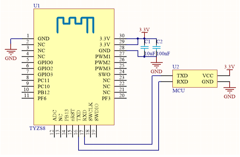
![TYZS7 Module & MCU serial communication instructions](https://airtake-public-data.oss-cn-hangzhou.aliyuncs.com/goat/20200309/9ab996103c8a4408bf2b259ba25eec87.png)

### Design specification <a href="#title-1-design-20specification" id="title-1-design-20specification"></a>

1.The module is under the condition of 250Kbps rate and + 19dBm transmit power， power supply consumption: 3.3V, the typical current is about 118mA. Proposed supply current≥300mA. 2. Power filter capacitor C1 & C2 should be distributed as close to the 3.3V pin as possible.C1 & C2≥10uF. 3. nRST pin is module hardware reset pin, effective under the low level. Without external circuitry, it can be directly connected to the IO port of MCU for use.

## TYZS8 Module & MCU serial communication instructions

### Typical Application diagram <a href="#title-0-typical-20application-20diagram" id="title-0-typical-20application-20diagram"></a>

Diagram 1 MCU(3.3V) & Module cooperative processing mode
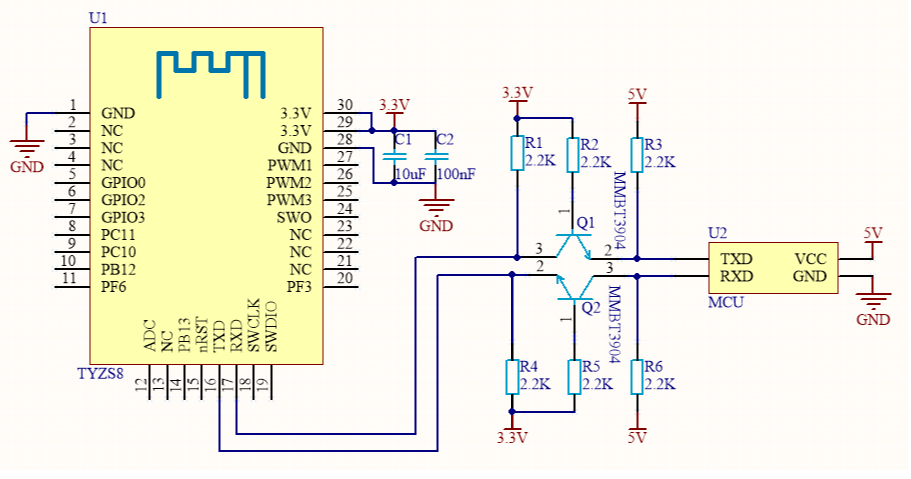
![TYZS8 Module & MCU serial communication instructions](https://airtake-public-data.oss-cn-hangzhou.aliyuncs.com/goat/20200309/bb69c56ad4d949c6a78a3ce578d46569.png)

Diagram 2 MCU(5V) & Module cooperative processing mode

![TYZS8 Module & MCU serial communication instructions](https://airtake-public-data.oss-cn-hangzhou.aliyuncs.com/goat/20200309/465116985bac4ce08c839e634ba30507.png)

### Design specification <a href="#title-1-design-20specification" id="title-1-design-20specification"></a>

1.The module is under the condition of 250Kbps rate and + 19dBm transmit power， power supply consumption: 3.3V, the typical current is about 120mA. Proposed supply current≥300mA. 2. Power filter capacitor C1 & C2 should be distributed as close to the 3.3V pin as possible.C1 & C2≥10uF. 3. nRST pin is module hardware reset pin, effective under the low level. Without external circuitry, it can be directly connected to the IO port of MCU for use.

## TYZS10 Module & MCU serial communication instructions

\## Typical Application diagram

Diagram 1 MCU(3.3V) & Module cooperative processing mode
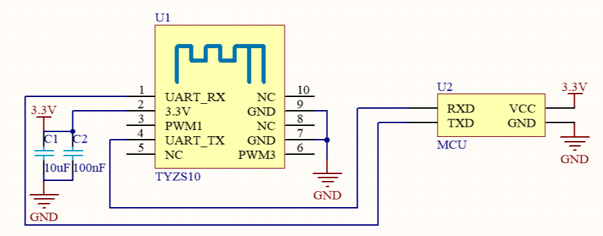
![TYZS10 Module & MCU serial communication instructions](https://airtake-public-data.oss-cn-hangzhou.aliyuncs.com/goat/20200309/609be4c333764d5b90e50324bdb7a2d1.png)

Diagram 2 MCU(5V) & Module cooperative processing mode
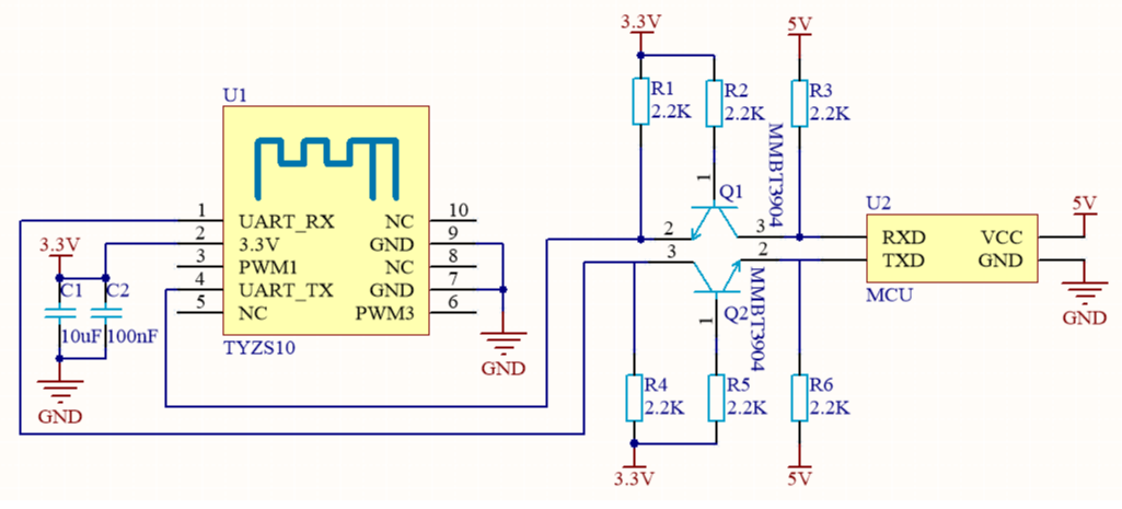
![TYZS10 Module & MCU serial communication instructions](https://airtake-public-data.oss-cn-hangzhou.aliyuncs.com/goat/20200309/63c428b5dd454d0e85745d4e52027e0e.png)

### Design specification <a href="#title-0-design-20specification" id="title-0-design-20specification"></a>

1.The module is under the condition of 250Kbps rate and + 19dBm transmit power， power supply consumption: 3.3V, the typical current is about 120mA. Proposed supply current≥300mA. 2. Power filter capacitor C1 & C2 should be distributed as close to the 3.3V pin as possible.C1 & C2≥10uF.

## TYZS11 Module & MCU serial communication instructions

### Typical Application diagram <a href="#title-0-typical-20application-20diagram" id="title-0-typical-20application-20diagram"></a>

Diagram 1 MCU(3.3V) & Module cooperative processing mode
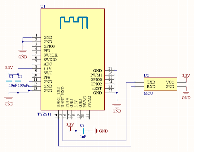
![TYZS11 Module & MCU serial communication instructions](https://airtake-public-data.oss-cn-hangzhou.aliyuncs.com/goat/20200309/ab31372d9baf4f2eb8d759c5e9fe017c.png)

Diagram 2 MCU(5V) & Module cooperative processing mode
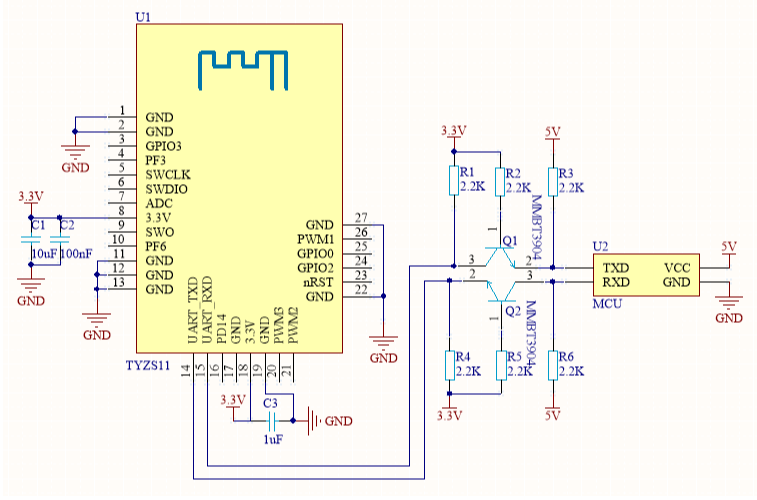
![TYZS11 Module & MCU serial communication instructions](https://airtake-public-data.oss-cn-hangzhou.aliyuncs.com/goat/20200309/4e7d4cee5bc2440ea2ad1bbf74f28284.png)

### Design specification <a href="#title-1-design-20specification" id="title-1-design-20specification"></a>

1.The module is under the condition of 250Kbps rate and + 19dBm transmit power， power supply consumption: 3.3V, the typical current is about 120mA. Proposed supply current≥300mA. 2. Power filter capacitor C1 & C2 should be distributed as close to the 3.3V pin as possible.C1 & C2≥10uF. 3. nRST pin is module hardware reset pin, effective under the low level. Without external circuitry, it can be directly connected to the IO port of MCU for use.

## TYZS12 Module & MCU serial communication instructions

### Typical Application diagram <a href="#title-0-typical-20application-20diagram" id="title-0-typical-20application-20diagram"></a>

Diagram 1 MCU(3.3V) & Module cooperative processing mode
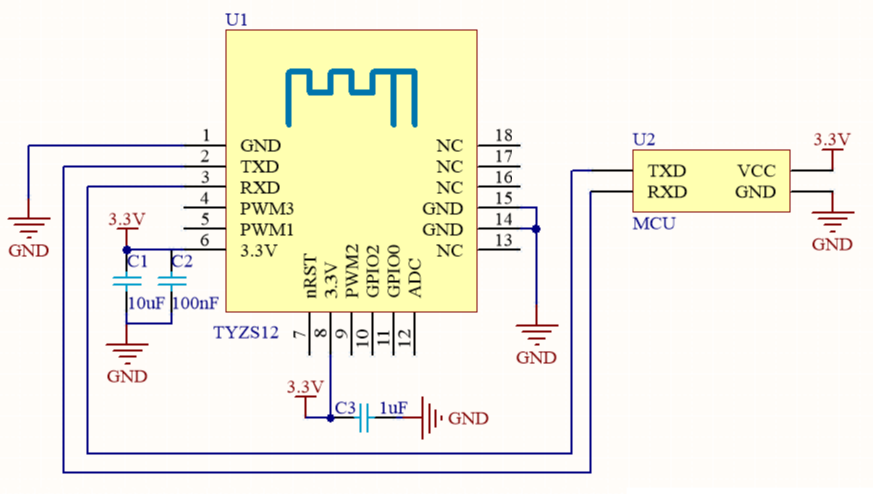
![TYZS12 Module & MCU serial communication instructions](https://airtake-public-data.oss-cn-hangzhou.aliyuncs.com/goat/20200309/559ed071f79a4348811b25926de21a70.png)

Diagram 2 MCU(5V) & Module cooperative processing mode
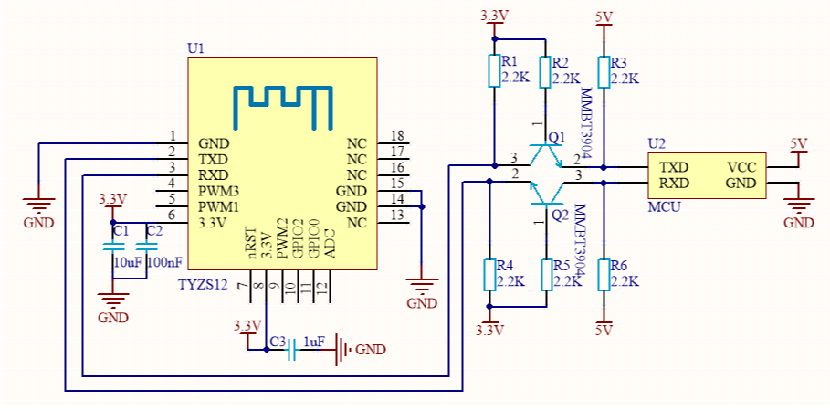
![TYZS12 Module & MCU serial communication instructions](https://airtake-public-data.oss-cn-hangzhou.aliyuncs.com/goat/20200309/094d2dd735164ce6ab6115c84233a3ca.png)

### Design specification <a href="#title-1-design-20specification" id="title-1-design-20specification"></a>

1.The module is under the condition of 250Kbps rate and + 19dBm transmit power， power supply consumption: 3.3V, the typical current is about 120mA. Proposed supply current≥300mA. 2. Power filter capacitor C1 & C2 should be distributed as close to the 3.3V pin as possible.C1 & C2≥10uF. 3. nRST pin is module hardware reset pin, effective under the low level. Without external circuitry, it can be directly connected to the IO port of MCU for use.

## TYZS13 Module & MCU serial communication instructions

### Typical Application diagram <a href="#title-0-typical-20application-20diagram" id="title-0-typical-20application-20diagram"></a>

Diagram 1 MCU(3.3V) & Module cooperative processing mode
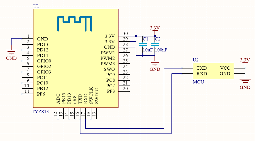
![TYZS13 Module & MCU serial communication instructions](https://airtake-public-data.oss-cn-hangzhou.aliyuncs.com/goat/20200309/c9127ab5b0c9464382cfa8114886ce0d.png)

Diagram 2 MCU(5V) & Module cooperative processing mode
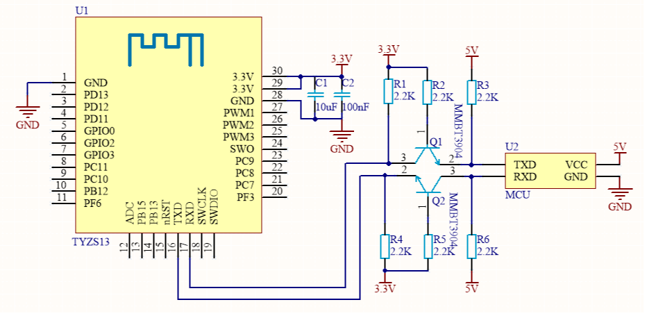
![TYZS13 Module & MCU serial communication instructions](https://airtake-public-data.oss-cn-hangzhou.aliyuncs.com/goat/20200309/1f5cef7b8ce341f2b14193d931c4e402.png)

### Design specification <a href="#title-1-design-20specification" id="title-1-design-20specification"></a>

1.The module is under the condition of 250Kbps rate and + 19dBm transmit power， power supply consumption: 3.3V, the typical current is about 120mA. Proposed supply current≥300mA. 2. Power filter capacitor C1 & C2 should be distributed as close to the 3.3V pin as possible.C1 & C2≥10uF. 3. nRST pin is module hardware reset pin, effective under the low level. Without external circuitry, it can be directly connected to the IO port of MCU for use.


# BLE General Solution


# BLE Module MCU Development Overview

## Introduction

Tuya is providing developers with MCU SDK that can be quickly programmed .This is a development kit generated automatically from the product’s function datapoint according to Tuya Serial Port Communication Protocol. MCU engineer can develop this procedure conveniently on this basis. This article will introduce you to the specific steps of MCU development.

![](https://2999784448-files.gitbook.io/~/files/v0/b/gitbook-legacy-files/o/assets%2F-MBlD-pGvqUEQDs9SdgH%2F-MBo-h_sDkpBNsnSDbD9%2F-MBo05Aqynl7dAfERBCN%2Fimage.png?alt=media\&token=07b928d0-b3b8-4666-a751-5703a3cd35ba)

> Schematic of gatewayless BLE single-point communication

![](https://2999784448-files.gitbook.io/~/files/v0/b/gitbook-legacy-files/o/assets%2F-MBlD-pGvqUEQDs9SdgH%2F-MBo-h_sDkpBNsnSDbD9%2F-MBo09-FLh6DFfYBZBFo%2Fimage.png?alt=media\&token=0af3b48e-ab16-4f4d-9859-b0a1e7c1ac10)

> Schematic of BLE single-point with gateway communication

## Development Process

The development process mainly includes: Creating products - Hardware Debugging- Software Debugging - Function Debugging.

### Creating products

Login [Tuya Smart Developer Platform](https://iot.tuya.com/) to create products. Please note that the communication type is **"BLE"**.

> Tuya BLE Standard Module includes both Non-low power and Low power mode. User can choose whether to enable the low-power function through protocol instructions.
>
> * Non-low power mode is for products with long power supply and insensitive to power consumption.
> * Low power mode is for battery-powered products with higher power consumption requirements.

After the product is created, users can select functions, panels, modules and firmware according to the actual needs of the product, and download the corresponding MCU development kit.

Creating a product is described in detail in the [MCU Access Guide](https://docs.tuya.com/en/iot/device-development/access-mode-mcu/mcu-access-guide/mcu-access-guide), so we won't go into details here.

![](https://2999784448-files.gitbook.io/~/files/v0/b/gitbook-legacy-files/o/assets%2F-MBlD-pGvqUEQDs9SdgH%2F-MBo-h_sDkpBNsnSDbD9%2F-MBo0HeIi2nE3rjPB8vu%2Fimage.png?alt=media\&token=9468613b-86c9-430e-a652-ca25f7fb820e)

### Hardware Debugging

When selecting module on the platform, the platform will recommend some common module models. After selecting the module and firmware, you can purchase module samples online.

The hardware engineer can enter the drawing board stage, and the related materials for hardware development can be viewed in the developer center:

Data manual link: [BLE module datasheet](https://docs.tuya.com/en/iot/device-development/module/ble-module/br3l);

Hardware design guidance: [BLE module hardware design](https://docs.tuya.com/zh/iot/device-development/access-mode-mcu/ble-general-solution/ble-hardware-design/tybt3)(not available now);

PCB data: [Common module package library](https://pan.baidu.com/s/10xJBTxyDQjweUI6C6LhrNQ).

**Note**: When the battery is used as the power supply, when the power supply voltage is lower than the normal working voltage, the internal flash operation of the module will risk the error, causing the firmware or user data to be modified abnormally.

You can choose 2 way to rescue it: 1.When the MCU detects that the battery voltage is too low, cut off the module's power.

2.When the MCU detects that the battery voltage is too low, turn off the broadcast and system timing, put module in deep sleep mode. The minimum working voltage of Telink module is 1.8V, MCU can be set at 2.0V (slightly higher than 1.8V).

#### Network verification

After getting the module, you don't need to write code first, first determine whether the module is working properly. Using the module debugging assistant (MCU simulation mode) provided by Tuya to cooperate with the module can perform network config operation, verify the module and be familiar with the protocol interaction process at the same time, and the development and debugging efficiency will be greatly improved later.

The framework of Tuya BLE Standard Serial Communication Protocol is shown below：

![](https://2999784448-files.gitbook.io/~/files/v0/b/gitbook-legacy-files/o/assets%2F-MBlD-pGvqUEQDs9SdgH%2F-MBo-h_sDkpBNsnSDbD9%2F-MBo0PEqX8yMjEYAyqCT%2Fimage.png?alt=media\&token=5a7b42e4-0f95-4348-9e85-164378c9ac97)

**Low-power Mode Control Pin**: At present, It's necessary required in Scheme of Standard Door Lock (TYBN1,BK3431Q), and it needs to be connected and used by MCU. For other standard scheme, to use the low-power mode, you must also connect the module's Low-power Control Part. If you don't need this mode, it's enough to just finish the basic connection part.

**Status of Connection Notification Pin**: In Low-power Mode, the GPIO will output high level when BLE connection with Mobile is successful. And when it's disconnected, the Pin will output low level.

> **Note**: Some module does not supply this function. For details, please refer to the Low-power Mode section of the protocol document (optional, different models have different screen printing, see the datasheet for details.

Tuya MCU simulation debugging assistant, the assistant can simulate MCU data transmission and reception. Set up the minimum system of the module and connect the serial port to the computer.The assistant has the following functions: 1. Pair with a networked module and verify that the module is working properly. 2. Before the MCU completes development, debug the App panel display. 3. When the MCU developer does not know how to send and reply data to the module, the data of the simulation assistant can be used as a reference.

For more information, please refer to the [Module Debugging Assistant Instruction](https://docs.tuya.com/en/iot/device-development/access-mode-simmulator/access-mode-mdodule-simmulator)

![](https://2999784448-files.gitbook.io/~/files/v0/b/gitbook-legacy-files/o/assets%2F-MBlD-pGvqUEQDs9SdgH%2F-MBo-h_sDkpBNsnSDbD9%2F-MBo0V3akiXmhmBjvVs7%2Fimage.png?alt=media\&token=0c93a169-53d2-444b-b05e-f076e99b2234)

> Module Debugging Assistant (MCU simulation mode)

**step1.** According to the minimum system schematic diagram, build the module peripheral circuit, simple test can fly wire directly.

**step2.** Open the Tuya module debugging assistant in the development kit and import the debugging file. Protocol selection BLE single point general protocol, MCU simulation mode.

**step3.** Connect the module serial port to the computer through the USB to TTL tool. The assistant selects the corresponding serial port and baud rate. Open the serial port and click Start. You will see that the module and the host computer automatically perform the initialization process protocol interaction.

**Note：** After the Bluetooth module is powered on, it will continuously send heartbeat packets. After receiving the correct response, it will perform subsequent initialization protocol interactions. If no data is sent after power on, please check if the peripheral circuit of the module is correct.

**step4.** Click Reset Module, the module will disconnect the BLE connection of the module, release the BLE binding relationship, clear the module's cache information, and restart the module.

![](https://2999784448-files.gitbook.io/~/files/v0/b/gitbook-legacy-files/o/assets%2F-MBlD-pGvqUEQDs9SdgH%2F-MBo-h_sDkpBNsnSDbD9%2F-MBo0_hde3kgpw-p9dbT%2Fimage.png?alt=media\&token=13389b16-4104-46d3-b99f-f5c2e22310e0)

### Software Debugging

During hardware debugging, you can see that the module and the MCU have a series of serial protocol interaction data. For the data analysis part, users can refer to the protocol document in the development kit. The agreement is mainly divided into two parts: the basic protocol and the functional protocol.

The basic protocol has nothing to do with the product. It is a common protocol of the module, including module initialization instructions and some extended function instructions.

The functional protocol part is mainly based on the reporting and issuing command words of the basic protocol, and details the format of the Datapoint content. The full content of the basic protocol, the document center is kept updated in real time, you can click the link to view: [Tuya Cloud BLE Universal Serial Port Access Protocol](https://docs.tuya.com/en/iot/device-development/access-mode-mcu/ble-general-solution/tuya-cloud-universal-serial-port-access-protocol/tuya-cloud-universal-serial-port-access-protocol)(not available now).

There are two ways for the MCU to connect with the Tuya module protocol: transplant the MCU SDK or connect the protocol by yourself.

* Connect protocol by yourself:

  When the MCU resources are limited or the MCU SDK is not suitable for porting, customers can choose to connect the serial port protocol by themselves.
* Transplant MCU SDK:

  If the MCU resources are sufficient, it is generally recommended that users directly port the MCU SDK for efficient and convenient development. The MCU SDK in the development kit is a C-based protocol application code provided by Tuya, which can be directly added to the MCU project.

  The MCU SDK requires MCU hardware resources: Flash 4K bytes; RAM is related to the length of the DataPoint, about 100 bytes (if OTA function is required, it must be bigger than 260 bytes); the number of function nesting levels is 9 levels. If users with insufficient resources can connect the protocol by themselves, the functions in the SDK package can still be used as a reference.

  For details can see: [Overview of migrating Tuya's MCU SDK](https://docs.tuya.com/en/iot/device-development/access-mode-mcu/software-reference-wifi/overview-of-migrating-tuyas-mcu-sdk).

### Functions Debugging

After porting the MCU SDK code development, you can use the Tuya module debugging assistant - module simulation mode to verify the correctness of the MCU code. The usage method is similar to the MCU simulation mode. In the simulation module mode, the assistant will automatically send the initialization data stream to verify that the MCU response is correct and give corresponding prompts for the incorrect data. After the initial interaction is passed, you can manually click to test other extended functions.

**Note：** module simulation mode do not supply network functions, only used to verify the correctness of the MCU serial protocol transmission and reception. After the test is completed, the MCU can be connected to the actual module and test the network.

![](https://2999784448-files.gitbook.io/~/files/v0/b/gitbook-legacy-files/o/assets%2F-MBlD-pGvqUEQDs9SdgH%2F-MBo-h_sDkpBNsnSDbD9%2F-MBo0fCzIBMllbCrSDVu%2Fimage.png?alt=media\&token=1c5b070e-9b77-4004-acb2-cb6d2e5b5870)

> Module Debugging Assistant (Module simulation mode)

![](https://2999784448-files.gitbook.io/~/files/v0/b/gitbook-legacy-files/o/assets%2F-MBlD-pGvqUEQDs9SdgH%2F-MBo-h_sDkpBNsnSDbD9%2F-MBo0jsKaBrL15O_Hgrt%2Fimage.png?alt=media\&token=6499020c-7e8d-4857-ae35-db3590347c54)

Other Debugging Common Tools Links：

[Operations Center Guide](https://docs.tuya.com/en/iot/guidelines-for-platform/operation-center/operation#%E8%AE%BE%E5%A4%87%E6%97%A5%E5%BF%97%E6%9F%A5%E8%AF%A2%EF%BC%88%E6%94%AF%E6%8C%81%E5%8D%95%E4%B8%AA%E8%AE%BE%E5%A4%87%E4%BD%BF%E7%94%A8%E8%A1%8C%E4%B8%BA%E6%9F%A5%E8%AF%A2%EF%BC%89)：Tuya Smart Developer Platform - Operation. You can check device background log here according to your product id.

[Tutorial for Tuya Support Center](https://docs.tuya.com/en/iot/guidelines-for-platform/support-center/troubleshooting)：Tuya provide online technical support, you can ask any questions like the question about documents here.

[FAQ](https://docs.tuya.com/en/iot/device-development/access-mode-mcu/ble-general-solution/faq-collection-for-open-platform/faq-collection-for-open-platform)(not available now)：FAQ, you can read it before developing to avoid some problem.


# BLE Hardware Design

## TYBT3 Module & MCU serial communication instructions

### Typical Application diagram <a href="#title-0-typical-20application-20diagram" id="title-0-typical-20application-20diagram"></a>

Diagram 1 MCU(3.3V) & Module cooperative processing mode
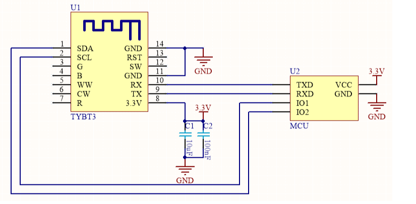
![TYBT3 Module & MCU serial communication instructions](https://airtake-public-data-1254153901.cos.ap-shanghai.myqcloud.com/goat/20200509/10e457e5656a44888b3acc77a6ed0264.png)

Diagram 2 MCU(5V) & Module cooperative processing mode
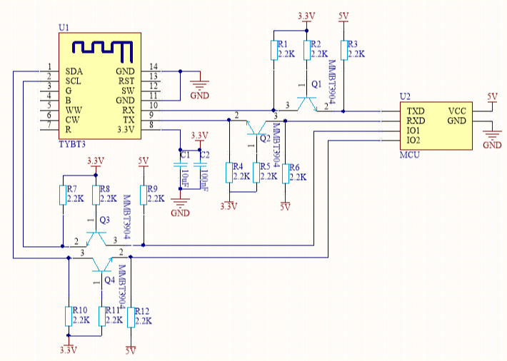
![TYBT3 Module & MCU serial communication instructions](https://airtake-public-data-1254153901.cos.ap-shanghai.myqcloud.com/goat/20200509/52f286f76efc45a391db2a755d74e61b.png)

### Design specification <a href="#title-1-design-20specification" id="title-1-design-20specification"></a>

1.The power supply consumption: 3.3V,proposed supply current≥100mA. 2. Power filter capacitor C1 & C2 should be distributed as close to the 3.3V pin as possible.C1 & C2≥10uF. 3. RST pin is module hardware reset pin, effective under the low level. Without external circuitry, it can be directly connected to the IO port of MCU for use. 4. The SDA pin is the low power control pin, the MCU sends and the module receives. 5. The SCL pin is the connection status indicator pin, the module sends and the MCU receives.

## TYBT4 Module & MCU serial communication instructions

### Typical Application diagram <a href="#title-0-typical-20application-20diagram" id="title-0-typical-20application-20diagram"></a>

Diagram 1 MCU(3.3V) & Module cooperative processing mode

![TYBT4 Module & MCU serial communication instructions](https://airtake-public-data.oss-cn-hangzhou.aliyuncs.com/goat/20200309/5e4c220a61974f9bb750087450fe6a53.png)

Diagram 2 MCU(5V) & Module cooperative processing mode

![TYBT4 Module & MCU serial communication instructions](https://airtake-public-data.oss-cn-hangzhou.aliyuncs.com/goat/20200309/dc66da7113c440c18693d8a3b5435b65.png)

### Design specification <a href="#title-1-design-20specification" id="title-1-design-20specification"></a>

1.The power supply consumption: 3.3V,proposed supply current≥100mA. 2. Power filter capacitor C1 & C2 should be distributed as close to the 3.3V pin as possible.C1 & C2≥10uF. 3. RST pin is module hardware reset pin, effective under the low level. Without external circuitry, it can be directly connected to the IO port of MCU for use.

## TYBN1 Module & MCU serial communication instructions

### Typical Application diagram <a href="#title-0-typical-20application-20diagram" id="title-0-typical-20application-20diagram"></a>

Diagram 1 MCU(3.3V) & Module cooperative processing mode

![TYBN1 Module & MCU serial communication instructions](https://airtake-public-data-1254153901.cos.ap-shanghai.myqcloud.com/goat/20200511/ba922351b222445b8fc7e75a56912ebd.png)

Diagram 2 MCU(5V) & Module cooperative processing mode

![TYBN1 Module & MCU serial communication instructions](https://airtake-public-data-1254153901.cos.ap-shanghai.myqcloud.com/goat/20200511/383a908909e34a5caafe8d3af8830882.png)

### Design specification <a href="#title-1-design-20specification" id="title-1-design-20specification"></a>

1.The power supply consumption: 3.3V,proposed supply current≥100mA. 2. Power filter capacitor C1 & C2 should be distributed as close to the 3.3V pin as possible.C1 & C2≥10uF. 3. RST pin is module hardware reset pin, effective under the low level. Without external circuitry, it can be directly connected to the IO port of MCU for use. 4. The IO11 pin is the low power control pin, the MCU sends and the module receives. 5. The IO14 pin is the "module wakes up MCU" pin, the module sends and the MCU receives.

## BT3L Module & MCU serial communication instructions

### Typical Application diagram <a href="#title-0-typical-20application-20diagram" id="title-0-typical-20application-20diagram"></a>

Diagram 1 MCU(3.3V) & Module cooperative processing mode
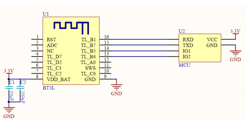
![BT3L Module & MCU serial communication instructions](https://airtake-public-data-1254153901.cos.ap-shanghai.myqcloud.com/goat/20200511/9bec6f0f31754ed290bc846133597c79.png)![BT3L Module & MCU serial communication instructions](https://airtake-public-data.oss-cn-hangzhou.aliyuncs.com/goat/20200309/97a72ab00d6f47b18a0948aeada13f25.png)

Diagram 2 MCU(5V) & Module cooperative processing mode
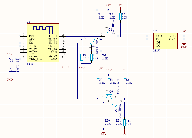
![BT3L Module & MCU serial communication instructions](https://airtake-public-data-1254153901.cos.ap-shanghai.myqcloud.com/goat/20200511/dbdf63ca775d4404865b74b3852cf19e.png)

### Design specification <a href="#title-1-design-20specification" id="title-1-design-20specification"></a>

1.The power supply consumption: 3.3V,proposed supply current≥100mA. 2. Power filter capacitor C1 & C2 should be distributed as close to the 3.3V pin as possible.C1 & C2≥10uF. 3. RST pin is module hardware reset pin, effective under the low level. Without external circuitry, it can be directly connected to the IO port of MCU for use. 4. The TL\_B5 pin is the low power control pin, the MCU sends and the module receives. 5. The TL\_B4 pin is the connection status indicator pin, the module sends and the MCU receives.

## TYBT5 Module & MCU serial communication instructions

### Typical Application diagram <a href="#title-0-typical-20application-20diagram" id="title-0-typical-20application-20diagram"></a>

Diagram 1 MCU(3.3V) & Module cooperative processing mode
![TYBT5 Module & MCU serial communication instructions](https://airtake-public-data-1254153901.cos.ap-shanghai.myqcloud.com/goat/20200511/3dfb033b43654044a775dc3d89a70bfa.png)

Diagram 2 MCU(5V) & Module cooperative processing mode
![TYBT5 Module & MCU serial communication instructions](https://airtake-public-data-1254153901.cos.ap-shanghai.myqcloud.com/goat/20200511/52bc39a4bace40c884dbf611ec12062e.png)

### Design specification <a href="#title-1-design-20specification" id="title-1-design-20specification"></a>

1.The power supply consumption: 3.3V,proposed supply current≥100mA. 2. Power filter capacitor C1 & C2 should be distributed as close to the 3.3V pin as possible.C1 & C2≥10uF. 3. RST pin is module hardware reset pin, effective under the low level. Without external circuitry, it can be directly connected to the IO port of MCU for use. 4. The IIC\_SDA pin is the low power control pin, the MCU sends and the module receives. 5. The IIC\_SCL pin is the connection status indicator pin, the module sends and the MCU receives.

## BT7L Module & MCU serial communication instructions

### Typical Application diagram <a href="#title-0-typical-20application-20diagram" id="title-0-typical-20application-20diagram"></a>

Diagram 1 MCU(3.3V) & Module cooperative processing mode

![BT7L Module & MCU serial communication instructions](https://airtake-public-data-1254153901.cos.ap-shanghai.myqcloud.com/goat/20200612/99cb92e0b2714159bc8a4b7770c7574c.png)

Diagram 2 MCU(5V) & Module cooperative processing mode

![BT7L Module & MCU serial communication instructions](https://airtake-public-data-1254153901.cos.ap-shanghai.myqcloud.com/goat/20200612/6a9045d34b16477599e93d1effc53229.png)

### Design specification <a href="#title-1-design-20specification" id="title-1-design-20specification"></a>

1.The power supply consumption: 3.3V,proposed supply current≥100mA. 2. Power filter capacitor C1 & C2 should be distributed as close to the 3.3V pin as possible.C1 & C2≥10uF. 3. RST pin is module hardware reset pin, effective under the low level. Without external circuitry, it can be directly connected to the IO port of MCU for use. 4. The B5 pin is the low power control pin, the MCU sends and the module receives. 5. The B4 pin is the connection status indicator pin, the module sends and the MCU receives.


# NB-IoT General Solution


# NB-IoT Development Guide

## Background <a href="#title-0-background" id="title-0-background"></a>

The Narrow Band Internet of Things (NB-IoT) is built on cellular mobile communication network to achieve thing-to-thing communication and thing-to-person communication. NB-IoT focuses on the Low Power Wide Area (LPWA) Internet of Things (IoT) market.

The NB-IoT network consumes only about 180 kHz of bandwidth. Using the License frequency band, three deployment methods such as in-band, guard band, or independent carrier can be used to coexist with the existing network. Can be directly deployed on GSM, UMTS or LTE networks to reduce deployment costs and achieve smooth upgrades.

#### NB-IoT Features <a href="#subtitle-1-nb-iot-20features" id="subtitle-1-nb-iot-20features"></a>

* **Low-power**: IoT Products(such as smart meter reading, environmental monitoring, smart agriculture, etc.) have no power supply in the installation environment and require batteries. In order to meet the battery's 5 to 10-year life expectancy, the NB-IoT network introduced PSM and eDRX technology. It greatly reduces the power consumption of the terminal, which can keep the device in a very low power consumption state for most of the life cycle, thereby ensuring the battery life.
* **Low-cost**: NB-IoT Products use narrow-band technology, low baseband complexity, only use a single antenna, adopt half-duplex mode, low cost of RF module, most unnecessary functions (SRVCC, IMS, emergency call, etc.) are cut and the use of the SoC's built-in power amplifier PA reduce the requirements for terminal flash storage space, terminal size, terminal radio frequency, etc., thereby greatly reducing the cost of NB-IoT.
* **Large number of connections**: NB-IoT has 50-100 times higher uplink capacity than 2G / 3G / 4G (specific service model). NB-IoT can provide 50-100 times the number of accesses than existing wireless technologies. A single cell can support 5 10,000-level user scale.
* **Wide coverage**: 164db MCL, NB-IoT improves 20db gain over GPRS, it can cover well in places where signals such as underground garages, basements, and underground pipes are difficult to reach.

| Features                   | Details                                                                                             | Specific value range                                                                                                                                                                                                                      |
| -------------------------- | --------------------------------------------------------------------------------------------------- | ----------------------------------------------------------------------------------------------------------------------------------------------------------------------------------------------------------------------------------------- |
| Less data                  | Limited Air Interface resources (180khz), suitable for small data communication                     | 50 \~ 200 bytes is suitable, the smaller the better                                                                                                                                                                                       |
| Low frequency, long period | Most terminals should be in a dormant state for a long time, the frequency of reporting data is low | Report by day, 1-2 times per day is more appropriate. High frequency reporting (for example, 30 minutes), will occupy a large amount of network capacity. The higher the reporting frequency, the greater the impact on network capacity. |
| Low power consumption      | Lowest power consumption in PSM mode                                                                | Power sensitive applications preferably                                                                                                                                                                                                   |
| Slow mobility              | Suitable for slow mobility                                                                          | Movement speed is less than 30km/h                                                                                                                                                                                                        |
| Wide coverage              | Batter coverage                                                                                     | Can support scene coverage like basement                                                                                                                                                                                                  |
| Low rate                   | The theoretical peak rate of upstream is 15.6kbps, theoretical peak rate of downstream is 21.25kbps | Bandwidth high-rate services cannot be carried by NB-IoT network                                                                                                                                                                          |

![](https://2999784448-files.gitbook.io/~/files/v0/b/gitbook-legacy-files/o/assets%2F-MBlD-pGvqUEQDs9SdgH%2F-MBo0nxSpkUN4cy-GLhA%2F-MBo20R54KNvw_jFqP45%2Fimage.png?alt=media\&token=94860b7a-38da-482e-b9b6-cfb301c1d6fa)

#### NB-IoT Network Structure <a href="#subtitle-2-nb-iot-20network-20structure" id="subtitle-2-nb-iot-20network-20structure"></a>

The NB-IoT network consists of NB-IoT terminals, NB-IoT base stations, NB-IoT packet core networks, IoT connection management platforms, and industry application servers. The access network architecture of NB-IoT is the same as that of LTE.

#### Power-saving Mode <a href="#subtitle-3-power-saving-20mode" id="subtitle-3-power-saving-20mode"></a>

> The development of NB-IoT business scale is closely related to the bearer business model, and its applicable scenarios are "small traffic, reporting-oriented, long-term sleep, power consumption sensitive, low mobility" applications. In order to realize the large number of low-power devices carried by the NB-IoT network, the most important technologies are: PSM and eDRX

NB-IoT supports 3 power-saving modes: **PSM** (Power Saving Mode), **DRX** (Discontinuous Reception), **eDRX** (Extended DRX)

#### PSM Mode <a href="#subtitle-4-psm-20mode" id="subtitle-4-psm-20mode"></a>

The terminal is deeply dormant during non-business periods and does not receive downlink data. Only the terminal can actively receive the downlink data buffered by the IoT platform when it actively sends uplink data (MO Data).

In this mode, the radio frequency of the terminal is turned off, which is equivalent to the shutdown state, but the core network side still retains the user context. When the user enters the idle state / connected state, there is no need to attach the PDN to establish it.

It is suitable for services with no delay requirements for downlink data; terminal equipment has low power consumption and uses battery-powered methods, such as meter reading services.

![](https://2999784448-files.gitbook.io/~/files/v0/b/gitbook-legacy-files/o/assets%2F-MBlD-pGvqUEQDs9SdgH%2F-MBo0nxSpkUN4cy-GLhA%2F-MBo25XlR2REddOzYr7I%2Fimage.png?alt=media\&token=00bc4cc9-366c-4168-bcb7-1e46f2008157)

State:

* Active: The module is in an active state; all functions are normally available and data can be sent and received; the module can switch to Idle mode or PSM mode in this mode.
* Idle: The module is in a light sleep state; the module can receive paging messages in network connected state. Module can switch to Active or PSM mode in this mode.
* PSM: The module is in a deep sleep state, only the RTC works internally, the network is in a disconnected state and it cannot receive paging messages. When the timer expires, the module will be woken up; the module can also be woken up by pulling down the PSM\_EINT pin.

![](https://2999784448-files.gitbook.io/~/files/v0/b/gitbook-legacy-files/o/assets%2F-MBlD-pGvqUEQDs9SdgH%2F-MBo0nxSpkUN4cy-GLhA%2F-MBo2BI-HbTkT8SYItr0%2Fimage.png?alt=media\&token=c7f6e38e-3417-466b-89b6-08f7449a5583)

#### eDRX Mode <a href="#subtitle-5-edrx-20mode" id="subtitle-5-edrx-20mode"></a>

The terminal equipment takes into account both low-power consumption and services with certain delay requirements. In each eDRX cycle, the terminal can receive downlink data only within the set paging time window, the rest of the time the terminal is in a sleep state and does not receive downlink data. This mode can achieve a balance between downlink service delay and power consumption, such as remotely shutting down the gas service.

![](https://2999784448-files.gitbook.io/~/files/v0/b/gitbook-legacy-files/o/assets%2F-MBlD-pGvqUEQDs9SdgH%2F-MBo0nxSpkUN4cy-GLhA%2F-MBo2HwbjfM6kB86A-iJ%2Fimage.png?alt=media\&token=1898be88-cabc-437b-bc7e-a3d978626eac)

Within each eDRX cycle, there is a paging time window (PTW). The terminal monitors the paging channel in the PTW according to the DRX cycle (the DRX cycle time is short, the terminal can be considered not to sleep and always reachable) in order to receive downlink Data, the rest of the time the terminal is dormant. The eDRX mode can be considered that the terminal equipment is reachable at any time, but the delay is large. The delay depends on the eDRX cycle configuration, which can achieve a balance between low power consumption and delay.

#### DRX Mode <a href="#subtitle-6-drx-20mode" id="subtitle-6-drx-20mode"></a>

It can be considered that the downlink service can reach the terminal equipment at any time. In each DRX cycle, the terminal detects whether a downlink service arrives once, which is suitable for services with high requirements on delay. Terminal equipment generally adopts power supply methods, such as street light services.

![](https://2999784448-files.gitbook.io/~/files/v0/b/gitbook-legacy-files/o/assets%2F-MBlD-pGvqUEQDs9SdgH%2F-MBo0nxSpkUN4cy-GLhA%2F-MBo2L4tM2M9YQvQZoJT%2Fimage.png?alt=media\&token=0ebc43c8-8ad8-45de-a767-683d31dc177e)

Due to the short DRX cycle (1.28s, 2.56s, 5.12s, or 10.24s, which is determined by the operator's network settings and depends on the APN service handled by SIM), it can be considered that downlink services are always available and the delay is small. It is suitable for services that have high requirements on delay, but the power consumption is relatively high. Terminal equipment generally uses the mains power supply method.

#### NB-IoT Latency <a href="#subtitle-7-nb-iot-20latency" id="subtitle-7-nb-iot-20latency"></a>

First time network access latency: After the NB-IoT terminal is turned on, the terminal has a lot of message interaction with the network (authentication, channel establishment, IP address allocation, etc.). It takes 6-8s to complete network access and obtain an IP address Used for later data transmission.

Data reporting and reception latency: After the NB terminal is successfully connected, when the terminal has data transmission, the terminal will actively establish a wireless connection with the base station (no authentication, IP address allocation and other processes are required at this time). Then send the data immediately. The delay of data reporting by the terminal is closely related to the state of the terminal and the wireless network coverage.

| Data reported by the terminal                                | Data issued by the platform(PSM)                                                                       | Data issued by the platform(DRX)                                                             | Data issued by the platform(eDRX)                                                          |
| ------------------------------------------------------------ | ------------------------------------------------------------------------------------------------------ | -------------------------------------------------------------------------------------------- | ------------------------------------------------------------------------------------------ |
| Air interface delay + private network to client server delay | Air interface delay + private network to platform delay + PSM maximum sleep period (maximum 310 hours) | Air interface delay (750ms) + DRX paging cycle (maximum 10.24 seconds, minimum 1.28 seconds) | Air interface delay (750ms) + eDRX paging cycle (maximum 2.92 hours, minimum 5.12 seconds) |
| Seconds (3 to 30 seconds)                                    | Hour / day, depending on the reporting period of the terminal                                          | Seconds, depending on the DRX paging cycle                                                   | Seconds and hours, depending on eDRX paging cycle                                          |

#### NB-IoT Key Parameters <a href="#subtitle-8-nb-iot-20key-20parameters" id="subtitle-8-nb-iot-20key-20parameters"></a>

The low-power consumption mechanism of the NB application is inseparable from the configuration of the SIM card operator. Therefore, when purchasing SIM cards, please be clear about the APN business you handle. Different APNs are suitable for different application scenarios.

> If you have any problem about how to choose APN business, please ask Tuya stuff.

#### NB-IoT Power Consumption <a href="#subtitle-9-nb-iot-20power-20consumption" id="subtitle-9-nb-iot-20power-20consumption"></a>

| State      | Power consumption               | Measured results                |
| ---------- | ------------------------------- | ------------------------------- |
| PSM        | 3 uA                            | 2.7 uA                          |
| eDRX       | xxuA\~2 mA                      | 1 mA                            |
| DRX        | 1\~4mA                          | 1mA                             |
| Connectted | Sending 200 mA, receiving 65 mA | Sending 189mA, receiving 161 mA |

## Tuya MCU Solution Introduction <a href="#title-1-tuya-20mcu-20solution-20introduction" id="title-1-tuya-20mcu-20solution-20introduction"></a>

The Narrow Band Internet of Things (NB-IoT) is built on cellular mobile communication network to achieve thing-to-thing communication and thing-to-person communication. NB-IoT focuses on the Low Power Wide Area (LPWA) Internet of Things (IoT) market.

The NB-IoT network consumes only about 180 kHz of bandwidth. Using the License frequency band, three deployment methods such as in-band, guard band, or independent carrier can be used to coexist with the existing network. Can be directly deployed on GSM, UMTS or LTE networks to reduce deployment costs and achieve smooth upgrades.

Tuya is providing developers with MCU SDK that can be quickly programmed .This is a development kit generated automatically from the product’s function datapoint according to Tuya Serial Port Communication Protocol. MCU engineer can develop this procedure conveniently on this basis. This article will introduce you to the specific steps of MCU development.

## Development Process <a href="#title-2-development-20process" id="title-2-development-20process"></a>

The development process mainly includes: Creating products - Hardware debugging-software debugging - function debugging.

### Creating products <a href="#title-3-creating-20products" id="title-3-creating-20products"></a>

Login [Tuya Smart Developer Platform](https://iot.tuya.com/) to create products. Please note that the communication type is **"NB-IoT"**, The type of power consumption is selected based on the characteristics of the product. For common battery-powered, monitoring and reporting services, please select **"PSM"**. For products that are not sensitive to power consumption and deliver controlled services, please select **"DRX"** (note that the choice of power consumption will affect the sending and production of subsequent modules).

After the product is created, users can select functions, panels, modules and firmware according to the actual needs of the product, and download the corresponding MCU development kit.

![](https://2999784448-files.gitbook.io/~/files/v0/b/gitbook-legacy-files/o/assets%2F-MBlD-pGvqUEQDs9SdgH%2F-MBo0nxSpkUN4cy-GLhA%2F-MBo2Tu59nUjb0wvjBz9%2Fimage.png?alt=media\&token=06755fd3-2336-44dd-8b80-7ee090dc1730)

Creating a product is described in detail in the [MCU Access Guide](https://docs.tuya.com/en/iot/device-development/access-mode-mcu/mcu-access-guide/mcu-access-guide), so we won't go into details here.

### Hardware Debugging <a href="#title-4-hardware-20debugging" id="title-4-hardware-20debugging"></a>

When selecting module on the platform, the platform will recommend some common module models. After selecting the module and firmware, you can purchase module samples online.

The hardware engineer can enter the drawing board stage, and the related materials for hardware development can be viewed in the developer center:

Data manual link: [NB-IoT module datasheet](https://docs.tuya.com/en/iot/device-development/module/nb-module/nm1)(not available now);

Hardware design guidance: [NM1 module hardware design](https://docs.tuya.com/zh/iot/device-development/access-mode-mcu/nbiot-general-solution/nbguide)(not available now);

PCB data: [Common module package library](https://pan.baidu.com/s/10xJBTxyDQjweUI6C6LhrNQ).

**Note**: The peak working current of the NB-IoT universal module will reach more than 300mA. Be sure to leave a margin when designing the power supply.

#### Build Minimal Hardware System <a href="#subtitle-14-build-20minimal-20hardware-20system" id="subtitle-14-build-20minimal-20hardware-20system"></a>

![](https://2999784448-files.gitbook.io/~/files/v0/b/gitbook-legacy-files/o/assets%2F-MBlD-pGvqUEQDs9SdgH%2F-MBo0nxSpkUN4cy-GLhA%2F-MBo2_IYeB9qPCIdl5wr%2Fimage.png?alt=media\&token=f281fd74-f8a4-4368-a9d4-78f2dafbbecf)

* Serial communication circuit-serial level 1.8V, level conversion required

  * UART0: module firmware programming pin, which is generally not used in the solution connection process, which can connect to test point debug (baud rate 115200)
  * UART1 (commonly used): Universal docking pin, used for serial communication between module and user chip (baud rate 115200 or 9600)
  * UART2: Log print pin, used to find problems in the docking process. It needs to be used for collaborative judgment by grabbing logs, which can connect to test point debugging. (Baud rate 921600)

* Module wake-up circuit：
  * Power-on wake-up pin： PWRKEY
  * Low-power consumption mode wake-up pin： PSM\_EINT

* Sim card circuit： Determine SIM Encapsulation useing USIM or eSIM before designing (Will purchase SIM card according to product features)

* Power supply circuit： The peak working current of the NB-IoT universal module will reach more than 300mA. Be sure to leave a margin when designing the power supply

* Antenna circuit： Antenna RF circuit can refer to the hardware design manual (The antenna needs to communicate to the antenna manufacturer for matching.)

![](https://2999784448-files.gitbook.io/~/files/v0/b/gitbook-legacy-files/o/assets%2F-MBlD-pGvqUEQDs9SdgH%2F-MBo0nxSpkUN4cy-GLhA%2F-MBo2efQl70Lj0ElxHay%2Fimage.png?alt=media\&token=6b46607e-648d-4068-8789-ff3487194896)

#### Network verification <a href="#subtitle-15-network-20verification" id="subtitle-15-network-20verification"></a>

After getting the module, you don't need to write code first, first determine whether the module is working properly. Using the module debugging assistant (MCU simulation mode) provided by Tuya to cooperate with the module can perform network config operation, verify the module and be familiar with the protocol interaction process at the same time, and the development and debugging efficiency will be greatly improved later.

Tuya MCU simulation debugging assistant can simulate MCU data transmission and reception. Set up the minimum system of the module and connect the serial port to the computer. The assistant has the following functions: 1. Pair with a networked module and verify that the module is working properly. 2. Before the MCU completes development, debug the App panel display. 3. When the MCU developer does not know how to send and reply data to the module, the data of the simulation assistant can be used as a reference.

For more information, please refer to the [Module Debugging Assistant Instruction](https://docs.tuya.com/en/iot/device-development/access-mode-simmulator/access-mode-mdodule-simmulator)

![](https://2999784448-files.gitbook.io/~/files/v0/b/gitbook-legacy-files/o/assets%2F-MBlD-pGvqUEQDs9SdgH%2F-MBo0nxSpkUN4cy-GLhA%2F-MBo2jVS8SoCTJfPZ9kX%2Fimage.png?alt=media\&token=09e7b8ca-1d44-46a8-9276-98e8ae1f8f22)

> Module Debugging Assistant (MCU simulation mode)

**step1.** According to the minimum system schematic diagram, build the module peripheral circuit, simple test can fly wire directly.

**step2.** Open the Tuya module debugging assistant in the development kit and import the debugging file. Protocol selection NB-IoT general protocol, MCU simulation mode.

**step3.** Connect the module serial port to the computer through the USB to TTL tool. The assistant selects the corresponding serial port and baud rate. Open the serial port and click Start. You will see that the module and the host computer automatically perform the initialization process protocol interaction.

**Note：** After the NB-IoT module is powered on, it will continuously send heartbeat packets. After receiving the correct response, it will perform subsequent initialization protocol interactions. If no data is sent after power on, please check if the peripheral circuit of the module is correct.

![](https://2999784448-files.gitbook.io/~/files/v0/b/gitbook-legacy-files/o/assets%2F-MBlD-pGvqUEQDs9SdgH%2F-MBo0nxSpkUN4cy-GLhA%2F-MBo2rUgM3ZQCUoj9iwO%2Fimage.png?alt=media\&token=a38f209d-1b82-4b3e-abbd-4b825f568b7d)

#### App Scan Code Binding <a href="#subtitle-16-app-20scan-20code-20binding" id="subtitle-16-app-20scan-20code-20binding"></a>

* Registration: After the factory authorization of NB-IoT module, Tuya Cloud will pull the module information and register the module on the telecommunication IoT platform.
* Activation: After the NB-IoT module is powered on for the first time and initialized, it will connect to the telecommunications IoT platform for activation, subject to the network status issued by the module.
* Use: Only modules that have been activated and not bound by other accounts can be successfully bound by the app.

![](https://2999784448-files.gitbook.io/~/files/v0/b/gitbook-legacy-files/o/assets%2F-MBlD-pGvqUEQDs9SdgH%2F-MBo0nxSpkUN4cy-GLhA%2F-MBo2wtmJoLabu3lEVE4%2Fimage.png?alt=media\&token=c75aa615-b566-4443-bd86-31b86fd6bd41)

![](https://2999784448-files.gitbook.io/~/files/v0/b/gitbook-legacy-files/o/assets%2F-MBlD-pGvqUEQDs9SdgH%2F-MBo0nxSpkUN4cy-GLhA%2F-MBo3-7rzQoL_qXb1_qB%2Fimage.png?alt=media\&token=cf5faf10-3615-4468-8fe1-273db29cd735)

> Note: NB-IoT QR Code is generated and printed by Tuya productions Tools. You can ask staff for details.

### Software Debugging <a href="#title-5-software-20debugging" id="title-5-software-20debugging"></a>

During hardware debugging, you can see that the module and the MCU have a series of serial protocol interaction data. For the data analysis part, users can refer to the protocol document in the development kit. The agreement is mainly divided into two parts: the basic protocol and the functional protocol.

The basic protocol has nothing to do with the product. It is a common protocol of the module, including module initialization instructions and some extended function instructions.

The functional protocol part is mainly based on the reporting and issuing command words of the basic protocol, and details the format of the Datapoint content. The full content of the basic protocol, the document center is kept updated in real time, you can click the link to view: [Tuya Cloud NB-IoT Universal Serial Port Access Protocol](https://docs.tuya.com/zh/iot/device-development/access-mode-mcu/nbiot-general-solution/universal-serial-port-access-protocol).

There are two ways for the MCU to connect with the Tuya module protocol: transplant the MCU SDK or connect the protocol by yourself.

* Connect protocol by yourself:

  When the MCU resources are limited or the MCU SDK is not suitable for porting, customers can choose to connect the serial port protocol by themselves.
* Transplant MCU SDK:

  If the MCU resources are sufficient, it is generally recommended that users directly port the MCU SDK for efficient and convenient development. The MCU SDK in the development kit is a C-based protocol application code provided by Tuya, which can be directly added to the MCU project.

  The MCU SDK requires MCU hardware resources: Flash 4K bytes; RAM is related to the length of the DataPoint, about 100 bytes (if OTA function is required, it must be bigger than 260 bytes); the number of function nesting levels is 9 levels. If users with insufficient resources can connect the protocol by themselves, the functions in the SDK package can still be used as a reference.

  For details can see: [Overview of migrating Tuya's MCU SDK](https://docs.tuya.com/en/iot/device-development/access-mode-mcu/protocol-reference-wifi/overview-of-migrating-tuyas-mcu-sdk).

### Functions Debugging <a href="#title-6-functions-20debugging" id="title-6-functions-20debugging"></a>

After porting the MCU SDK code development, you can use the Tuya module debugging assistant - module simulation mode to verify the correctness of the MCU code. The usage method is similar to the MCU simulation mode. In the simulation module mode, the assistant will automatically send the initialization data stream to verify that the MCU response is correct and give corresponding prompts for the incorrect data. After the initial interaction is passed, you can manually click to test other extended functions.

**Note：** module simulation mode do not supply network functions, only used to verify the correctness of the MCU serial protocol transmission and reception. After the test is completed, the MCU can be connected to the actual module and test the network.

![](https://2999784448-files.gitbook.io/~/files/v0/b/gitbook-legacy-files/o/assets%2F-MBlD-pGvqUEQDs9SdgH%2F-MBo0nxSpkUN4cy-GLhA%2F-MBo35-kkR2bPjP3NfmN%2Fimage.png?alt=media\&token=e875c6c5-ce06-43f6-a103-9473084ac719)

> Module Debugging Assistant (Module simulation mode)

![](https://2999784448-files.gitbook.io/~/files/v0/b/gitbook-legacy-files/o/assets%2F-MBlD-pGvqUEQDs9SdgH%2F-MBo0nxSpkUN4cy-GLhA%2F-MBo3AfwX2X0F8TqUPxf%2Fimage.png?alt=media\&token=136f875a-83df-4568-98e0-92eba8fd13ca)

Other Debugging Common Tools Links：

[Operations Center Guide](https://docs.tuya.com/en/iot/guidelines-for-platform/operation-center/operation#%E8%AE%BE%E5%A4%87%E6%97%A5%E5%BF%97%E6%9F%A5%E8%AF%A2%EF%BC%88%E6%94%AF%E6%8C%81%E5%8D%95%E4%B8%AA%E8%AE%BE%E5%A4%87%E4%BD%BF%E7%94%A8%E8%A1%8C%E4%B8%BA%E6%9F%A5%E8%AF%A2%EF%BC%89)：Tuya Smart Developer Platform - Operation. You can check device background log here according to your product id.

[Tutorial for Tuya Support Center](https://docs.tuya.com/en/iot/guidelines-for-platform/support-center/troubleshooting)：Tuya provide online technical support, you can ask any questions like the question about documents here.

[FAQ](https://docs.tuya.com/en/iot/device-development/access-mode-mcu/nbiot-general-solution/dsad)：FAQ, you can read it before developing to avoid some problem.


# Introduction to NB Module - NM1

## About This Document <a href="#title-0-about-20this-20document" id="title-0-about-20this-20document"></a>

### Applicable Scope <a href="#title-1-applicable-20scope" id="title-1-applicable-20scope"></a>

This document describes hardware interface specifications, electrical features, mechanical specifications, and other related in formation about the NM1 module to help you design and develop NM1 module hardware.

### Purpose <a href="#title-2-purpose" id="title-2-purpose"></a>

This document provides NM1 module design and development bases. Through this document, you can know the NM1 module and its technical parameters and develop related functional product or devices. In addition to functional features and technical parameters, this document also describes the product reliability test, related test standards, service function implementation process, RF performance indicators, and circuit design.

### Acronyms and Abbreviations <a href="#title-3-acronyms-20and-20abbreviations" id="title-3-acronyms-20and-20abbreviations"></a>

Table 1-2 Acronyms and abbreviations

| **Acronyms** | **Full Spelling**                           |
| ------------ | ------------------------------------------- |
| ESD          | electrostatic discharge                     |
| USB          | Universal Serial Bus                        |
| UART         | universal asynchronous receiver/transmitter |
| SIM          | subscriber identity module                  |
| SPI          | serial peripheral interface                 |
| I2C          | inter-integrated circuit                    |
| I/O          | Input/Output                                |
| GPIO         | General Purpose Input/Output                |
| TDB          | To be determined                            |
| RTC          | real-time clock                             |
| ADC          | analog to digital converter                 |

​

## Product Overview <a href="#title-4-product-20overview" id="title-4-product-20overview"></a>

NM1 is a compact , high performance, and low power NB IoT series module. It has the following features:

* Supports the B1,B3, B5, B8, B20 frequency bands (B2/B23/B13/B17/B18/B19/B25/B26/B28/B66 are in developing stage).
* Provides the SIM card interface (1.8 V), USB 1.1 interface, UART interface, SPI, I 2 C interface, and GPIO interface.

![](https://2999784448-files.gitbook.io/~/files/v0/b/gitbook-legacy-files/o/assets%2F-MBlD-pGvqUEQDs9SdgH%2F-MBo3LN7slUfcQSRUWAt%2F-MBo3UyaITP_QFeBNp5N%2Fimage.png?alt=media\&token=fdf02253-3f39-45d1-9808-5d6149934ff2)

### Package Dimensions <a href="#title-5-package-20dimensions" id="title-5-package-20dimensions"></a>

The NM1 module has 66 pins. Its dimensions is 17.7 2.4 mm (H) x 17.7 mm (W) x 15.8 mm (D).

![](https://2999784448-files.gitbook.io/~/files/v0/b/gitbook-legacy-files/o/assets%2F-MBlD-pGvqUEQDs9SdgH%2F-MBo3LN7slUfcQSRUWAt%2F-MBo3a18wfQBXe8vVetN%2Fimage.png?alt=media\&token=823912bd-bcb0-4f8a-96ed-74d764b3abdf)

### Technical Parameters <a href="#title-6-technical-20parameters" id="title-6-technical-20parameters"></a>

Table 2-1 describes mechanical features, baseband features, RF features, technical standards, and environment features of the NM1 module.

Table 2-1 Technical parameters of the NM1 module

| **Item**            | **Parameter**               | **Specifications**                                                                                                                                                                                                                                                                                                                                                                                                                                                                                                                                        |
| ------------------- | --------------------------- | --------------------------------------------------------------------------------------------------------------------------------------------------------------------------------------------------------------------------------------------------------------------------------------------------------------------------------------------------------------------------------------------------------------------------------------------------------------------------------------------------------------------------------------------------------- |
| Mechanical features | Package size and type       | 17.7 mm x 15.8 mm x 2.6 mm Stamp hole (52 pins) and base pad (14 pins)                                                                                                                                                                                                                                                                                                                                                                                                                                                                                    |
| Module              | Platform                    | MT2625                                                                                                                                                                                                                                                                                                                                                                                                                                                                                                                                                    |
| Module              | Processor architecture      | ARM Cortex-M4                                                                                                                                                                                                                                                                                                                                                                                                                                                                                                                                             |
| Module              | SIM card interface          | 1.8 V                                                                                                                                                                                                                                                                                                                                                                                                                                                                                                                                                     |
| Module              | USB interface               | USB 1.1                                                                                                                                                                                                                                                                                                                                                                                                                                                                                                                                                   |
| Module              | Voltage                     | 2.1 V to 3.63 V                                                                                                                                                                                                                                                                                                                                                                                                                                                                                                                                           |
| Module              | Working mode                | Active: The NM1 module is active and can send and receive data. All functions are available. An active NM1 module can switch to the idle or PSM mode. Idle: The NM1 module is in idle state, connected to a network, and can receive paging messages. An idle NM1 module can switch to the active or PSM mode. PSM: Only RTC of the module works, and the module is disconnected from the network and cannot receive paging messages. The NM1 module is woken up from the PSM mode when the timer expires or the PWRKEY and PSM\_EINT\* pins are lowered. |
| Module              | Power-saving                | In PSM mode, the NM1 module consumes the minimum power of 5 µA. The PSM mode is provided to reduce power consumption and prolong the power supply duration of the battery.                                                                                                                                                                                                                                                                                                                                                                                |
| Module              | Serial port                 | Primary serial interface: transmits AT commands and data. The default baud rate is 115.2 kbit/s. It can also be used for firmware upgrade and the baud rate is 921.6 kbit/s. Debugging serial interface: exports log information for software commissioning. Auxiliary serial interface: transmits AT commands and data.                                                                                                                                                                                                                                  |
| Module              | Working current             | TBD                                                                                                                                                                                                                                                                                                                                                                                                                                                                                                                                                       |
| Module              | RTC                         | Supported                                                                                                                                                                                                                                                                                                                                                                                                                                                                                                                                                 |
| Module              | ADC\*                       | The NM1 module has a 10-bit analog-digit conversion input interface to measure the voltage. This interface works in both active and idle modes.                                                                                                                                                                                                                                                                                                                                                                                                           |
| Module              | RI signal\*                 | When the NM1 module receives SMS messages or exports URC, it notifies the DTE over the RI pin.                                                                                                                                                                                                                                                                                                                                                                                                                                                            |
| Module              | Network status indication\* | The NETLIGHT signal indicates the module's network connection status.                                                                                                                                                                                                                                                                                                                                                                                                                                                                                     |
| RF                  | Frequency band              | B1, B2\*, B3, B5, B8, B12\*, B13\*, B17\*, B18\*, B19\*, B20, B25\*, B26\*, B28\*, and B66\*                                                                                                                                                                                                                                                                                                                                                                                                                                                              |
| RF                  | Maximum TX power            | 23±2 dBm                                                                                                                                                                                                                                                                                                                                                                                                                                                                                                                                                  |
| RF                  | Receiving sensitivity       | TBD                                                                                                                                                                                                                                                                                                                                                                                                                                                                                                                                                       |
| RF                  | Main antenna interface      | Supported                                                                                                                                                                                                                                                                                                                                                                                                                                                                                                                                                 |
| RF                  | Antenna interface           | Characteristic impedance of 50 ohms. The antenna is provided by a third party, but not Tuya.                                                                                                                                                                                                                                                                                                                                                                                                                                                              |
| Technical standard  | Data rate                   | Single-tone: downlink 25.5 kbit/s and uplink 16.7 kbit/s Multi-tone\*: downlink 25.5 kbit/s and uplink 62.5 kbit/s                                                                                                                                                                                                                                                                                                                                                                                                                                        |
| Technical standard  | Network protocol            | UDP/TCP/CoAP/LWM2M/PPP\*/SSL\*/DTLS\*/FTP\*/HTTP\*/MQTT\*/HTTPS\*                                                                                                                                                                                                                                                                                                                                                                                                                                                                                         |
| Environment feature | Temperature                 | Normal operating temperature: –35°C to +75°C1 Extended operating temperature: –40°C to +85°C2 Storage temperature: –40°C to +90°C                                                                                                                                                                                                                                                                                                                                                                                                                         |
| application         | SMS\*                       | Text and packet data unit (PDU) modes                                                                                                                                                                                                                                                                                                                                                                                                                                                                                                                     |
| application         | Upgrade                     | Upgrade is performed over the primary serial interface.                                                                                                                                                                                                                                                                                                                                                                                                                                                                                                   |

Note:

1\) When the NM1 module works at a temperature within the normal operating temperature range 1 , its performance complies with 3GPP standards.

2\) When the NM1 module works at a temperature within the extended operating temperature range 2 , it works properly, has the SMS\* and data transmission functions, and will not have unrecoverable faults. The RF spectrum and network are not affected. Several indicators, for example, the output power, may exceed the 3GPP limits. After the operating temperature is restored to the normal operating temperature, all NM1 module indicators can meet 3GPP standard requirements.

3\) A feature with an asterisk (\*) is being developed.

### Product Functions <a href="#title-7-product-20functions" id="title-7-product-20functions"></a>

#### Baseband Functions <a href="#subtitle-8-baseband-20functions" id="subtitle-8-baseband-20functions"></a>

The NM1 module baseband includes the USB interface signal, SIM card interface signal, I 2 C interface signal, UART interface signal, working status indicator signal, module startup and reset signals, and multiplexing control signals, power supply, and grounding of multiple GPIO interfaces.

![](https://2999784448-files.gitbook.io/~/files/v0/b/gitbook-legacy-files/o/assets%2F-MBlD-pGvqUEQDs9SdgH%2F-MBo3LN7slUfcQSRUWAt%2F-MBo3gnJMx6QxQd5NkJN%2Fimage.png?alt=media\&token=81573709-51d7-42e8-a921-8ccf267a1f6a)

#### RF Functions <a href="#subtitle-9-rf-20functions" id="subtitle-9-rf-20functions"></a>

Table 2-2 Working frequency bands

| **Working Frequency Band** | **Uplink (MHz)** | **Downlink (MHz)** |
| -------------------------- | ---------------- | ------------------ |
| B1                         | 1920–1980        | 2110–2170          |
| B2\*                       | 1850–1910        | 1930–1990          |
| B3                         | 1710–1785        | 1805–1880          |
| B5                         | 824–849          | 869–894            |
| B8                         | 880–915          | 925–960            |
| B12\*                      | 699–716          | 729–746            |
| B13\*                      | 777–787          | 746–756            |
| B17\*                      | 704–716          | 734–746            |
| B18\*                      | 815–830          | 860–875            |
| B19\*                      | 830–845          | 875–890            |
| B20                        | 832–862          | 791–821            |
| B25\*                      | 1850–1915        | 1930–1995          |
| B26\*                      | 814–849          | 859–894            |
| B28\*                      | 703–748          | 758–803            |
| B66\*                      | 1710–1780        | 2110–2200          |

Note: The NM1 module is being developed to support the frequency bands with an asterisk (\*).

Table2-3 Line loss requirements

| **Frequency Band**                                                     | **Requirement**    |
| ---------------------------------------------------------------------- | ------------------ |
| LTE B5, B8, B12\*, B13\*, B17\*, B18\*, B19\* , B20, B26\* , and B28\* | Line loss < 1 dB   |
| LTE B1, B2\*, B3, B25\*, and B66\*                                     | Line loss < 1.5 dB |

Table 2-4 Antenna requirements

| **Item**                  | **Requirement**                                                                                  |
| ------------------------- | ------------------------------------------------------------------------------------------------ |
| Frequency band            | LTE B1, B2\*, B3, B5, B8, B12\*, B13\*, B17\*, B18\*, B19\*, B20, B25\*, B26\*, B28\*, and B66\* |
| Standing wave ratio (SWR) | ≤ 2                                                                                              |
| Efficiency (%)            | ≥ 30                                                                                             |
| Maximum input power (W)   | 50                                                                                               |
| Input impedance (ohm)     | 50                                                                                               |
| Polarization type         | Linear polarization                                                                              |

Note: The NM1 module is being developed to support the frequency bands with an asterisk (\*).

Table 2-5 Conducted RF transmit power

| **Frequency Band** | **Maximum Value (dBm)** | **Minimum Value (dBm)** |
| ------------------ | ----------------------- | ----------------------- |
| B1                 | 23±2 dBm                | < –39                   |
| B2\*               | 23±2 dBm                | < –39                   |
| B3                 | 23±2 dBm                | < –39                   |
| B5                 | 23±2 dBm                | < –39                   |
| B8                 | 23±2 dBm                | < –39                   |
| B12\*              | 23±2 dBm                | < –39                   |
| B13\*              | 23±2 dBm                | < –39                   |
| B17\*              | 23±2 dBm                | < –39                   |
| B18\*              | 23±2 dBm                | < –39                   |
| B19\*              | 23±2 dBm                | < –39                   |
| B20                | 23±2 dBm                | < –39                   |
| B25\*              | 23±2 dBm                | < –39                   |
| B26\*              | 23±2 dBm                | < –39                   |
| B28\*              | 23±2 dBm                | < –39                   |
| B66\*              | 23±2 dBm                | < –39                   |

Note:

1\) The designed conducted RF transmit power complies with the NB IoT protocol in 3GPP Release 13 and Release 14.

2\) The NM1 module is being developed to support the frequency bands with an asterisk (\*).

​

## Interfaces <a href="#title-8-interfaces" id="title-8-interfaces"></a>

### Pin Definition <a href="#title-9-pin-20definition" id="title-9-pin-20definition"></a>

#### Pin Symbols <a href="#subtitle-12-pin-20symbols" id="subtitle-12-pin-20symbols"></a>

Table 3-1 Pin symbols

| **Pin Symbol** | **Description** |
| -------------- | --------------- |
| I              | Input           |
| O              | Output          |
| I/O            | Input/Output    |

#### Pin Configuration Diagram <a href="#subtitle-13-pin-20configuration-20diagram" id="subtitle-13-pin-20configuration-20diagram"></a>

Figure 3-1 shows the NM1 module's interface pins.

![](https://2999784448-files.gitbook.io/~/files/v0/b/gitbook-legacy-files/o/assets%2F-MBlD-pGvqUEQDs9SdgH%2F-MBo3LN7slUfcQSRUWAt%2F-MBo3nvrFcrOMKgvdQIL%2Fimage.png?alt=media\&token=1ca78d34-e17c-4a4e-b46d-541737249d9c)

#### Pins <a href="#subtitle-14-pins" id="subtitle-14-pins"></a>

Table 3-2 Interface pin definition

| **Pin No.** | **Analog Signal Definition** | **Pin Attribute**                                                                 | **Input/Output**                    | **Pin Voltage (V)**                                                                                                                                     | **Remarks** |
| ----------- | ---------------------------- | --------------------------------------------------------------------------------- | ----------------------------------- | ------------------------------------------------------------------------------------------------------------------------------------------------------- | ----------- |
| 1           | AGND                         | GND                                                                               | N/A                                 | N/A                                                                                                                                                     | N/A         |
| 2           | GPIO0                        | GPIO0                                                                             | N/A                                 | 1.8                                                                                                                                                     | N/A         |
| 3           | SPI\_MISO                    | Primary device input and secondary device output signal                           | I                                   | 1.8                                                                                                                                                     | N/A         |
| 4           | SPI\_MOSI                    | Primary device output and secondary device input signal                           | O                                   | 1.8                                                                                                                                                     | N/A         |
| 5           | SPI\_SCLK                    | Serial clock signal                                                               | O                                   | 1.8                                                                                                                                                     | N/A         |
| 6           | SPI\_CS                      | Chip selection signal                                                             | O                                   | 1.8                                                                                                                                                     | N/A         |
| 7           | PWRKEY                       | Lower PWRKEY to power on the NM1 module.                                          | I                                   | Maximum value of VIL: 0.3 x VBAT Minimum value of VIH: 0.7 x VBAT                                                                                       | N/A         |
| 8           | GPIO22                       | GPIO22                                                                            | N/A                                 | N/A                                                                                                                                                     | N/A         |
| 9           | ADC0                         | Common analog-digit conversion interface                                          | I                                   | 0–1.4 V                                                                                                                                                 | N/A         |
| 10          | SIM\_GND                     | GND dedicated for the SIM card                                                    | N/A                                 | N/A                                                                                                                                                     | N/A         |
| 11          | SIM\_DATA                    | SIM card data signal                                                              | I/O                                 | Maximum value of VIL: 0.25 x SIM\_VDD Minimum value of VIH: 0.75 x SIM\_VDD Maximum value of VOL: 0.15 x SIM\_VDD Minimum value of VOH: 0.85 x SIM\_VDD | N/A         |
| 12          | SIM\_RST                     | SIM card reset signal                                                             | I/O                                 | Maximum value of VOL: 0.15 x SIM\_VDD Minimum value of VOH: 0.85 x SIM\_VDD                                                                             | N/A         |
| 13          | SIM\_CLK                     | SIM card clock signal                                                             | I/O                                 | Maximum value of VOL: 0.15 x SIM\_VDD Minimum value of VOH: 0.85 x SIM\_VDD                                                                             | N/A         |
| 14          | SIM\_VDD                     | SIM card power signal                                                             | O                                   | 1.8                                                                                                                                                     | N/A         |
| 15          | RESET                        | Used to reset the NM1 module, which is active at low level                        | I                                   | N/A                                                                                                                                                     | N/A         |
| 16          | NETLIGHT                     | Network status indication                                                         | O                                   | N/A                                                                                                                                                     | N/A         |
| 17          | RXD                          | Primary serial interface that receives data                                       | I                                   | 1.8                                                                                                                                                     | N/A         |
| 18          | TXD                          | Primary serial interface that transmits data                                      | O                                   | 1.8                                                                                                                                                     | N/A         |
| 19          | PSM\_EINT                    | External interrupt pin, which is used to wake up the NM1 module from the PSM mode | I                                   | N/A                                                                                                                                                     | N/A         |
| 20          | SRCLKENAI                    | NFC interface                                                                     | N/A                                 | 1.8                                                                                                                                                     | N/A         |
| 21          | USB\_DP                      | USB+ signal                                                                       | N/A                                 | N/A                                                                                                                                                     | N/A         |
| 22          | USB\_DM                      | USB– signal                                                                       | N/A                                 | N/A                                                                                                                                                     | N/A         |
| 23          | USB\_EINT                    | USB\_EINT                                                                         |                                     |                                                                                                                                                         | N/A         |
| 24          | VIO18\_EXT                   | 1.8 V output power (In PSM mode, no voltage is output.)                           | O                                   | Vmin = 1.53 V Vnorm = 1.8 V                                                                                                                             | N/A         |
| 25          | DVDD\_IO                     | NC                                                                                | NC                                  | NC                                                                                                                                                      | N/A         |
| 26          | NC                           | NC                                                                                | N/A                                 | N/A                                                                                                                                                     | N/A         |
| 27          | GND                          | GND                                                                               | N/A                                 | N/A                                                                                                                                                     | N/A         |
| 28          | UART1\_RXD                   | Auxiliary serial interface that receives data                                     | I                                   | 1.8                                                                                                                                                     | N/A         |
| 29          | UART1\_TXD                   | Auxiliary serial interface that transmits data                                    | O                                   | 1.8                                                                                                                                                     | N/A         |
| 30          | UART1\_CTS                   | Determines whether data is received.                                              | N/A                                 | 1.8                                                                                                                                                     | N/A         |
| 31          | UART1\_RTS                   | Determines whether data is transmitted.                                           | N/A                                 | 1.8                                                                                                                                                     | N/A         |
| 32          | I2C0\_SDA                    | I2C0 data                                                                         | I/O                                 | N/A                                                                                                                                                     | N/A         |
| 33          | I2C0\_SCL                    | I2C0 clock                                                                        | O                                   | N/A                                                                                                                                                     | N/A         |
| 34          | GND                          | GND                                                                               | N/A                                 | N/A                                                                                                                                                     | N/A         |
| 35          | RF\_ANT                      | RF antenna                                                                        | Characteristic impedance of 50 ohms |                                                                                                                                                         |             |
| 36          | GND                          | GND                                                                               | N/A                                 | N/A                                                                                                                                                     | N/A         |
| 37          | GND                          | GND                                                                               | N/A                                 | N/A                                                                                                                                                     | N/A         |
| 38          | RXD\_DBG                     | Debugging serial interface that receives data                                     | I                                   | 1.8                                                                                                                                                     | N/A         |
| 39          | TXD\_DBG                     | Debugging serial interface that transmits data                                    | O                                   | 1.8                                                                                                                                                     | N/A         |
| 40          | GND                          | GND                                                                               | N/A                                 | N/A                                                                                                                                                     | N/A         |
| 41          | GND                          | GND                                                                               | N/A                                 | N/A                                                                                                                                                     | N/A         |
| 42          | VSYS\_BB                     | Input power                                                                       | I                                   | Vmin = 2.1 V Vnorm = 3.3 V Vmax = 3.63 V                                                                                                                | N/A         |
| 43          | VBAT\_BOOST                  | Input power                                                                       | I                                   | Vmin = 2.1 V Vnorm = 3.3 V Vmax = 3.63 V                                                                                                                | N/A         |
| 44          | VSYS\_PA                     | Output power                                                                      | O                                   | 3.3                                                                                                                                                     | N/A         |
| 45          | GPIO11                       | Reserved                                                                          | N/A                                 | 1.8                                                                                                                                                     | N/A         |
| 46          | GPIO10                       | Reserved                                                                          | N/A                                 | 1.8                                                                                                                                                     | N/A         |
| 47          | GPIO25                       | Reserved                                                                          | N/A                                 | 1.8                                                                                                                                                     | N/A         |
| 48          | MD\_WAKEUP                   | N/A                                                                               | N/A                                 | N/A                                                                                                                                                     | N/A         |
| 49          | GPIO28                       | Reserved                                                                          | N/A                                 | 1.8                                                                                                                                                     | N/A         |
| 50          | AP\_READY                    | N/A                                                                               | N/A                                 | N/A                                                                                                                                                     | N/A         |
| 51          | STATUS                       | N/A                                                                               | N/A                                 | N/A                                                                                                                                                     | N/A         |
| 52          | GPIO24                       | Reserved                                                                          | N/A                                 | 1.8                                                                                                                                                     | N/A         |
| 53          | GPIO34                       | Reserved                                                                          | N/A                                 | 1.8                                                                                                                                                     | N/A         |
| 54          | GPIO33                       | Reserved                                                                          | N/A                                 | 1.8                                                                                                                                                     | N/A         |
| 55          | GPIO21                       | Reserved                                                                          | N/A                                 | 1.8                                                                                                                                                     | N/A         |
| 56          | GPIO20                       | Reserved                                                                          | N/A                                 | 1.8                                                                                                                                                     | N/A         |
| 57          | GPIO8                        | Reserved                                                                          | N/A                                 | 1.8                                                                                                                                                     | N/A         |
| 58          | GPIO1                        | Reserved                                                                          | N/A                                 | 1.8                                                                                                                                                     | N/A         |
| 59          | GPIO19                       | Reserved                                                                          | N/A                                 | 1.8                                                                                                                                                     | N/A         |
| 60          | RTC\_GPIO0                   | N/A                                                                               | N/A                                 | N/A                                                                                                                                                     | N/A         |
| 61          | SIM\_DET                     | GPIO35                                                                            | N/A                                 | SIM card detection                                                                                                                                      | N/A         |
| 62          | GPIO32                       | Reserved                                                                          | N/A                                 | 1.8                                                                                                                                                     | N/A         |
| 63          | AVDD33\_VUSB                 | N/A                                                                               | I                                   | N/A                                                                                                                                                     | N/A         |
| 64          | FREF                         | Base frequency                                                                    | I                                   | N/A                                                                                                                                                     | N/A         |
| 65          | GPIO31                       | GPIO31                                                                            | N/A                                 | 1.8                                                                                                                                                     | N/A         |
| 66          | GND                          | GND                                                                               | N/A                                 | N/A                                                                                                                                                     | N/A         |

### Electrical Conditions <a href="#title-10-electrical-20conditions" id="title-10-electrical-20conditions"></a>

Table 3-3 Electrical conditions

| **Signal**  | **Description** | **Minimum Value** | **Typical Value** | **Maximum Value** | **Unit** |
| ----------- | --------------- | ----------------- | ----------------- | ----------------- | -------- |
| VBAT\_BOOST | Input power     | 2.1               | 3.3               | 3.63              | V        |
| VSYS\_BB    | Input power     | 2.1               | 3.3               | 3.63              | V        |
| VSYS\_PA    | Output power    | N/A               | 3.3               | N/A               | V        |

### Power Interface <a href="#title-11-power-20interface" id="title-11-power-20interface"></a>

#### Power Pins and Grounding <a href="#subtitle-17-power-20pins-20and-20grounding" id="subtitle-17-power-20pins-20and-20grounding"></a>

The NM1 module can be powered by a battery or external power supply. The GND signal pins indicate the power ground and signal ground of the NM1 module and need to be connected to the ground of the PCB . Improper connections of the GND signal pins may have adverse impact on the NM1 module performance.

#### Power Supply Requirements <a href="#subtitle-18-power-20supply-20requirements" id="subtitle-18-power-20supply-20requirements"></a>

The NM1 module's power design is important to its performance. The NM1 module can be powered by the low dropout regulator (LDO) with low static current and output current (up to 0.5 A) or the Li MnO2 battery. The input voltage range is from 2.1 V to 3.63 V. During data transmission, the power cannot be lower than the minimum working voltage 2.1 V. Otherwise, errors will occur. To ensure better power supply performance, it is recommended that three 47 µF (0805) ceramic capacitors and100 nF, 100 pF, and 22 pF (0402) filter capacitors be connected in parallel at the VBAT input end of the module. In addition, it is recommended that a TVS tube be connected to the VBAT input end to enhance the surge voltage bearing capability of the module. In principle, a longer VBAT cable leads to a larger trace width. Figure 3 2 shows the reference circuit.

![](https://2999784448-files.gitbook.io/~/files/v0/b/gitbook-legacy-files/o/assets%2F-MBlD-pGvqUEQDs9SdgH%2F-MBo3LN7slUfcQSRUWAt%2F-MBo46GPR9rDkz2JedzJ%2Fimage.png?alt=media\&token=99156fb9-5e7a-45e9-aa53-4d343e174ff1)

### SIM Card Interface <a href="#title-12-sim-20card-20interface" id="title-12-sim-20card-20interface"></a>

#### Pins <a href="#subtitle-20-pins" id="subtitle-20-pins"></a>

Table 3-4 Definition and description of SIM card interface signals

| **Pin No.** | **Signal Name** | **Signal Definition**     | **Remarks**                                              |
| ----------- | --------------- | ------------------------- | -------------------------------------------------------- |
| 11          | SIM\_DATA       | SIM card data pin         | Voltage precision: 1.8 V±5% Maximum current: about 60 mA |
| 13          | SIM\_CLK        | SIM card clock pin        | Voltage precision: 1.8 V±5% Maximum current: about 60 mA |
| 12          | SIM\_RST        | SIM card reset pin        | Voltage precision: 1.8 V±5% Maximum current: about 60 mA |
| 14          | SIM\_VDD        | SIM card power supply pin | Voltage precision: 1.8 V±5% Maximum current: about 60 mA |

#### SIM Card Interface Application <a href="#subtitle-21-sim-20card-20interface-20application" id="subtitle-21-sim-20card-20interface-20application"></a>

![](https://2999784448-files.gitbook.io/~/files/v0/b/gitbook-legacy-files/o/assets%2F-MBlD-pGvqUEQDs9SdgH%2F-MBo3LN7slUfcQSRUWAt%2F-MBo4DnkQItWx1ow0NRK%2Fimage.png?alt=media\&token=319d5565-1f5e-4020-a245-f07003163693)

To ensure a better external SIM card performance and prevent the external SIM card being damaged, design the SIM card interface circuit in compliance with the following rules:

1）Place the external SIM card holder near the NM1 module. The external SIM card signal cable is 200 mm or shorter and is away from the RF cable and VBAT power cable.

2）The SIM\_VDD decoupling capacitance does not exceed 1 μF, and the capacitor is near the external SIM card holder.

3）To prevent interference, keep the SIM\_CLK and SIM\_DATA signal cables at a certain distance from each other and use a ground cable to separate them

4）Connect the SIM\_RST signal cable to the ground. To ensure a better ESD performance, you are advised to use TVS tubes to protect the pins of the external SIM card holder. The parasitic capacitance of the TVS tubes cannot be greater than 50 pF. Place ESD components near the external SIM card holder. Route the external SIM card signal cable from the external SIM card holder to the NM1 module through the ESD components.

### SPIs <a href="#title-13-spis" id="title-13-spis"></a>

#### Pins <a href="#subtitle-23-pins" id="subtitle-23-pins"></a>

Table 3-7 defines the SPI signals. (SPIs support the slave mode.)

Table 3-5 SPI signal definition

| **Pin No.** | **Signal Name** | **Function Description**      |
| ----------- | --------------- | ----------------------------- |
| 3           | SPI\_MISO       | Master input and slave output |
| 4           | SPI\_MOSI       | Master output and slave input |
| 5           | SPI\_ SCLK      | SPI clock signal              |
| 6           | SPI\_CS         | SPI selection signal          |

#### SPI Electrical Parameters and application <a href="#subtitle-24-spi-20electrical-20parameters-20and-20application" id="subtitle-24-spi-20electrical-20parameters-20and-20application"></a>

The level of the SPI on the NM1 module is 1.8 V. If the host level is 3.3 V, add a level converter between the NM1 module and host. The level converter that supports the SPI data rate is recommended. Figure 3 4 shows the reference circuit.

![](https://2999784448-files.gitbook.io/~/files/v0/b/gitbook-legacy-files/o/assets%2F-MBlD-pGvqUEQDs9SdgH%2F-MBo3LN7slUfcQSRUWAt%2F-MBo4Js9WTYQHPc5lhXs%2Fimage.png?alt=media\&token=052cfb26-49f8-495a-ab07-d625fdeca612)

### I2C Interface <a href="#title-14-i2c-20interface" id="title-14-i2c-20interface"></a>

#### Pins <a href="#subtitle-26-pins" id="subtitle-26-pins"></a>

Table 3-6 I2C interface signal definition

| **Pin No.** | **Signal Name** | **Function Description** |
| ----------- | --------------- | ------------------------ |
| 32          | SDA             | I2C serial data          |
| 33          | SCL             | I2C serial clock         |

I2C is a two line bus for communication between ICs. It has a serial data cable (SDA) and a serial clock cable (SCL) to transmit information between connected devices. I 2 C identifies each device based on its unique address and can be used as both a transmitter and a receiver.

### I2C Interface Electrical Parameters and application <a href="#title-15-i2c-20interface-20electrical-20parameters-20and-20application" id="title-15-i2c-20interface-20electrical-20parameters-20and-20application"></a>

![](https://2999784448-files.gitbook.io/~/files/v0/b/gitbook-legacy-files/o/assets%2F-MBlD-pGvqUEQDs9SdgH%2F-MBo3LN7slUfcQSRUWAt%2F-MBo4PfFYKqAG5vdRDPU%2Fimage.png?alt=media\&token=f56082dd-2f44-41b3-a527-9cc4a11d36c9)

### UART Interface <a href="#title-16-uart-20interface" id="title-16-uart-20interface"></a>

#### Pins <a href="#subtitle-29-pins" id="subtitle-29-pins"></a>

The NM1 module provides three UART interfaces. The primary serial interface can be used for firmware upgrade. The default baud rate is 115.2 kbit/s, and the downloading baud rate is 921.6 kbit/s. You can use a log viewing tool to view logs over the debugging serial interface to debug software.

Table 3-7 UART interface signal definition

| **Pin No.** | **Signal Name** | **Function Description**                              |
| ----------- | --------------- | ----------------------------------------------------- |
| 17          | RXD             | Data receiving over the primary serial interface      |
| 18          | TXD             | Data transmission over the primary serial interface   |
| 28          | UART1\_RXD      | Data receiving over the auxiliary serial interface    |
| 29          | UART1\_TXD      | Data transmission over the auxiliary serial interface |
| 38          | RXD\_DBG        | Data receiving over the debugging serial interface    |
| 39          | TXD\_DBG        | Data transmission over the debugging serial interface |

### UART Interface Electrical Parameters and application <a href="#title-17-uart-20interface-20electrical-20parameters-20and-20application" id="title-17-uart-20interface-20electrical-20parameters-20and-20application"></a>

![](https://2999784448-files.gitbook.io/~/files/v0/b/gitbook-legacy-files/o/assets%2F-MBlD-pGvqUEQDs9SdgH%2F-MBo3LN7slUfcQSRUWAt%2F-MBo4YBCtcZ_tiPsRWJ4%2Fimage.png?alt=media\&token=d20631de-339a-457c-a2b0-251bc241bcea)

Figure 3-6 Reference circuit

The level of the UART interfaces on the NM1 module is 1.8 V. If the application system level is 3.3 V, add a level converter to the connection between the NM1 module and application system over the serial interface. Figure 3 7 shows the reference circuit with a level converter, UM3202.

![](https://2999784448-files.gitbook.io/~/files/v0/b/gitbook-legacy-files/o/assets%2F-MBlD-pGvqUEQDs9SdgH%2F-MBo3LN7slUfcQSRUWAt%2F-MBo4cr6u-UfZNb_QMRi%2Fimage.png?alt=media\&token=626784d9-f6f5-4e1c-95ef-8bd400250ec7)

A triode can also be used for level conversion.

![](https://2999784448-files.gitbook.io/~/files/v0/b/gitbook-legacy-files/o/assets%2F-MBlD-pGvqUEQDs9SdgH%2F-MBo3LN7slUfcQSRUWAt%2F-MBo4fZrCao6d9W8gCAY%2Fimage.png?alt=media\&token=3cb1eb2c-132c-4f46-9840-7e98c7fda303)

Note: Connection methods of the debugging, auxiliary, and primary serial interfaces are similar.

### USB Interface <a href="#title-18-usb-20interface" id="title-18-usb-20interface"></a>

#### Pins <a href="#subtitle-32-pins" id="subtitle-32-pins"></a>

The NM1 module has a USB 1.1 interface, which can only be used for module upgrade. If ESD design is required, the maximum capacitance of ESD components must be less than 0.5 pF. Otherwise, waveform distortion may occur, affecting bus communication. The differential impedance of differential data cables must be within 90 ohms.

Table 3-8 USB inte rface signal definition

| **Pin No.** | **Signal Name** | **Function Description**               |
| ----------- | --------------- | -------------------------------------- |
| 17          | RXD             | Receiving over the serial interface    |
| 18          | TXD             | Transmission over the serial interface |
| 21          | USB\_DP         | USB+ signal                            |
| 22          | USB\_DM         | USB– signal                            |
| 63          | AVDD33\_VUSB    | Internal USB power supply              |

#### USB Interface Application <a href="#subtitle-33-usb-20interface-20application" id="subtitle-33-usb-20interface-20application"></a>

![](https://2999784448-files.gitbook.io/~/files/v0/b/gitbook-legacy-files/o/assets%2F-MBlD-pGvqUEQDs9SdgH%2F-MBo3LN7slUfcQSRUWAt%2F-MBo4kfMoo0UiX6PLljI%2Fimage.png?alt=media\&token=5a120fc7-203e-4ce6-8d94-21175c6ac010)

The nominated input power of the NM1 module is 3.3 V. When the USB interface is used for downloading, add an LDO circuit to keep t he circuit voltage at 3.3 V.

### Power On/Power Off and Reset Interface <a href="#title-19-power-20on-2fpower-20off-20and-20reset-20interface" id="title-19-power-20on-2fpower-20off-20and-20reset-20interface"></a>

#### PWRKEY Pin <a href="#subtitle-35-pwrkey-20pin" id="subtitle-35-pwrkey-20pin"></a>

Table 3-9 PWRKEY signal definition

| **Pin No.** | **Signal Name** | **Function Description** |
| ----------- | --------------- | ------------------------ |
| 7           | PWRKEY          | NM1 module power-on      |

#### Power On/Power Off Interface application <a href="#subtitle-36-power-20on-2fpower-20off-20interface-20application" id="subtitle-36-power-20on-2fpower-20off-20interface-20application"></a>

To power on the NM1 module, lower the PWRKEY pin to a low level for a period of time and then disconnect it or raise it to a high level.

![](https://2999784448-files.gitbook.io/~/files/v0/b/gitbook-legacy-files/o/assets%2F-MBlD-pGvqUEQDs9SdgH%2F-MBo3LN7slUfcQSRUWAt%2F-MBo4qWZdfv0RQu4lUDa%2Fimage.png?alt=media\&token=bff26d08-f9b6-4297-a20f-ca0786e90a3b)

#### RESET Pin <a href="#subtitle-37-reset-20pin" id="subtitle-37-reset-20pin"></a>

| **Pin No.** | **Signal Name** | **Function Description** |
| ----------- | --------------- | ------------------------ |
| 15          | RESET           | NM1 module resetting     |

To reset the NM1 module, lower the RESET pin to a low level for a period of time and then disconnect it or raise it to a high level.

#### RESET Interface Application <a href="#subtitle-38-reset-20interface-20application" id="subtitle-38-reset-20interface-20application"></a>

​

![](https://2999784448-files.gitbook.io/~/files/v0/b/gitbook-legacy-files/o/assets%2F-MBlD-pGvqUEQDs9SdgH%2F-MBo3LN7slUfcQSRUWAt%2F-MBo4yZ9tC6Aqf2ZMJif%2Fimage.png?alt=media\&token=1af6849c-c785-4dc3-bf72-88d9104bdfea)

## Design Instructions <a href="#title-20-design-20instructions" id="title-20-design-20instructions"></a>

This chapter provides general design guidance about the NM1 module to ensure a better product performance.

### General Design Rules and Requirements <a href="#title-21-general-20design-20rules-20and-20requirements" id="title-21-general-20design-20rules-20and-20requirements"></a>

During peripheral circuit design, ensure that the external power supply have sufficient power and the differential impedance of the USB 1.1 signa l cable is within 90 ohms. Design general signal interfaces as required to match the interface signal level and prevent the NM1 module being damaged due to inconsistent levels. The NM1 module has good RF indicator performance. You need to design the antenna circuit on the PCB as required and control the impedance to prevent the RF indicators being affected.

### Power Supply Circuit Design <a href="#title-22-power-20supply-20circuit-20design" id="title-22-power-20supply-20circuit-20design"></a>

The power supply on the PCB should supply 0.5 A or higher power to meet peak current requirements of the NM1 module. The trace width on the PCB must be large enough and form good circulation with the ground. In addition, add a large capacitor with over 1000 μF to the power supply circuit to ensure transient power supply, and control the power ripple within 100 mV.

### RF Circuit Design <a href="#title-23-rf-20circuit-20design" id="title-23-rf-20circuit-20design"></a>

| 34 | GND     | GND        | N/A | N/A                              | N/A |
| -- | ------- | ---------- | --- | -------------------------------- | --- |
| 35 | RF\_ANT | RF antenna |     | 50 ohms characteristic impedance |     |
| 36 | GND     | GND        | N/A | N/A                              | N/A |
| 37 | GND     | GND        | N/A | N/A                              | N/A |

#### RF Antenna Circuit Design <a href="#subtitle-43-rf-20antenna-20circuit-20design" id="subtitle-43-rf-20antenna-20circuit-20design"></a>

![](https://2999784448-files.gitbook.io/~/files/v0/b/gitbook-legacy-files/o/assets%2F-MBlD-pGvqUEQDs9SdgH%2F-MBo3LN7slUfcQSRUWAt%2F-MBo54NCuuvfKhe4kE3d%2Fimage.png?alt=media\&token=dbaa8020-7189-4015-983c-fa33cd4772ad)

It is recommended that a πtype matching circuit be reserved during RF antenna per ipheral circuit design. Ensure that the matching circuit is near the antenna, and attach resistors based on actual debugging conditions.By default, no resistor is attached to C1 and C2, and a 0 ohms resistor is attached to R1. The RF antenna peripheral circuit must have 50 ohms impedance. In the recommended RF antenna peripheral circuit layout solution, the RF cable is routed at layer 1 and the reference cable at layer 2. Use the Shortcut to Si9000 software to calculate the PCB cable impedance of the RF antenna. Figure 4 1 shows a model. During PCB cabling design, ensure that the RF reference point is complete.

![](https://2999784448-files.gitbook.io/~/files/v0/b/gitbook-legacy-files/o/assets%2F-MBlD-pGvqUEQDs9SdgH%2F-MBo3LN7slUfcQSRUWAt%2F-MBo59uSOMX0VG7x2ybC%2Fimage.png?alt=media\&token=b7504781-6c53-4c30-98c9-288bddb5f085)

During impedance calculation, specify parameters shown in Figure 4 2 and change the RF trace width to obtain the required impedance value. For typical antennas, 50 ohm impedance is recommended.

![](https://2999784448-files.gitbook.io/~/files/v0/b/gitbook-legacy-files/o/assets%2F-MBlD-pGvqUEQDs9SdgH%2F-MBo3LN7slUfcQSRUWAt%2F-MBo5GdIrsjr1N4q8PgY%2Fimage.png?alt=media\&token=2a323d92-def3-4619-9717-2bc8de292f7a)

#### Precautions for Initial Antenna Design <a href="#subtitle-44-precautions-20for-20initial-20antenna-20design" id="subtitle-44-precautions-20for-20initial-20antenna-20design"></a>

**Pre-project Evaluation**

Ensure that the antenna is horizontal with the base station for maximum efficiency. Do not place the antenna near the power cable, data cable, or chip that may generate electromagnetic interference. Do not reserve a place for hands on the antenna to prevent attenuation caused by the human body. Consider radiation reduction and structure implementation. In the initial design phase, th e structure, ID, circuit, and antenna engineers evaluate the antenna layout together.

**Antenna Matching Circuit**

If a long cable exists between the RF and antenna interfaces on the NM1 module, design 50 ohms characteristics impedance for the microstrip or stripline between the RF pad and the antenna interface during PCB circuit design. In addition, reserve a matching circuit.

### Suggestions on EMC and ESD Design <a href="#title-24-suggestions-20on-20emc-20and-20esd-20design" id="title-24-suggestions-20on-20emc-20and-20esd-20design"></a>

During overall design, consider EMC issues related to signal integrity and power integrity. During peripheral circuit cabling of the NM1 module, reserve doubled trace width between the power cable and signal cable to reduce signal coupling and ensure pure return current. During peripheral power circuit design, place the decoupling capacitor near the power pin on the NM1 module, keep high frequency and high speed circuits and sensitive circuits away from the PCB edges, and isolate the circuits from each other to reduce interference. Protect sensitive signals, and shield circuits or components on the PCB that may interfere the NM1 module. Consider ESD protection during design. Place ESD components near the key input and output signal interfaces, for example, the SIM card signal interface, to protect them. On the PCB , reasonably design mechanical p arts and PCB layout and ensure proper grounding of metal shielding covers to provide a smooth channel for static electricity discharging.

### PCB Solder Pad Design <a href="#title-25-pcb-20solder-20pad-20design" id="title-25-pcb-20solder-20pad-20design"></a>

You are advised to design the middle 14 pads on the PCB based on the sizes in the structure diagram. Externally extend the 52 signal pads around the PCB to the NM1 module for over 0.3 mm, and externally extend other three sides of the pads for 0.05 mm. Use 50 ohms impedance cables for the main antenna and Wi Fi antenna.

### Thermal Design <a href="#title-26-thermal-20design" id="title-26-thermal-20design"></a>

The NM1 module generates heat when it works and may be affected by other high temperature components. TheNM1 module design ensures good heat dissipation. When connecting the NM1 module to the PCB , properly connect the thermal pad to the ground to ensure thermal conduction and balance and a better electrical performance. Note:

1）Place the NM1 module away from the power supply and high speed signal cables, and protect these cables.

2）Place the antenna and the coaxial cable that is used to connect the antenna and NICPlace the antenna and the coaxial cable that is used to connect the antenna and NIC away from these away from these interference sources. interference sources.

3）Place the NM1 module away from components that generate a large amount of heat such as the CPU to prevent Place the NM1 module away from components that generate a large amount of heat such as the CPU to prevent the RF performance being affected by high temperature.the RF performance being affected by high temperature.

​

## Production Instructions <a href="#title-27-production-20instructions" id="title-27-production-20instructions"></a>

### Stencil Design <a href="#title-28-stencil-20design" id="title-28-stencil-20design"></a>

During stencil design, note the following: 1） When making the stencil of the thermal pad at the bottom of the NM1 module, reduce the stencil opening by 25% to reduce short circuits between the thermal pad and functional pins around the NM1 module. 2）To ensure better solde ring, use step stencils. 3）Use a diagonal opening for the stencil of the thermal pad. Figure 5 1 shows recommended stencil strips.

![](https://2999784448-files.gitbook.io/~/files/v0/b/gitbook-legacy-files/o/assets%2F-MBlD-pGvqUEQDs9SdgH%2F-MBo3LN7slUfcQSRUWAt%2F-MBo5MzIzfcwh3R8hsEV%2Fimage.png?alt=media\&token=a13ef22f-7fa7-4ce4-b72d-375a687029a4)

### Oven Temperature Curve <a href="#title-29-oven-20temperature-20curve" id="title-29-oven-20temperature-20curve"></a>

The oven temperature curve has great impact on the soldering quality and material status. When the temperature rises from the ambient temperature to 150°C, the rising speed is less than 3°C per second. A temperature higher than 217°C is allowed for a maximum of 70s, and 55s is recommended. Otherwise, some components may be invalid due to strong thermal attacks, resulting in a higher defect rate and more repair difficulty. The highest temperature cannot exceed 245°C. Some materials such as the crystal may have die cracks at a high temperature. As a result, the crystal does not work and the module functions are affected. Table 5 1 describes the oven temperature curve parameter settings, and Figure 5 2 shows the oven temperature curves.

| **Lead-free Oven Temperature Curve** |                                       |                                |
| ------------------------------------ | ------------------------------------- | ------------------------------ |
| **Phase**                            | **Temperature**                       | **Description**                |
| Preheating                           | From the ambient temperature to 150°C | Rising speed: < 3°C per second |
| Heat preservation                    | 150°C to 200°C                        | Duration: 40s to 110s          |
| Soldering                            | > 217°C                               | Duration: 40s to 70s           |
| Soldering                            | > 230°C                               | Duration: 15s to 45s           |
| Soldering                            | Peak temperature                      | Maximum: 245°C                 |
| Soldering                            | Peak temperature                      | Minimum: 230°C                 |

![](https://2999784448-files.gitbook.io/~/files/v0/b/gitbook-legacy-files/o/assets%2F-MBlD-pGvqUEQDs9SdgH%2F-MBo3LN7slUfcQSRUWAt%2F-MBo5RrIxf3dTHsqhYO_%2Fimage.png?alt=media\&token=094a504c-04f8-47c9-9988-f3f0995ff3b3)

To prevent the NM1 module being damaged due to overheating, you are advised to attach the module after reflow soldering of the PCB's first side

​

## Mechanical Dimensions <a href="#title-30-mechanical-20dimensions" id="title-30-mechanical-20dimensions"></a>

This chapter describes the mechanical dimensions of the NM1 module, in millimeters.

### NM1 Module Mechanical Dimensions <a href="#title-31-nm1-20module-20mechanical-20dimensions" id="title-31-nm1-20module-20mechanical-20dimensions"></a>

![](https://2999784448-files.gitbook.io/~/files/v0/b/gitbook-legacy-files/o/assets%2F-MBlD-pGvqUEQDs9SdgH%2F-MBo3LN7slUfcQSRUWAt%2F-MBo5WqLu72WXWHHJZ-x%2Fimage.png?alt=media\&token=38508389-0007-43ad-9f5a-87ffe16575c4)

![](https://2999784448-files.gitbook.io/~/files/v0/b/gitbook-legacy-files/o/assets%2F-MBlD-pGvqUEQDs9SdgH%2F-MBo3LN7slUfcQSRUWAt%2F-MBo5_mJ7_-h1conbv1i%2Fimage.png?alt=media\&token=a92b6d9d-8b0b-45eb-8b25-03bbc51bcc58)

![](https://2999784448-files.gitbook.io/~/files/v0/b/gitbook-legacy-files/o/assets%2F-MBlD-pGvqUEQDs9SdgH%2F-MBo3LN7slUfcQSRUWAt%2F-MBo5dJpNfuEWUVVJllC%2Fimage.png?alt=media\&token=2b17d918-efe1-4322-9fe0-3053ccdee4ac)

### Recommended Package Dimensions <a href="#title-32-recommended-20package-20dimensions" id="title-32-recommended-20package-20dimensions"></a>

![](https://2999784448-files.gitbook.io/~/files/v0/b/gitbook-legacy-files/o/assets%2F-MBlD-pGvqUEQDs9SdgH%2F-MBo3LN7slUfcQSRUWAt%2F-MBo5gKPJJBb6vEtV-O8%2Fimage.png?alt=media\&token=e2f40728-8173-4ee8-af48-e3d194bff10d)

​


# Access Mode SoC


# SoC Development Overview

### Overview <a href="#title-0-overview" id="title-0-overview"></a>

System on chip (SoC) solutions include development-free and custom firmware solutions that Tuya provides for electrical engineering and lighting products based on its extensive experience in product intelligence.

![SoC Development Overview](https://images.tuyacn.com/smart/announcement/1AELECTRICIAN_67.png)

SoC development-free solution: Tuya provides many mature development-free solutions for electrical engineering and lighting products based on common functions and types of the products. After you select a development-free solution and configure product information online, Tuya will send the network connection module to you. The plug-and-play module immediately enables the settings you specify online after you connect it to your product without development.

SoC custom firmware solution: If the development-free solution cannot meet your functional requirements, select the SoC custom firmware solution. After you submit your requirements on the **Hardware Debug** page, a dedicated Tuya development team will develop the firmware and send the module with a customized panel and cloud functions to you.

SoC solutions help you quickly and efficiently make your products intelligent and mass-produce the products at low cost.

SoC solutions apply to switches, sockets, and bulbs and security\&sensor product. If you have higher development and configuration requirements for the preceding products, select the MCU development mode.

### Development Process Using a SoC Development-free Solution <a href="#title-1-development-20process-20using-20a-20soc-20development-free-20solution" id="title-1-development-20process-20using-20a-20soc-20development-free-20solution"></a>

![SoC Development Overview](https://images.tuyacn.com/smart/announcement/1AELECTRICIAN_66.png)

#### Product Creation <a href="#title-2-product-20creation" id="title-2-product-20creation"></a>

**Logging In to the Tuya Smart Platform**

Log in to the Tuya Smart platform at <https://iot.tuya.com> with your Tuya account. If you do not have a Tuya account, register one.

#### Creating a Product <a href="#title-3-creating-20a-20product" id="title-3-creating-20a-20product"></a>

On the **Product** page, click **Create** in the **Easy Access to Get Your Smart Product** area.Select a product type. To create a switch or socket, click **Electrical**. To create a bulb, click **Smart Lighting**.![SoC Development Overview](https://images.tuyacn.com/smart/announcement/1AELECTRICIAN_46e.png)Based on the network configuration mode and basic specifications of your product to be created, click a product image under **Plug and Play Solution**.
![SoC Development Overview](https://images.tuyacn.com/smart/announcement/1AELECTRICIAN_2.png)

**Configuring Basic Product Information**

(Mandatory) Specify the product name. The product name is in *Brand* + *Product* + *Module model* format.

(Optional) Specify the product model (SN) to distinguish your product.

Confirm the communication mode. By default, the communication mode is the same as that in the previous development-free solution.

![SoC Development Overview](https://images.tuyacn.com/smart/announcement/1AELECTRICIAN_5.png)

#### Configuring the Product Online <a href="#title-4-configuring-20the-20product-20online" id="title-4-configuring-20the-20product-20online"></a>

![SoC Development Overview](https://images.tuyacn.com/smart/announcement/1AELECTRICIAN_6.png)

**Function Definition**

1. **Product configuration progress bar:** A product configuration progress bar is displayed on the top of the page. Configure the product information step by step.
2. **Submit your question**: Click **Submit your question** and report your development questions.
3. **Product information:**

   Thumbnail: indicates the type of the product that you have created.

   PID: the unique identifier of the product, which contains information about the product configuration, App, and module. Keep the product PID secure.

   **Edit Product Information**: allows you to edit the product name, product model, and remarks. After modifying any information, click **Save** to save the modification.
4. **Product functions:** Click **View function details** to view functions of the product that you have created. The Tuya Smart team has defined functional solutions for smart switches, sockets, and bulbs. If the solutions cannot meet your requirements, create a custom product that does not use a SoC solution.

   Confirm the product information and functions, and click **Next**.

**App UI Design**

**Selecting an App Control Panel Template**

Select a UI template for the App control panel used to control functions of your smart product and click **Next**.
![SoC Development Overview](https://images.tuyacn.com/smart/announcement/1AELECTRICIAN_8.png)

**Verifying the App Control Panel Effect**

Download the Tuya Smart or Smart Life App and scan the QR code for the App UI template that you select to verify the App control panel effect. To change the UI style, click **Previous**, select another UI template, and click **Next**.

![SoC Development Overview](https://images.tuyacn.com/smart/announcement/1AELECTRICIAN_9.png)

Scan the QR code to download the Tuya Smart App.

![SoC Development Overview](https://images.tuyacn.com/smart/announcement/8_SOC.png)

Scan the QR code to download the Smart Life App.

![SoC Development Overview](https://images.tuyacn.com/smart/announcement/9_SOC.png)

**Hardware Debug**

If you have hardware development capabilities, select a module and configure I/O port information based on the reference circuit diagram. The module firmware will be generated automatically. After you purchase the module, Tuya will burn the firmware on the module and send the module to you for testing.

**Selecting a Module**

Click **Module details** to view detailed information about the selected module or click **Change module** to select another module. You are advised to select a recommended module that supports most product functions and can meet your product requirements.

![SoC Development Overview](https://images.tuyacn.com/smart/announcement/1AELECTRICIAN_11.png)

![SoC Development Overview](https://images.tuyacn.com/smart/announcement/1AELECTRICIAN_47.png)

**Checking the Reference Circuit Diagram**

The **Circuit reference diagram** area displays a diagram of the circuit between the module you select and the product.

![SoC Development Overview](https://images.tuyacn.com/smart/announcement/1AELECTRICIAN_48.png)

![SoC Development Overview](https://images.tuyacn.com/smart/announcement/1AELECTRICIAN_49.png)

**Configuring Module Firmware I/O Port Information**

Configure the I/O port information by referring to the Corresponding figure of IO id and module IO name figure. Check the firmware configuration information, modify it as needed, and save the modification. The module will be programmed based on the settings that you specify on this page. After the module is delivered, the settings cannot be modified. If you modify the settings after the module is delivered, any online upgrades will not apply to the product because the settings will be inconsistent. The I/O port settings for power statistics equipment, sockets, panel switches, and bulbs are different. Enter the I/O port information based on the product type.

![SoC Development Overview](https://images.tuyacn.com/smart/announcement/1AELECTRICIAN_50.png)

**Purchasing the Module**

Purchase the module online for product debugging. The module contains the preceding product configuration information and can be used for product debugging after you purchase it.

![SoC Development Overview](https://images.tuyacn.com/smart/announcement/1AELECTRICIAN_51.png)

**Advanced Features**

After configuring the basic product functions, click **Advanced Features** and configure the following advanced product features based on your requirements: multilingual management, firmware updates, network configuration guide, scenario association, and quick toggles.

![SoC Development Overview](https://images.tuyacn.com/smart/announcement/1AELECTRICIAN_52.png)

**Multilingual**

To manage the App languages, click **Settings** next to **Multilingual**.

![SoC Development Overview](https://images.tuyacn.com/smart/announcement/1AELECTRICIAN_53.png)

1. Change the language. Select a language to display the text content on the App control panel.
2. Change the product name. After you change the product name on the Tuya Smart platform, the product name will be changed in the App accordingly.
3. Change panel fields. After you change the product name on the Tuya Smart platform, the product name will be changed in the App accordingly. For example, you can change **Switch**, **Timer**, and **Countdown**.

![SoC Development Overview](https://images.tuyacn.com/smart/announcement/111111111111111111111.png)

**Firmware Updates Center**

The **Firmware Updates Center** settings do not apply to SoC solutions or the MCU solution.

**Network Connections Guides**

The custom network configuration guide settings are available only to OEM App owners. If you use the Tuya Smart/Smart Life App or if you do not select the custom category for your OEM App, the Tuya general guide will apply to your product. After you complete the settings, synchronize the confirmed network configuration information to the product user manual.

**Scenario connection settings**

**Scenario connection settings** allows you to select data points (DPs) that trigger smart scenarios and task settings. Selected DPs will be displayed in the Tuya Smart App for you to configure.

**Quick toggle settings**

On **Quick toggle settings**, select an option for your product. A switch button will be displayed for the product in the Tuya Smart App. In addition, you can add the product to the widget area on the home screen for easy control.

![SoC Development Overview](https://images.tuyacn.com/smart/announcement/1AELECTRICIAN_54.png)

After you change the product name on the Tuya Smart platform, the product name will be changed in the App accordingly.

![SoC Development Overview](https://images.tuyacn.com/smart/aircondition/kjkg1.png)

The product added to the widget area:

![SoC Development Overview](https://images.tuyacn.com/smart/aircondition/kjkg2.png)

#### Mass Production <a href="#title-5-mass-20production" id="title-5-mass-20production"></a>

After hardware debugging of your product is completed, click **Complete development** to enter the trial production phase.

![SoC Development Overview](https://images.tuyacn.com/smart/announcement/1AELECTRICIAN_55.png)

In the trial production phase, you cannot modify the product firmware information, DPs, panel, or module settings. If you need to modify the information, click **Return to development**.
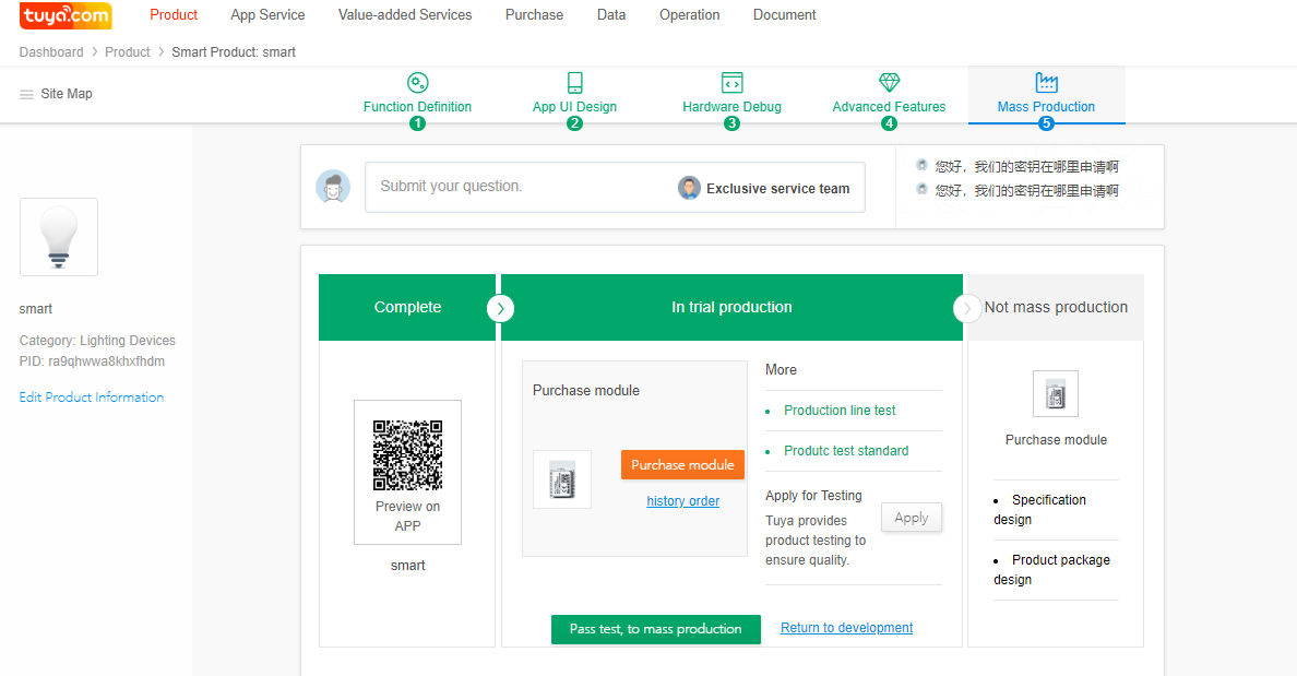
![SoC Development Overview](https://images.tuyacn.com/smart/announcement/1AELECTRICIAN_36.png)

Click **Purchase**. The **Purchase module** page is displayed. Click **Submit**, specify your receiving address and production and delivery requirements, and click **Submit the order**.Before mass production starts, click **apply** in the **In trial production** area to apply for product testing and send samples to the address on the page. The Tuya professional test team will test the product for you and provide you a professional test report. After your product passes the test, click **Pass test, to mass production**. After you release the product, you can click **Purchase module** to place a bulk order for the modules.

![SoC Development Overview](https://images.tuyacn.com/smart/announcement/1AELECTRICIAN_56.png)

![SoC Development Overview](https://images.tuyacn.com/smart/announcement/1AELECTRICIAN_57.png)

### Functions of the Development-free Solution <a href="#title-6-functions-20of-20the-20development-free-20solution" id="title-6-functions-20of-20the-20development-free-20solution"></a>

Tuya has provided SoC development-free solutions based on its extensive experience in successful product intelligence for tens of thousands of customers. Currently, the SoC solutions apply only to electrical engineering and lighting products. The following tables summarize functions of a development-free solution.<br>

![SoC Development Overview](https://images.tuyacn.com/smart/announcement/1AELECTRICIAN_69.png)

![SoC Development Overview](https://images.tuyacn.com/smart/announcement/1AELECTRICIAN_70.png)

Use the Tuya Smart or Smart Life App to scan the QR codes to experience some product solution functions.QR code for the development-free power statistics socket solution:

![](https://2999784448-files.gitbook.io/~/files/v0/b/gitbook-legacy-files/o/assets%2F-MBlD-pGvqUEQDs9SdgH%2F-MC2Eb-uVFmLFrPFSEuR%2F-MC2HHPStkBwohiFN7Nt%2Fimage.png?alt=media\&token=a1060905-be90-4157-bb41-3ef6df3d573d)

QR code for the development-free multi-way socket solution:

![](https://2999784448-files.gitbook.io/~/files/v0/b/gitbook-legacy-files/o/assets%2F-MBlD-pGvqUEQDs9SdgH%2F-MC2Eb-uVFmLFrPFSEuR%2F-MC2HVjW121LHp77sXZZ%2Fimage.png?alt=media\&token=34cee50f-5b7e-4251-abef-84ca84a67efe)

QR code for the development-free five-way bulb solution:

![](https://2999784448-files.gitbook.io/~/files/v0/b/gitbook-legacy-files/o/assets%2F-MBlD-pGvqUEQDs9SdgH%2F-MC2Eb-uVFmLFrPFSEuR%2F-MC2HZzhCjgs2IRO87qG%2Fimage.png?alt=media\&token=8854f2c8-091e-4da6-8b8a-fd7915a723f6)

### Development Process Using a SoC Custom Firmware Solution <a href="#title-7-development-20process-20using-20a-20soc-20custom-20firmware-20solution" id="title-7-development-20process-20using-20a-20soc-20custom-20firmware-20solution"></a>

#### Product Creation <a href="#title-8-product-20creation" id="title-8-product-20creation"></a>

**Logging In to the Tuya Smart Platform**

Log in to the Tuya Smart platform at <https://iot.tuya.com> with your Tuya account. If you do not have a Tuya account, register one.

#### Creating a Product <a href="#title-9-creating-20a-20product" id="title-9-creating-20a-20product"></a>

On the **Product** page, click **Create** in the **Easy Access to Get Your Smart Product** area.

![SoC Development Overview](https://images.tuyacn.com/smart/announcement/1AELECTRICIAN_2.png)

Click the product to be created under **Custom**.

![SoC Development Overview](https://images.tuyacn.com/smart/announcement/1AELECTRICIAN_58.png)

**Configuring Basic Product Information**

(Mandatory) Specify the product name. The product name is in *Brand* + *Product* + *Module model* format.

(Optional) Specify the product model (SN) to distinguish your product.

Select the correct communication mode for your product.

![SoC Development Overview](https://images.tuyacn.com/smart/announcement/1AELECTRICIAN_59.png)

#### Configuring the Product Online <a href="#title-10-configuring-20the-20product-20online" id="title-10-configuring-20the-20product-20online"></a>

Function Definition

Function Definition

![SoC Development Overview](https://images.tuyacn.com/smart/announcement/1AELECTRICIAN_60.png)

1. **Product configuration progress bar**: A product configuration progress bar is displayed on the top of the page. Configure the product information step by step.
2. **Submit your question**: Click **Submit your question** and report your development questions.
3. **Product information**: Thumbnail: indicates the type of the product that you have created.
4. **Common functions**: Select product functions.

Confirm the product information and functions, and click **Next**. You are advised to carefully confirm the selected functions to prevent rework.

**Function Customization**

Set and edit standard, custom, and cloud functions and click **Next**.

1. **Configure standard functions.**

Click **Setting** and add standard functions. Click **Edit** or **Delete** next to a single DP to edit or delete it.

![SoC Development Overview](https://images.tuyacn.com/smart/announcement/1AELECTRICIAN_61.png)

1. **Configure custom functions.**

![SoC Development Overview](https://images.tuyacn.com/smart/announcement/1AELECTRICIAN_62.png)

If standard functions do not meet your requirements, define custom functions. DPs are abstract representations of product functions, each of which can be defined by different functional types, including Boolean, numeric, enumeration, fault, string, and transparent.&#x20;

1. **Configure cloud functions.**

Timer and web page redirection are available. Tuya Cloud's timer function allows you to set the on/off time and intervals and does not require hardware development. The web page redirection function allows you to go to a web page from the App, for example, go to an online mall or the product user manual page.

![SoC Development Overview](https://images.tuyacn.com/smart/announcement/1AELECTRICIAN_63.png)

To display cloud functions on the App control panel, select a UI template that supports cloud functions on the **App UI Design** page. Only some UI templates support cloud functions. The following figure shows cloud functions displayed on the App control panel.

**App UI Design**

The **App UI Design** page of a SoC firmware custom solution is the same as that of a SoC development-free solution.

**Hardware Debug**

**Selecting a Module**

Click **Module details** to view detailed information about the selected module or click **Change module** to select another module. You are advised to select a recommended module that supports most product functions and can meet your product requirements.

![SoC Development Overview](https://images.tuyacn.com/smart/announcement/1AELECTRICIAN_64.png)

**Selecting a Development Solution**

Click **Use module custom firmware**, enter your contact method, specify your product requirements, and click **Submit Requirements**.

![SoC Development Overview](https://images.tuyacn.com/smart/announcement/1AELECTRICIAN_65.png)

The Tuya Smart professional team will evaluate your product requirements and selected solution, develop customized firmware, test the product, and mass-produce the product.

The **Advanced Features** and **Mass Production** settings for a SoC custom firmware custom solution are the similar to those for a SoC development-free solution.


# Lighting


# Guidance

Creating a Plug-and-Play RGBCW Lamp on the Tuya Smart Platform

### Preface <a href="#title-0-preface" id="title-0-preface"></a>

The Tuya Smart platform provides plug-and-play solutions with the Wi-Fi, BLE Mesh (SIG), Zigbee, and BLE Mesh (Tuya) communication modes for LED lighting products, including dimmable white lamps (C), CW or CCT lamps, RGB lamps, RGBC lamps, and RGBCW or RGBCCT lamps.

This document describes how to use a plug-and-play solution to develop a Wi-Fi RGBCW lamp on the Tuya Smart platform and the precautions.

### Registering with and Logging In to the Tuya Smart Platform <a href="#title-1-registering-20with-20and-20logging-20in-20to-20the-20tuya-20smart-20platform" id="title-1-registering-20with-20and-20logging-20in-20to-20the-20tuya-20smart-20platform"></a>
![Creating a Plug-and-Play RGBCW Lamp on the Tuya Smart Platform](https://images.tuyacn.com/smart/announcement/1A_2.png)

1. Register with and log in to the Tuya Smart platform at <https://iot.tuya.com>.
2. (Recommended) Complete enterprise certification to upgrade your account to a corporate account with more functions.
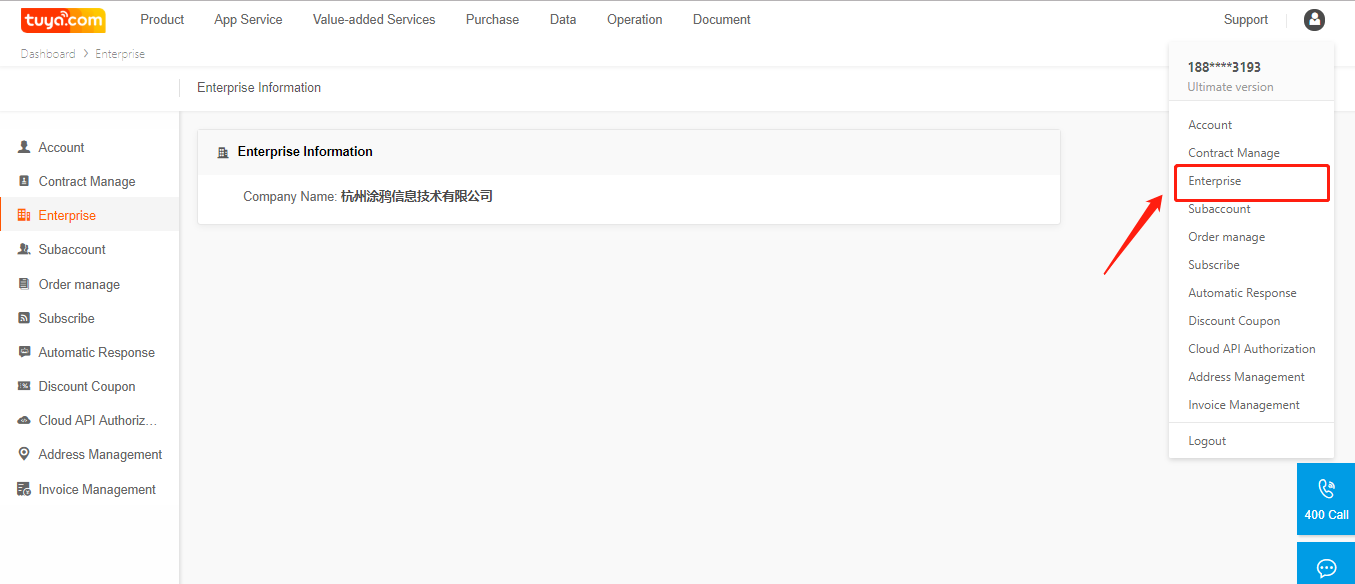
![Creating a Plug-and-Play RGBCW Lamp on the Tuya Smart Platform](https://images.tuyacn.com/smart/announcement/1AELECTRICIAN_1.png)

### Creating an SoC Plug-and-Play RGBCW Lamp <a href="#title-2-creating-20an-20soc-20plug-and-play-20rgbcw-20lamp" id="title-2-creating-20an-20soc-20plug-and-play-20rgbcw-20lamp"></a>

![Creating a Plug-and-Play RGBCW Lamp on the Tuya Smart Platform](https://images.tuyacn.com/smart/announcement/1AELECTRICIAN_2.png)

1. On the **Product** page, click **Create** in the **Easy Access to Get Your Smart Product** area.
2. (Recommended) On the displayed **Create new product** page, choose **Smart Lighting** and select a product under **Plug and Play Solution**. Alternatively, select a product under **Custom** if the development-free solution cannot meet your product function requirements.
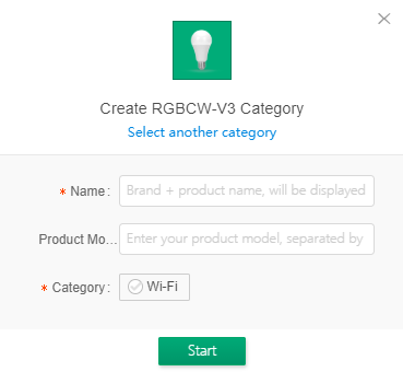
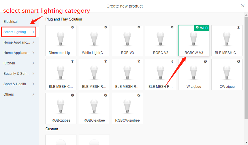
![Creating a Plug-and-Play RGBCW Lamp on the Tuya Smart Platform](https://images.tuyacn.com/smart/announcement/1AELECTRICIAN_25.png)![Creating a Plug-and-Play RGBCW Lamp on the Tuya Smart Platform](https://images.tuyacn.com/smart/announcement/1AELECTRICIAN_26.png)

1. Specify the product name, which will be displayed on the App control panel.
2. Specify the internal or customer product model to facilitate product maintenance and order management.
3. After the product is created, click **Edit Product Information** on the product configuration page to modify the product name and model.
4. If you subscribe to a third-party service for the product, the third-party service subscription icon is highlighted for the product on the **Product** page.![Creating a Plug-and-Play RGBCW Lamp on the Tuya Smart Platform](https://images.tuyacn.com/smart/announcement/1AELECTRICIAN_28.png)
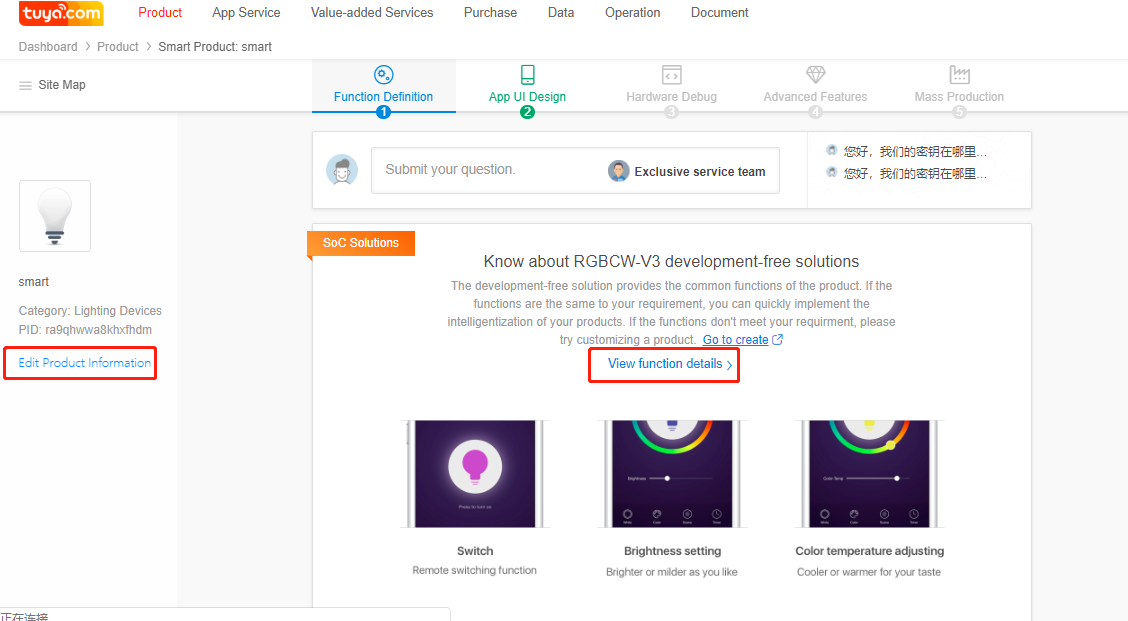
![Creating a Plug-and-Play RGBCW Lamp on the Tuya Smart Platform](https://images.tuyacn.com/smart/announcement/1AELECTRICIAN_29.png)

### Viewing DPs <a href="#title-3-viewing-20dps" id="title-3-viewing-20dps"></a>

You cannot modify data points (DPs) of a plug-and-play solution. To view the DPs, click **View function details**.

### Configuring the App Control Panel <a href="#title-4-configuring-20the-20app-20control-20panel" id="title-4-configuring-20the-20app-20control-20panel"></a>
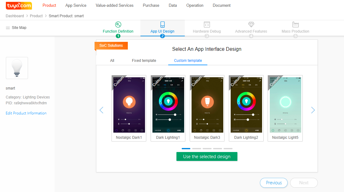
![Creating a Plug-and-Play RGBCW Lamp on the Tuya Smart Platform](https://images.tuyacn.com/smart/announcement/1AELECTRICIAN_27.png)

1. Click **App UI Design**. If you have upgraded your account to a corporate account, more templates and panel UI functions are available.
2. Select a control panel template and use the Tuya Smart or Smart Life App to scan the QR code to verify the control panel effect.
3. If you select a custom panel, click **Edit** to change panel elements, such as the background color and image.![Creating a Plug-and-Play RGBCW Lamp on the Tuya Smart Platform](https://images.tuyacn.com/smart/announcement/1AELECTRICIAN_30.png)
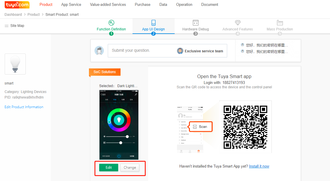
![Creating a Plug-and-Play RGBCW Lamp on the Tuya Smart Platform](https://images.tuyacn.com/smart/announcement/1AELECTRICIAN_31.png)

### Debugging the Hardware <a href="#title-5-debugging-20the-20hardware" id="title-5-debugging-20the-20hardware"></a>

Perform operations in this chapter to configure the module's electrical parameters. It is recommended that engineers perform these operations because setting the parameters requires professional knowledge.![Creating a Plug-and-Play RGBCW Lamp on the Tuya Smart Platform](https://images.tuyacn.com/smart/announcement/1AELECTRICIAN_32.png)
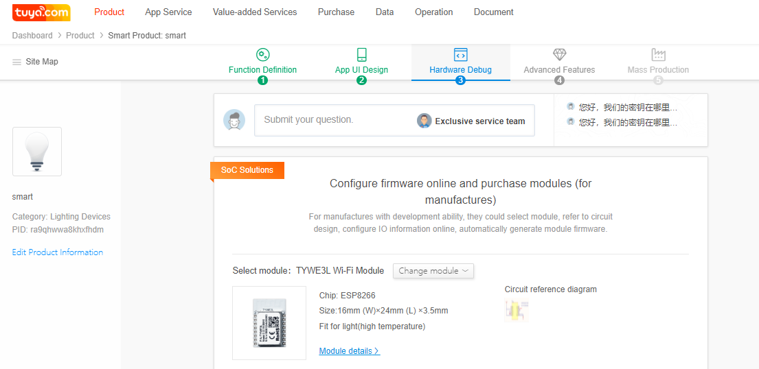
#### Selecting a Module and Checking the Reference Circuit Diagram (If you change the module, the reference circuit diagram will be updated.) <a href="#title-6-selecting-20a-20module-20and-20checking-20the-20reference-20circuit-20diagram-20-if-20you-20" id="title-6-selecting-20a-20module-20and-20checking-20the-20reference-20circuit-20diagram-20-if-20you-20"></a>

Select a module based on the product encapsulation, placement space, temperature, and antenna type. The Tuya Smart platform provides 10 Wi-Fi modules with their hardware design manuals and I/O interface connection diagrams. Note: The EN pins on the E3S and E3L modules need to be pulled up to a high level. Pay attention to the RF signal reference design. Modules recommended for different lighting products are as follows:

* Bulbs: TYE3L
* Filament lamps: TYLC5
* Candle lamps or GU10 bulbs: TYLC4
* Built-in power lamps or power lamps with metal covers: TYE1S-IPEX (supporting an external antenna)
* Power lamps with a plastic cover: TYE1S with an onboard antenna or TYE3S
* Compact products, such as light strip controllers: TYE2S

#### Configuring Module Firmware I/O Interface Information <a href="#title-7-configuring-20module-20firmware-20i-2fo-20interface-20information" id="title-7-configuring-20module-20firmware-20i-2fo-20interface-20information"></a>

**IIC Configuration**

![Creating a Plug-and-Play RGBCW Lamp on the Tuya Smart Platform](https://images.tuyacn.com/smart/aircondition/rgbcw1.png)

a) **IIC Data I/O Interface**: indicates the data I/O interface for IIC communication. Five I/O interfaces are available. If IIC communication is not required, select **None**. The first I/O interface is the default I/O interface.

b) **IIC Clock Signal I/O Interface**: indicates the clock signal I/O interface for IIC communication. Five I/O interfaces are available. If IIC communication is not required, select **None**. The first I/O interface is the default I/O interface.

c) **IIC-2135 Color Light Current**: indicates the RGB light current when the SM2135 chip that uses the IIC protocol is used. The value range is 10 mA to 45 mA.

d) **IIC-2135 White Light Current**: indicates the CW light current when the SM2135 chip that uses the IIC protocol is used. The value range is 10 mA to 60 mA.

e) **IIC-R**, **IIC-G**, **IIC-B**, **IIC-2135-W**, and **IIC-2135-C**: indicate pins on the SM2135 that control the red, green, blue, cold white, and warm white light when the SM2135 chip that uses the IIC protocol is used.

**Product Function**
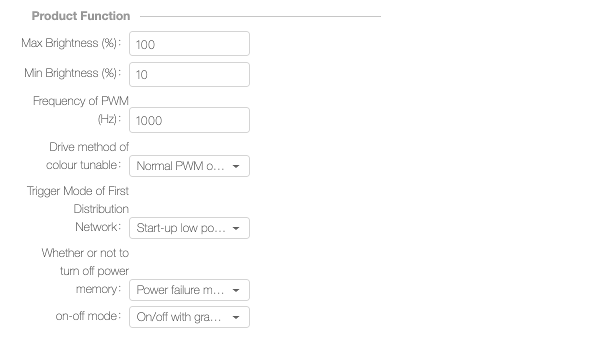
![Creating a Plug-and-Play RGBCW Lamp on the Tuya Smart Platform](https://images.tuyacn.com/smart/aircondition/rgbcw2.png)

a) **Max Brightness (%)** and **Min Brightness (%)**: indicate the maximum and minimum duty cycles of the PWM waveforms generated by the I/O interfaces for the cold and warm white light. The value range is 1 to 100.

Note: The **Min Brightness (%)** parameter must be set based on the dimming depth of the selected dimmable integrated circuit (IC). If they do not match, the lamp will turn off in low brightness. The default minimum brightness is 10%.

b) **PWM Frequency (Hz)**: indicates the frequency of each PWM control signal. The value range is 100 Hz to 20,000 Hz.

Note: The **PWM Frequency (Hz)** parameter must be set based on the PWM frequency that the dimmable IC supports. The frequency of most PWM ICs on the market is in the range of 500 Hz to 5000 Hz. When you adjust the frequency to 8000 Hz or higher, ripples in the light are invisible under the mobile phone camera.

c) **Color Temperature Drive Method**: Options are **CW-Cold/Warm** and **CCT-Brightness/Color Temperature**. The two methods have the same functions and UIs in the App and can control the color temperature and adjust the light brightness. They vary in the design of the peripheral circuit. For a CCT lamp, the two channels of PWM signals are independent of each other, with one controlling the overall current and the other adjusting the current proportions of the warm and cold light. Only one channel of PWM signals changes when you adjust the brightness or color. For a CW lamp, one channel of PWM signals controls the cold light while the other controls the warm light. Both channels of PWM signals change when you adjust the brightness or color. CW and CCT lamps are Tuya's internal classification methods. In the industry, CCT lamps are those with a color temperature adjustment feature, which are different from the CCT lamps in Tuya.

Note: This parameter is important. An incorrect value will cause incorrect light control logic. If you are not sure which value to select, send the schematic diagram to Tuya engineers for confirmation.

d) **Color Drive Pin Connection Method**: The options are **Normal PWM Output**, **CW-PWM+RGB-I2C(16726)**, and **CW- I2C(sm2135)+RGB-I2C(sm2135)**. **Normal PWM Output** indicates that three I/O interfaces generate PWM signals to control the red, green, and blue light. **CW-PWM+RGB-I2C(16726)** indicates that the IIC communication method controls the red, green, and blue light between the module and the SM726EB linear IC. **CW- I2C(sm2135)+RGB-I2C(sm2135)** indicates that the IIC communication method controls the red, green, and blue light between the module and the SM2135 linear IC. Note: If you select an incorrect method, the lamp cannot be controlled.

e) **First Network Configuration Trigger Mode**: indicates the method for the module to enter the network configuration mode. **Blink After Power Cycling** indicates that you power-cycle the module several times or press and hold the network configuration button for several seconds to enter the network configuration mode. **Blink After Power-on** indicates that the module automatically enters the network configuration mode after being powered on.

f) **Power-off Memory**: The options are **Power-off Memory** and **Restore to the Default State After Power Cycling**. **Power-off Memory** indicates that the module status remains unchanged each time the product is powered on. However, the status must be retained for over 5s before the product is powered off. **Restore to the Default State After Power Cycling** indicates that the white light is displayed with the default brightness and color temperature after the module enters the network configuration mode. For details on how to set the brightness and color temperature, see "(3) Network Configuration."

g) **On/Off Gradual Change**: indicates whether the module's PWM signal gradually changes from the current duty cycle to 0 when the product is powered off and gradually increases from 0 when being powered on. The options are **Yes** and **No**.

**Network Configuration**
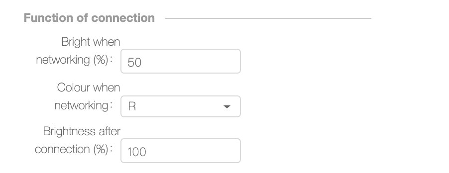
![Creating a Plug-and-Play RGBCW Lamp on the Tuya Smart Platform](https://images.tuyacn.com/smart/aircondition/rgbcw3.png)

a) **Brightness upon Network Configuration (%)**: indicates the blinking light brightness during network configuration. The value indicates the duty cycle of the PWM signal. The value range is 10 to 100. Note: The minimum dimming depth of some dimmable ICs is 10%. If **Brightness upon Network Configuration (%)** is set to **10**, the lamp will turn off during network configuration and will not blink. It is recommended that **Brightness upon Network Configuration (%)** be greater than 20.

b) **Color upon Network Configuration**: indicates the light blinks in network configuration mode. The options are **R**, **G**, **B**, **C**, and **W**.

c) **Brightness After Network Configuration (%)** and **Color Temperature After Network Configuration**: indicate the white light brightness and color temperature after network configuration. The values are the duty cycles of the PWM signals for controlling the white light brightness and color temperature. Note: The brightness value must be greater than the minimum dimming depth of the dimmable IC, or the lamp will turn off after network configuration. Consumers may think that the lamp is faulty.

**I/O Settings**
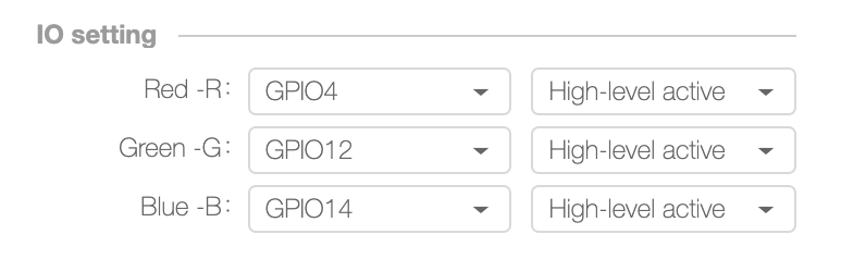
![Creating a Plug-and-Play RGBCW Lamp on the Tuya Smart Platform](https://images.tuyacn.com/smart/aircondition/rgbcw4.png)

Select the I/O interfaces and levels for the red, green, blue, cold white (bright), and warm white (CCT) control signals.

**Network Configuration Settings**
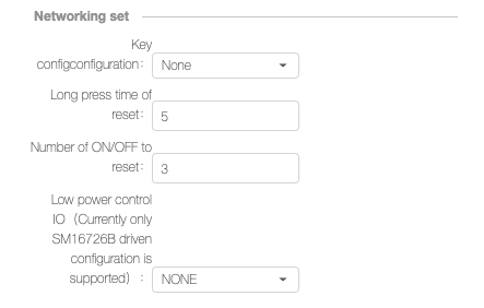
![Creating a Plug-and-Play RGBCW Lamp on the Tuya Smart Platform](https://images.tuyacn.com/smart/aircondition/rgbcw5.png)

a) **Network Configuration Button**: indicates whether you can press and hold a button to enter the network configuration mode. The options are **None** and multiple I/O interfaces. The value **None** indicates that you cannot press and hold a button to enter the network configuration mode. If an I/O interface is selected, you can press and hold this button to enter the network configuration mode. Note: Select **None** if you do not need to press and hold the network configuration button to enter the network configuration mode. If an I/O interface is selected but not used, the module may be powered on or off unexpectedly.

b) **Button Pressing Time (s)**: indicates the time for pressing and holding the button to enter the network configuration mode. The value range is from 3s to 10s. If **Network Configuration Button** is set to **None**, this parameter does not need to be specified.

c) **Number of Resets**: indicates the number of resets for the module firmware to enter the network configuration mode. The value range is 3 to 10. Note: To power cycle the module's Vcc pin, power cycle the lamp. During network configuration, ensure that the voltage of the Vcc pin is Approaching 0 V before you power the lamp on.

d) **Low-power Control Pin**: indicates the low-power pin during IIC control. Currently, the pin can be configured only under the SM16726B drive. That is, this parameter needs to be specified only if **Color Drive Pin Connection Method** is set to **CW-PWM+RGB-I2C(16726)**.

Note: After all the parameters are configured, click **Save** on the top of the page for the parameters to take effect.

#### Purchasing Modules <a href="#title-8-purchasing-20modules" id="title-8-purchasing-20modules"></a>

After completing the configuration, click **Purchase** to purchase a small number of the modules for product debugging.

**Note: The module will be burned based on the settings that you specify on this page. After the module is delivered, the settings cannot be modified. To modify the settings, repurchase a module. If you modify the settings after the module is delivered, any online upgrades will not apply to the product because the settings will be inconsistent.**

### Configuring Advanced Features <a href="#title-9-configuring-20advanced-20features" id="title-9-configuring-20advanced-20features"></a>

For details on how to configure advanced features, visit <https://docs.tuya.com/en/soc/soc-dev.html>.

### Mass Production <a href="#title-10-mass-20production" id="title-10-mass-20production"></a>

![Creating a Plug-and-Play RGBCW Lamp on the Tuya Smart Platform](https://images.tuyacn.com/smart/announcement/1AELECTRICIAN_35.png)

1. After you receive the sample modules and complete product debugging, send at least two product samples to Tuya for testing and verifying the product status.
2. After the sample product passes the test, click **Complete development** to enter the trial production phase.
3. After trial production is completed, click **Pass test, to mass production**. In the mass production phase, product settings cannot be modified to prevent misoperations and impact on consumers.
4. Do not delete products that are under development or have been developed to prevent data loss and causing the product to fail to function properly.![Creating a Plug-and-Play RGBCW Lamp on the Tuya Smart Platform](https://images.tuyacn.com/smart/announcement/1AELECTRICIAN_36.png)


# Design

Step-by-Step Tuya Smart Lighting Product Design

### Step 1: Select a Module <a href="#title-0-step-201-3a-20select-20a-20module" id="title-0-step-201-3a-20select-20a-20module"></a>

#### Wi-Fi Modules   <a href="#title-1-wi-fi-20modules" id="title-1-wi-fi-20modules"></a>

![Step-by-Step Tuya Smart Lighting Product Design](https://images.tuyacn.com/smart/aircondition/light-design73.png)

![Step-by-Step Tuya Smart Lighting Product Design](https://images.tuyacn.com/smart/aircondition/light-design72.png)

![Step-by-Step Tuya Smart Lighting Product Design](https://images.tuyacn.com/smart/aircondition/light-design71.png)

![Step-by-Step Tuya Smart Lighting Product Design](https://images.tuyacn.com/smart/aircondition/light-design70.png)

![Step-by-Step Tuya Smart Lighting Product Design](https://images.tuyacn.com/smart/aircondition/light-design69.png)

#### Bluetooth mesh Modules (Tuya) <a href="#title-2-bluetooth-20mesh-20modules-20-tuya" id="title-2-bluetooth-20mesh-20modules-20-tuya"></a>

![](https://2999784448-files.gitbook.io/~/files/v0/b/gitbook-legacy-files/o/assets%2F-MBlD-pGvqUEQDs9SdgH%2F-MC2IL4DWNRrbz1q8D5w%2F-MC2K0ghbABuWfEwYvWI%2Fimage.png?alt=media\&token=6eb08227-6d32-4e1b-aafa-d223693d40bc)

#### Bluetooth mesh Modules (SIG) <a href="#title-3-bluetooth-20mesh-20modules-20-sig" id="title-3-bluetooth-20mesh-20modules-20-sig"></a>

![](https://2999784448-files.gitbook.io/~/files/v0/b/gitbook-legacy-files/o/assets%2F-MBlD-pGvqUEQDs9SdgH%2F-MC2IL4DWNRrbz1q8D5w%2F-MC2K4wDjuzATQKQABwf%2Fimage.png?alt=media\&token=04c2b271-807a-49f5-9bfd-b55f992e096a)

#### Zigbee Modules <a href="#title-4-zigbee-20modules" id="title-4-zigbee-20modules"></a>

![](https://2999784448-files.gitbook.io/~/files/v0/b/gitbook-legacy-files/o/assets%2F-MBlD-pGvqUEQDs9SdgH%2F-MC2IL4DWNRrbz1q8D5w%2F-MC2K8MWwEv9E50Yb7S1%2Fimage.png?alt=media\&token=5022d14b-f72d-4934-aadd-9e2b624376cd)

### Step 2: Select a Module Power Supply Mode <a href="#title-5-step-202-3a-20select-20a-20module-20power-20supply-20mode" id="title-5-step-202-3a-20select-20a-20module-20power-20supply-20mode"></a>

#### AC-DC Constant-Voltage Power Supply <a href="#title-6-ac-dc-20constant-voltage-20power-20supply" id="title-6-ac-dc-20constant-voltage-20power-20supply"></a>

* A module's normal working voltage range is 3.0 V to 3.6 V.
* If the output voltage is higher than 3.3 V, consider the output voltage ripple and output power in addition to the power to the module to prevent insufficient power supply to the module due to undervoltage output. The power supply system must ensure a stable power supply voltage under the maximum output power.
* If the output voltage is the module's power supply voltage or 3.3 V, set the output voltage central value to 3.3 V to have a ripple voltage of less than 100 mV and an average Wi-Fi module current of about 80 mA. The AC-DC power supply system must generate 200 mA current on average. The peak value of the dynamic output current of the power supply system must reach 450 mA, and the voltage drop cannot exceed 2.8 V. The 3.3 V Wi-Fi module's power supply pin is connected to a 0.1 μF ceramic capacitor to reduce interference. To power a 3.3 V Bluetooth or Zigbee module, the AC-DC power supply system must have a ripple voltage of less than 100 mV and can generate 50 mA current on average. When the dynamic output current is 100 mA, the output voltage drop does not exceed 2.8 V.
* In low standby power application scenarios, select the low standby power AC-DC drive chip and a module with low standby current.
* Use a diode and capacitor to isolate the AC-DC power supply circuit from the main power (highlighted with the red rectangle in the following figure) to prevent the working module from affecting the main power, especially the linear constant-current drive power source, so that light jitter will not occur.
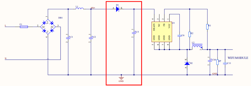
![Step-by-Step Tuya Smart Lighting Product Design](https://images.tuyacn.com/smart/aircondition/light-degisn1.png)

#### DC-DC Constant-Voltage Power Supply <a href="#title-7-dc-dc-20constant-voltage-20power-20supply" id="title-7-dc-dc-20constant-voltage-20power-20supply"></a>

* When a module embedded with a DC-DC voltage reduction circuit is powered by DC voltage, the DC voltage cannot exceed 40 V.
* When the DC voltage exceeds 3.3 V, use a voltage reduction chip to reduce the voltage to 3.3 V. A switch-type voltage reduction control chip is recommended, as shown in the following figure. To power a 3.3 V Wi-Fi module, the DC-DC power supply system must have a ripple voltage of less than 100 mV and can generate 200 mA current. When the dynamic output current is 450 mA, the output voltage drop does not exceed 2.8 V. The 3.3 V Wi-Fi module's power supply pin is connected to a 0.1 μF ceramic capacitor to reduce interference. To power a 3.3 V Bluetooth or Zigbee module, the DC-DC power supply system must have a ripple voltage of less than 100 mV and can generate 50 mA current on average. When the dynamic output current is 100 mA, the output voltage drop does not exceed 2.8 V.

![](https://2999784448-files.gitbook.io/~/files/v0/b/gitbook-legacy-files/o/assets%2F-MBlD-pGvqUEQDs9SdgH%2F-MC2IL4DWNRrbz1q8D5w%2F-MC2Kd1v9G_wOGZNRkKw%2Fimage.png?alt=media\&token=8031212f-ff3c-4111-816c-d0e5e57c9963)

\* Low dropout (LDO) regulators are not recommended for powering Wi-Fi modules. If an LDO regulator is used, use a chip with 500 mA or higher power supply current and ensure good heat dissipation. When the input voltage is higher than 5 V, a switch-type power chip is recommended.

### Step 3: Install the Module and Antenna <a href="#title-8-step-203-3a-20install-20the-20module-20and-20antenna" id="title-8-step-203-3a-20install-20the-20module-20and-20antenna"></a>

Similar to light, wireless signals may be blocked by metal in the transmission path. If an antenna is mounted on a metal surface, the module cannot work properly.

To use a module in a sphere lamp, ensure that the module's antenna is out of the opening groove of the alumina substrate and that the onboard antenna is higher than the alumina substrate. When the light source is not affected and there are no shadows, position the antenna out of the lamp cup's shielding environment as much as possible.

When using a module in a lamp with a metal cover, for example, a downlight or spotlight lamp or lamp used outdoors, consider the antenna RF design and use an external antenna if needed. To use a module in a drive, keep the module away from components such as the transformer and inductor.

### Step 4: Select an LED Light Driving Method <a href="#title-9-step-204-3a-20select-20an-20led-20light-20driving-20method" id="title-9-step-204-3a-20select-20an-20led-20light-20driving-20method"></a>

#### AC-DC Constant-Current Driver for Monochromatic Lamps (W) <a href="#title-10-ac-dc-20constant-current-20driver-20for-20monochromatic-20lamps-20-w" id="title-10-ac-dc-20constant-current-20driver-20for-20monochromatic-20lamps-20-w"></a>

* Switch-type AC-DC constant-current driver, as shown in the following figure

Advantages: high efficiency, high power factor (PF), good constant-current characteristics, high linearity, and adjustable, wide output voltage range

Disadvantages: strong electromagnetic interference (EMI), high cost, noise during PWM light adjustment, and complex PCB layout

The module generates PWM signals.
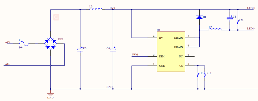
![Step-by-Step Tuya Smart Lighting Product Design](https://images.tuyacn.com/smart/aircondition/light-design4.png)

\* Linear AC-DC constant-current driver

Advantages: low cost, no EMI issue, simple PCB layout, and no noise during PWM light adjustment

Disadvantages: low efficiency, narrow voltage range, poor constant-current characteristics, poor linearity, fixed output voltage, and low PF

The module generates PWM signals.
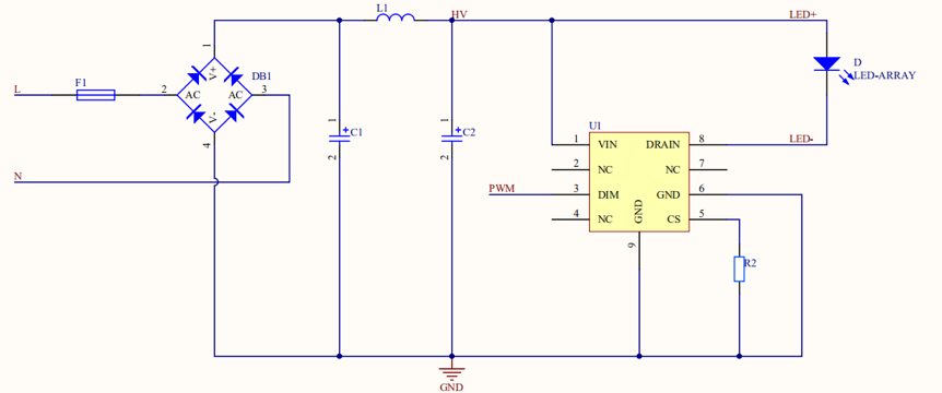
![Step-by-Step Tuya Smart Lighting Product Design](https://images.tuyacn.com/smart/aircondition/light-design5.png)

#### AC-DC Constant-Current Driver for Bi-Color Lamps (CW) <a href="#title-11-ac-dc-20constant-current-20driver-20for-20bi-color-20lamps-20-cw" id="title-11-ac-dc-20constant-current-20driver-20for-20bi-color-20lamps-20-cw"></a>

The solution has the CW and CCT control modes. The CW mode uses 2-channel PWM signals for simultaneous control of the brightness and color temperature. The 2-channel PWM signals are CW and WW signals, which respectively control the white light with a high color temperature and warm light with a low color temperature. During 1-channel light adjustment, CW signals are used. The CCT mode uses 2-channel PWM signals for separate control of the brightness and color temperature. The Bright signals control the brightness, and the CCT signals control the color temperature. For details, see the pin configuration.

* Switch-type AC/DC constant-current driver in CW mode

Advantages: high efficiency, good constant-current characteristics, high linearity, and good light adjustment

Disadvantages: strong EMI, circuit noise, large color temperature offset when the duty cycle is small, complex circuit layout, and high cost

The module generates 2-channel PWM signals: CW and WW.

![](https://2999784448-files.gitbook.io/~/files/v0/b/gitbook-legacy-files/o/assets%2F-MBlD-pGvqUEQDs9SdgH%2F-MC2IL4DWNRrbz1q8D5w%2F-MC2L9DXRIoAvIr2AIEc%2Fimage.png?alt=media\&token=568a6192-9975-49ed-bc6c-95872a002f70)

\* Linear AC-DC constant-current driver in CW mode

Advantages: low cost, no EMI issue, simple PCB layout, and no noise during PWM light adjustment

Disadvantages: low efficiency, narrow voltage range, poor constant-current characteristics, poor linearity, fixed output voltage, and large color temperature offset when the duty cycle is small

The module generates 2-channel PWM signals: CW and WW.
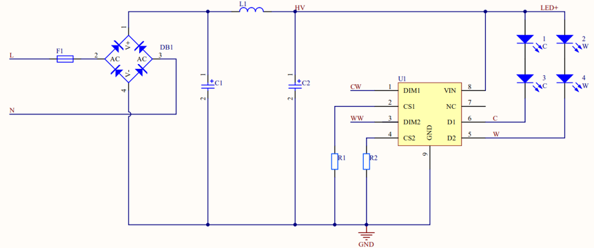
![Step-by-Step Tuya Smart Lighting Product Design](https://images.tuyacn.com/smart/aircondition/light-design7.png)

* AC-DC constant-current driver in CCT mode

Advantages: high efficiency, good constant-current characteristics, high linearity, basically no color temperature offset, good light adjustment, simulated brightness control, low cost, simple circuit layout, and no noise

Disadvantages: strong EMI and higher cost than the linear AC-DC constant-current driver in CW mode

The module generates 2-channel PWM signals: Bright and CCT.
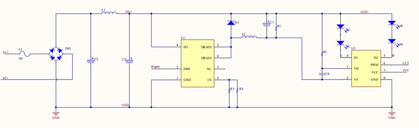
![Step-by-Step Tuya Smart Lighting Product Design](https://images.tuyacn.com/smart/aircondition/light-design8.png)

#### Constant-Current Driver for RGB Lamps <a href="#title-12-constant-current-20driver-20for-20rgb-20lamps" id="title-12-constant-current-20driver-20for-20rgb-20lamps"></a>

* DC-DC PWM-controlled linear constant-current driver

The module generates 3-channel PWM signals: PWMR, PWMG, and PWMB. The linear constant-current driver ensures constant RGB current output.
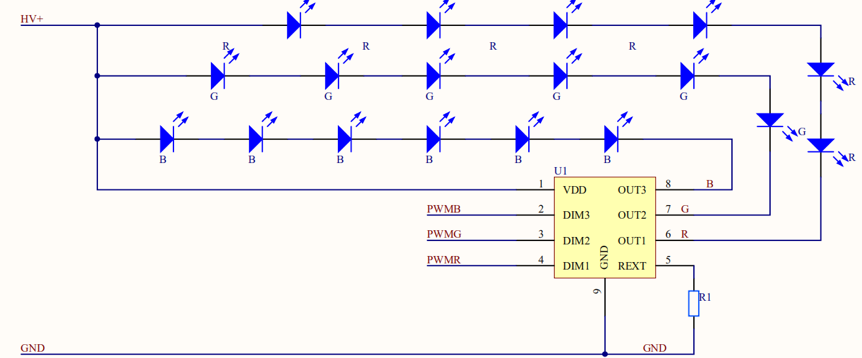
![Step-by-Step Tuya Smart Lighting Product Design](https://images.tuyacn.com/smart/aircondition/light-design9.png)

* DC-DC I2C-controlled linear constant-current driver

The I2C DAT and CLK signals can control RGB or RGBCW lamps, requiring only several control pins. The module generates I2C DAT and CLK signals to the drive chip to ensure constant RGB current. To use the I2C solution, pay attention to the PCB layout. I2C signals are vulnerable to interference from switch signals (AC-DC drive circuit). If the interference is serious, add a 10 pF to 50 pF filter capacitor to the DAT and CLK signal circuits during PCB layout design to reduce interference.
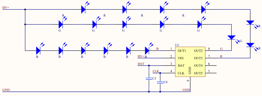
![Step-by-Step Tuya Smart Lighting Product Design](https://images.tuyacn.com/smart/aircondition/light-design10.png)

Note: Pull-up resistors need to be added to the physical circuits of the peripheral I2C DAT and CLK signals. Typically, the resistance value is 4.7 kiloohms, which can be adjusted based on the actual scenario.
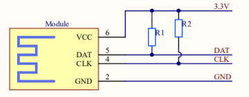
![Step-by-Step Tuya Smart Lighting Product Design](https://images.tuyacn.com/smart/aircondition/light-design11.png)

* DC-DC PWM-controlled BJT/MOSFET switch driver

Use the BJT or MOSFET switch to control RGB through PWM signals. The RGB current is variable and discrete. Add a resistor for the red light control channel to limit the current because the red light diode has a low voltage. In this case, under the same input conditions as the constant-current solution, the loss is increased. Note: The bead voltage cannot be greatly different from the input voltage.
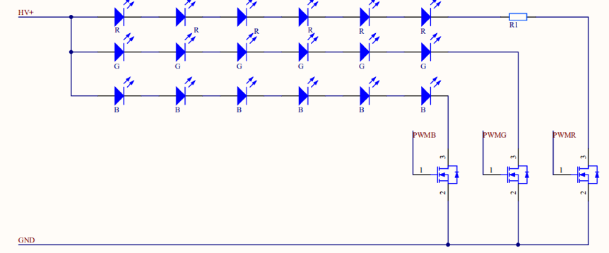
![Step-by-Step Tuya Smart Lighting Product Design](https://images.tuyacn.com/smart/aircondition/light-design12.png)

#### AC-DC I2C-controlled Linear Constant-Current Driver for RGBCW Lamps <a href="#title-13-ac-dc-20i2c-controlled-20linear-20constant-current-20driver-20for-20rgbcw-20lamps" id="title-13-ac-dc-20i2c-controlled-20linear-20constant-current-20driver-20for-20rgbcw-20lamps"></a>

Advantages: simple solution, simple peripheral parameters, low cost, and requires only the DAT and CLK signals for control

Disadvantages: driven by linear constant current, and DAT and CLK signals are vulnerable to interference

Note: The RGB light needs to be powered separately. An AC-DC + DC-DC power supply solution is recommended.
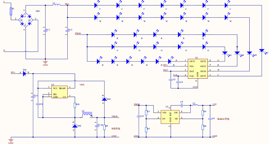
![Step-by-Step Tuya Smart Lighting Product Design](https://images.tuyacn.com/smart/aircondition/light-design13.png)

### Step 5: Define Module Pins <a href="#title-14-step-205-3a-20define-20module-20pins" id="title-14-step-205-3a-20define-20module-20pins"></a>

In network configuration mode, the CW pin generates a high or low level to indicate the network configuration status. The CW pin is used for 1-channel light control. For cold and warm light control in CW mode, the CW and WW pins control the cold and warm light, respectively. In CCT control mode, the Bright and CCT pins respectively control the brightness and color temperature.

The following tables define the module pins.

#### WIFI： <a href="#title-15-wifi-ef-bc-9a" id="title-15-wifi-ef-bc-9a"></a>

**Espressif Systems:**

**TYWE3S TYWE3L TYWE5P**

| I/O Interface | W  | CW  | CCT    | RGB(PWM)  | RGB (I2C) |
| ------------- | -- | --- | ------ | --------- | --------- |
| IO5           | W  | CW  | Bright |           |           |
| IO13          | WW | CCT |        |           |           |
| IO4           |    |     | R      | SCL       |           |
| IO12          |    |     | G      |           |           |
| IO14          |    |     | B      | SDA       |           |
| IO16          |    |     |        | Low-power |           |

**TYWE3SE**

| I/O Interface | W  | CW  | CCT    | RGB(PWM)  | RGB (I2C) |
| ------------- | -- | --- | ------ | --------- | --------- |
| IO22          | W  | CW  | Bright |           |           |
| IO13          | WW | CCT |        |           |           |
| IO5           |    |     | R      | SCL       |           |
| IO25          |    |     | G      |           |           |
| IO14          |    |     | B      | SDA       |           |
| IO33          |    |     |        | Low-power |           |

**TYWE1S TYLC4**

| I/O Interface | W  | CW  | CCT    | RGB(PWM)  | RGB (I2C) |
| ------------- | -- | --- | ------ | --------- | --------- |
| IO5           | W  | CW  | Bright |           |           |
| IO13          | WW | CCT |        |           |           |
| IO4           |    |     | R      | SCL       |           |
| IO12          |    |     | G      | Low-power |           |
| IO14          |    |     | B      | SDA       |           |

**TYWE2S TYWE2L**

| I/O Interface | W  | CW  | CCT    | RGB(PWM)  | RGB (I2C) |
| ------------- | -- | --- | ------ | --------- | --------- |
| IO14          | W  | CW  | Bright |           |           |
| IO12          | WW | CCT |        |           |           |
| IO5           |    |     | R      | SCL       |           |
| IO4           |    |     | G      | Low-power |           |
| IO13          |    |     | B      | SDA       |           |

**TYLC5**

| I/O Interface | W  | CW  | CCT    | RGB(PWM)  | RGB (I2C) |
| ------------- | -- | --- | ------ | --------- | --------- |
| IO14          | W  | CW  | Bright | R         | SCL       |
| IO12          | WW | CCT | B      | SDA       |           |
| IO4           |    |     | G      | Low-power |           |

**TYLC6 TYLC8**

| I/O Interface | W  | CW  | CCT    | RGB(PWM)  | RGB (I2C) |
| ------------- | -- | --- | ------ | --------- | --------- |
| IO14          | W  | CW  | Bright | R         | SCL       |
| IO12          | WW | CCT | B      | SDA       |           |
| IO13          |    |     | G      | Low-power |           |

**TYLC6E**

| I/O Interface | W  | CW  | CCT    | RGB(PWM)  | RGB (I2C) |
| ------------- | -- | --- | ------ | --------- | --------- |
| IO4           | W  | CW  | Bright |           |           |
| IO5           | WW | CCT | R      |           |           |
| IO12          |    |     | G      | SDA       |           |
| IO14          |    |     | B      | SCL       |           |
| IO13          |    |     |        | Low-power |           |

**TYLC2V**

| I/O Interface | W  | CW  | CCT    | RGB(PWM)  | RGB (I2C) |
| ------------- | -- | --- | ------ | --------- | --------- |
| IO5           | W  | CW  | Bright |           |           |
| IO12          | WW | CCT | R      |           |           |
| IO14          |    |     | G      | SDA       |           |
| IO4           |    |     | B      | SCL       |           |
| IO13          |    |     |        | Low-power |           |

**Realtek module pins:**

**WR1 (Pin-compatible with TYWE1S)**

| I/O Interface | W  | CW  | CCT    | RGB(PWM)  | RGB (I2C) |
| ------------- | -- | --- | ------ | --------- | --------- |
| GPIOA\_5      | W  | CW  | Bright |           |           |
| GPIOA\_18     | WW | CCT |        |           |           |
| GPIOA\_22     |    |     | R      | SCL       |           |
| GPIOA\_15     |    |     | G      | Low-power |           |
| GPIOA\_14     |    |     | B      | SDA       |           |

**WR3 and WR3L (Pin-compatible with TYWE3S and TYWE3L)**

| I/O Interface | W  | CW  | CCT    | RGB(PWM)  | RGB (I2C) |
| ------------- | -- | --- | ------ | --------- | --------- |
| GPIOA\_12     | W  | CW  | Bright |           |           |
| GPIOA\_0      | WW | CCT |        |           |           |
| GPIOA\_5      |    |     | R      | SCL       |           |
| GPIOA\_15     |    |     | G      |           |           |
| GPIOA\_14     |    |     | B      | SDA       |           |
| GPIOA\_19     |    |     |        | Low-power |           |

**WR3E and WR3LE (Pin-compatible with TYWE3S and TYWE3L)**

| I/O Interface | W  | CW  | CCT    | RGB(PWM)  | RGB (I2C) |
| ------------- | -- | --- | ------ | --------- | --------- |
| GPIOA\_12     | W  | CW  | Bright |           |           |
| GPIOA\_22     | WW | CCT |        |           |           |
| GPIOA\_5      |    |     | R      | SCL       |           |
| GPIOA\_15     |    |     | G      |           |           |
| GPIOA\_14     |    |     | B      | SDA       |           |
| GPIOA\_29     |    |     |        | Low-power |           |

**WR5P (Pin-compatible with TYWE5P)**

| I/O Interface | W  | CW  | CCT    | RGB(PWM)  | RGB (I2C) |
| ------------- | -- | --- | ------ | --------- | --------- |
| GPIOA\_12     | W  | CW  | Bright |           |           |
| GPIOA\_5      | WW | CCT |        |           |           |
| GPIOA\_14     |    |     | R      | SCL       |           |
| GPIOA\_15     |    |     | G      |           |           |
| GPIOA\_0      |    |     | B      | SDA       |           |
| GPIOA\_22     |    |     |        | Low-power |           |

**RLC2V and RLC7V (Pin-compatible with TYLC2V)**

| I/O Interface | W  | CW  | CCT    | RGB(PWM)  | RGB (I2C) |
| ------------- | -- | --- | ------ | --------- | --------- |
| GPIOA\_5      | W  | CW  | Bright |           |           |
| GPIOA\_12     | WW | CCT | R      |           |           |
| GPIOA\_14     |    |     | G      | SDA       |           |
| GPIOA\_15     |    |     | B      | SCL       |           |
| GPIOA\_0      |    |     |        | Low-power |           |

**RLC4 (Pin-compatible with TYLC4)**

| I/O Interface | W  | CW  | CCT    | RGB(PWM)  | RGB (I2C) |
| ------------- | -- | --- | ------ | --------- | --------- |
| GPIOA\_5      | W  | CW  | Bright |           |           |
| GPIOA\_12     | WW | CCT |        |           |           |
| GPIOA\_19     |    |     | R      | SCL       |           |
| GPIOA\_15     |    |     | G      | Low-power |           |
| GPIOA\_14     |    |     | B      | SDA       |           |

**WR2L (Pin-compatible with TYWE2L)**

| I/O Interface | W  | CW  | CCT    | RGB(PWM)  | RGB (I2C) |
| ------------- | -- | --- | ------ | --------- | --------- |
| GPIOA\_15     | W  | CW  | Bright |           |           |
| GPIOA\_14     | WW | CCT |        |           |           |
| GPIOA\_19     |    |     | R      | SCL       |           |
| GPIOA\_12     |    |     | G      | Low-power |           |
| GPIOA\_5      |    |     | B      | SDA       |           |

**WR2E (Pin-compatible with TYWE2S)**

| I/O Interface | W  | CW  | CCT    | RGB(PWM)  | RGB (I2C) |
| ------------- | -- | --- | ------ | --------- | --------- |
| GPIOA\_15     | W  | CW  | Bright |           |           |
| GPIOA\_24     | WW | CCT |        |           |           |
| GPIOA\_12     |    |     | R      | SCL       |           |
| GPIOA\_19     |    |     | G      | Low-power |           |
| GPIOA\_5      |    |     | B      | SDA       |           |

**WR2 (Pin-compatible with TYWE2S)**

| I/O Interface | W  | CW  | CCT    | RGB(PWM)  | RGB (I2C) |
| ------------- | -- | --- | ------ | --------- | --------- |
| GPIOA\_15     | W  | CW  | Bright |           |           |
| GPIOA\_14     | WW | CCT |        |           |           |
| GPIOA\_12     |    |     | R      | SCL       |           |
| GPIOA\_0      |    |     | G      | Low-power |           |
| GPIOA\_5      |    |     | B      | SDA       |           |

#### Tuya Bluetooth mesh module pins: <a href="#title-16-tuya-20bluetooth-20mesh-20module-20pins-3a" id="title-16-tuya-20bluetooth-20mesh-20module-20pins-3a"></a>

**TYBY3**

| I/O Interface | W  | CW  | CCT    | RGB(PWM)  | RGB (I2C) |
| ------------- | -- | --- | ------ | --------- | --------- |
| GPIOA\_15     | W  | CW  | Bright |           |           |
| GPIOA\_14     | WW | CCT |        |           |           |
| GPIOA\_12     |    |     | R      | SCL       |           |
| GPIOA\_0      |    |     | G      | Low-power |           |
| GPIOA\_5      |    |     | B      | SDA       |           |

**TYBT4L (Pin-compatible with TYWE3S)**

| I/O Interface | W  | CW  | CCT    | RGB(PWM)  | RGB (I2C) |
| ------------- | -- | --- | ------ | --------- | --------- |
| GPIOA\_15     | W  | CW  | Bright |           |           |
| GPIOA\_14     | WW | CCT |        |           |           |
| GPIOA\_12     |    |     | R      | SCL       |           |
| GPIOA\_0      |    |     | G      |           |           |
| GPIOA\_5      |    |     | B      | SDA       |           |
| GPIOA\_5      |    |     |        | Low-power |           |

**TYBT8 (Pin-compatible with TYLC5)**

| I/O Interface | W  | CW  | CCT    | RGB(PWM)  | RGB (I2C) |
| ------------- | -- | --- | ------ | --------- | --------- |
| PWM1          | W  | CW  | Bright | R         | SCL       |
| PWM0          | WW | CCT | B      | SDA       |           |
| PWM4          |    |     | G      | Low-power |           |

#### SIG Bluetooth mesh module pins: <a href="#title-17-sig-20bluetooth-20mesh-20module-20pins-3a" id="title-17-sig-20bluetooth-20mesh-20module-20pins-3a"></a>

**BT3L (Pin-compatible with TYWE3S)**

| I/O Interface | W  | CW  | CCT    | RGB(PWM)  | RGB (I2C) |
| ------------- | -- | --- | ------ | --------- | --------- |
| TL\_B5        | W  | CW  | Bright |           |           |
| TL\_C2        | WW | CCT |        |           |           |
| TL\_B4        |    |     | R      | SCL       |           |
| TL\_C3        |    |     | G      |           |           |
| TL\_D2        |    |     | B      | SDA       |           |
| TL-D7         |    |     |        | Low-power |           |

**BT8C (Pin-compatible with TYLC5 and TYBT8)**

| I/O Interface | W  | CW  | CCT    | RGB(PWM)  | RGB (I2C) |
| ------------- | -- | --- | ------ | --------- | --------- |
| PWM1          | W  | CW  | Bright | R         | SCL       |
| PWM0          | WW | CCT | B      | SDA       |           |
| PWM4          |    |     | G      | Low-power |           |

#### Zigbee module pins <a href="#title-18-zigbee-20module-20pins" id="title-18-zigbee-20module-20pins"></a>

**TYZS3 and TYZS1L (Pin-compatible with TYWE3S)**

| I/O Interface | W  | CW  | CCT    | RGB(PWM)  | RGB (I2C) |
| ------------- | -- | --- | ------ | --------- | --------- |
| GPIO3         | W  | CW  | Bright |           |           |
| PWM1          | WW | CCT |        |           |           |
| PWM2          |    |     | R      | SCL       |           |
| PWM3          |    |     | G      |           |           |
| SWO           |    |     | B      | SDA       |           |
| GPIO0         |    |     |        | Low-power |           |

**TYZS15 (Pin-compatible with TYLC5, TYBT8, and BT8C)**

| I/O Interface | W  | CW  | CCT    | RGB(PWM)  | RGB (I2C) |
| ------------- | -- | --- | ------ | --------- | --------- |
| PWM3          | W  | CW  | Bright | R         | SCL       |
| PWM1          | WW | CCT | B      | SDA       |           |
| PWM2          |    |     | G      | Low-power |           |

**TYZS9V (Pin-compatible with TYLC2V)**

| I/O Interface | W  | CW  | CCT    | RGB(PWM)  | RGB (I2C) |
| ------------- | -- | --- | ------ | --------- | --------- |
| PWM2          | W  | CW  | Bright |           |           |
| GPIO2         | WW | CCT | R      |           |           |
| PWM3          |    |     | G      | SDA       |           |
| PWM1          |    |     | B      | SCL       |           |
| GPIO0         |    |     |        | Low-power |           |

**The following figures show pins on some modules:**
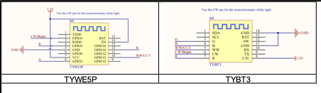
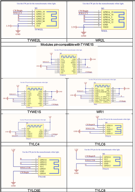
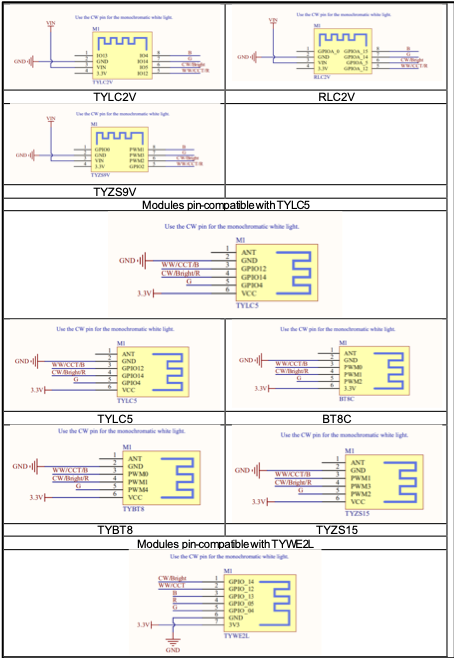
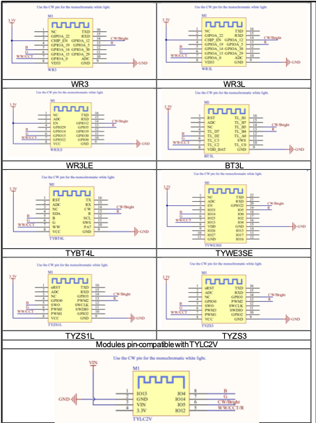
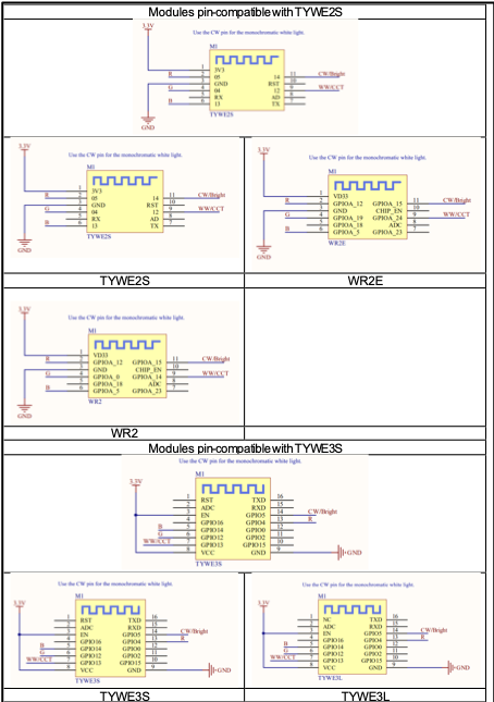
![Step-by-Step Tuya Smart Lighting Product Design](https://images.tuyacn.com/smart/aircondition/light-design63.png)![Step-by-Step Tuya Smart Lighting Product Design](https://images.tuyacn.com/smart/aircondition/light-design59.png)![Step-by-Step Tuya Smart Lighting Product Design](https://images.tuyacn.com/smart/aircondition/light-design60.png)![Step-by-Step Tuya Smart Lighting Product Design](https://images.tuyacn.com/smart/aircondition/light-design61.png)![Step-by-Step Tuya Smart Lighting Product Design](https://images.tuyacn.com/smart/aircondition/light-design62.png)

When the Espressif Systems 8266 chip is being powered on, some I/O interfaces are unstable and have weak output with a high pulse for 180 ms during initialization. As a result, the high level-driven light blinks. To prevent this scenario, connect pull-down resistors whose resistance is less than or equal to 3.3 kiloohms to these I/O interfaces. A lower resistance may be required according to the peripheral circuit. For details, see the following initial pin status table.

**Initial pin status:**

| Pin  | Initial Status  | Recommended Configuration           |
| ---- | --------------- | ----------------------------------- |
| IO2  | Pulled up       | Add an external pull-down resistor. |
| IO4  | High resistance | Add an external pull-down resistor. |
| IO5  | High resistance | Add an external pull-down resistor. |
| IO12 | Pulled up       | Add an external pull-down resistor. |
| IO13 | Pulled up       | Add an external pull-down resistor. |
| IO14 | Pulled up       | Add an external pull-down resistor. |
| IO15 | Low-level       |                                     |
| IO16 | High-level      |                                     |


---

[Next Page](/llms-full.txt/1)