> For the complete documentation index, see [llms.txt](https://docs.ifreeq.com/llms.txt). Markdown versions of documentation pages are available by appending `.md` to page URLs; this page is available as [Markdown](https://docs.ifreeq.com/developer/device-development/access-mode-mcu/wi-fi-general-solution/software-reference-wi-fi/overview-of-migrating-tuyas-mcu-sdk.md).
# Overview of migrating Tuya's MCU SDK
### Introduction
The mcu\_sdk package contains the MCU code that is automatically generated based on product functions defined on the Tuya Smart platform. The communication and protocol resolution architecture is prepared and can be directly added to the original MCU project to quickly develop MCU programs.
### Precautions
The SDK package has the following requirements on MCU hardware resources:
* Flash memory: 4 KB
* RAM: tens of bytes (depending on the DP data length), or 260 KB or higher if the OTA upgrade function is required
* The number of nested functions is 9.
Users without sufficient resources can implement protocol interworking without using the MCU SDK.
### ile Structure
| **Execution File** | **Header File** | **Description** |
| ------------------ | --------------- | ------------------------------------------------------------------------------------------------------------------------ |
| mcu\_api.c | mcu\_api.h | Contain Wi-Fi–related functions. Customers can invoke the functions on demand. |
| protocol.c | protocol.h | Protocol files that contain data processing functions. Users need to modify the two files based on project requirements. |
| system.c | system.h | Contain detailed implementation of the serial port communication protocol. |
| | wifi.h | Contains Wi-Fi–related macro definitions. |
### Roadmap
Step 1: Compile the MCU basic program and migrate the SDK file.
Step 2: Verify the macro definition in protocol.h.
Step 3: Migrate the protocol.c file and invoke functions.
Step 4: Optimize the DP data report and delivery functions.
Step 5: Optimize the network configuration and indicator functions.
Step 6: Optimize the product testing function.
#### Compile the MCU basic program and migrate the SDK file.
Add the .c and .h files in the mcu\_sdk folder and corresponding header file reference path to the original project. Initialize MCU-related peripherals, including the serial port, external interrupt (button), and timer (indicator blinking).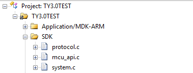
#### Verify the macro definition in protocol.h.
**Verify the product information**
(1) PRODUCT\_KEY is the product PID macro definition, the PID is the unique identifier of each product, which can be copied directly

Please ensure that the code is consistent with the product PID listed on the website, if not download the latest SDK development kit. The download location is as follows: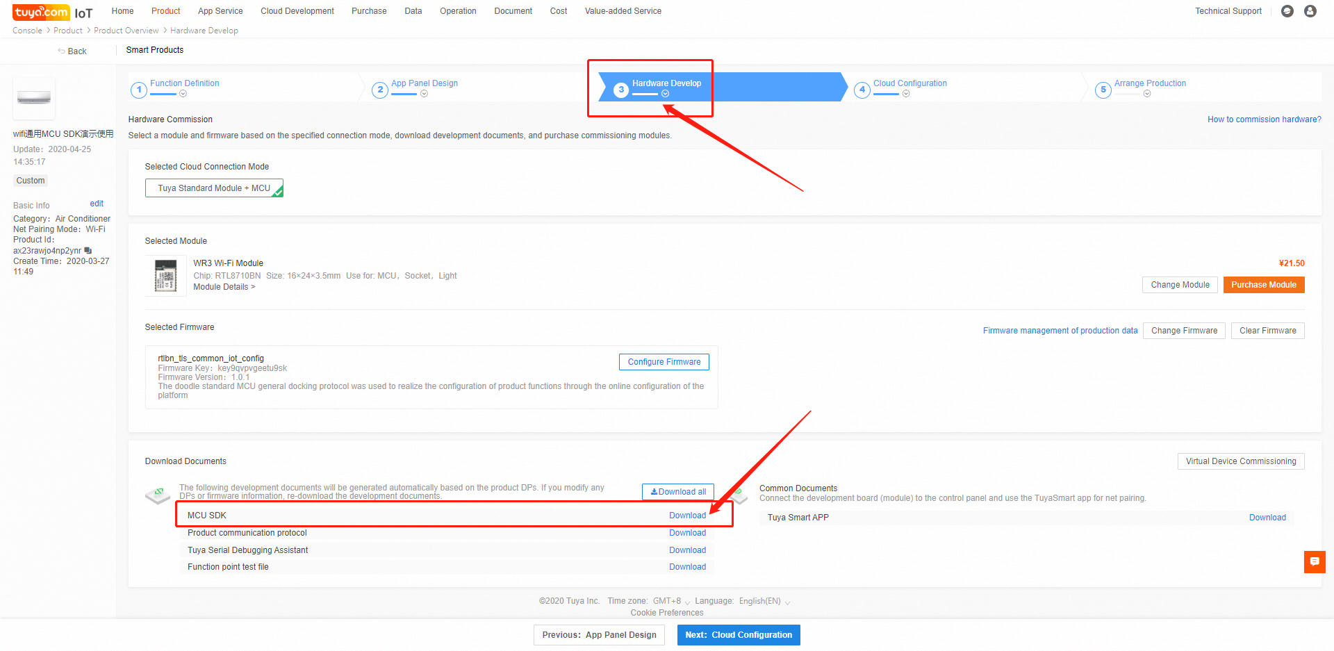(2) MCU\_VER is the software version, the default is 1.0.0. If the MCU needs the OTA function, the new MCU code version number needs to be increased.
(3) CONFIG\_MODE is the network distribution mode, with default (AP and smart switch between each other) mode, security mode, and anti-mistouch mode. It is recommended to select the "anti-mistouch" mode.
Description of three distribution modes: ++Default mode++: AP and smart switch between each other. If the module is not configured or the configuration is removed, it will be in the state of network configuration after power-on and will remain. ++Safe Mode++: The module is in a non-distribution state after it is powered on from the factory. The MCU needs to send a reset command to enter the corresponding distribution mode. When the device is in the distribution state for a period of time (default 3 minutes), it is not When the user configures, the module will re-enter the non-distribution network state, and it needs to receive the reset command again to re-enter the network distribution mode. ++Anti-mistouch mode++: After the module is successfully configured by the user, after the local (MCU sends a reset command) reset, the device is in the state of network configuration, and it has not been reconfigured after a period of time (default 3 minutes). The module will automatically restore the user's network connection before resetting. After the local reset, the device is powered off abnormally, and the user's network connection before reset will be automatically restored after power on. In this mode, only when the device is removed from the APP by the user, the device will not record the last user's network connection and reconnect.

When the security mode or anti-mistouch mode is selected, you can open the CONFIG\_MODE\_DELAY\_TIME macro definition and set the retention time of the distribution mode, the setting range is 3 \~ 10 minutes. If it is not turned on, the default value of 3 minutes will be set.

The smart mode and the smart mode AP of the distribution mode are switched by default, and only one mode can be used at the same time. If you want to use smart and AP coexistence mode, you can open the macro definition CONFIG\_MODE\_CHOOSE to set. When CONFIG\_MODE\_CHOOSE is set to 0, the network configuration mode is coexistence of smart and AP, and there is no need to switch the network configuration mode at this time. When CONFIG\_MODE\_CHOOSE is set to 1, the network configuration mode is only AP mode. Without opening the CONFIG\_MODE\_CHOOSE macro definition, the default configuration mode will be used.

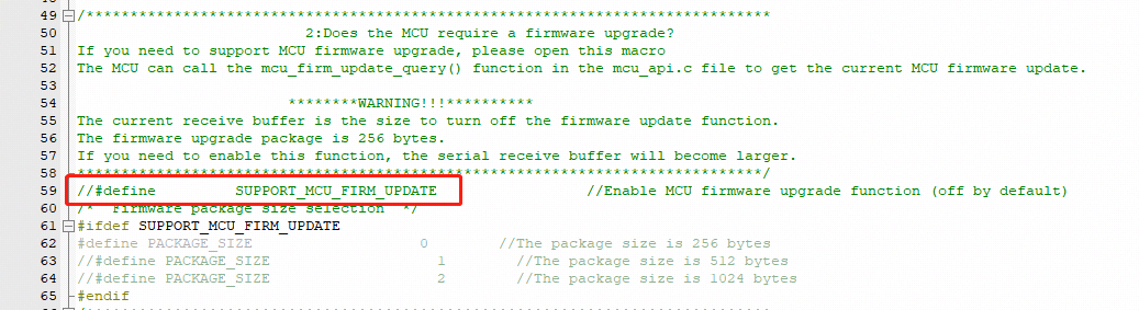
**Check whether the MCU firmware needs to be upgraded**
If OTA upgrade of MCU firmware is required, enable the firmware update macro, which is disabled by default.
OTA upgrade needs to compile the bin file of the MCU code first (must be the bin file, also need to pay attention to increase the version number), and then configure the OTA upgrade on the platform, upload the bin file, then the APP will receive an upgrade reminder (silent upgrade will not Reminder) Click to agree to start the upgrade. After the upgrade is complete, restart the MCU. The module will query the MCU version number to verify whether the upgrade was successful. Several types of OTA (1) App reminder upgrade: In this upgrade mode, users will receive a pop-up window of the upgrade reminder every time they enter the device control panel. Whether to confirm the upgrade is confirmed by the user himself in the app (2) App silent upgrade: This upgrade method App will not have any reminder pop-up window, the firmware will automatically detect the upgrade within one minute after power on and find that there is a higher version of the upgrade package will automatically start to pull the relevant upgrade package After power-on, the module will go to the cloud every 24 hours to check whether there is an upgrade package configuration. (3) App mandatory upgrade: In this upgrade method, there will be an upgrade reminder pop-up window on the App side. If the user does not confirm the upgrade, the user cannot use the product's control panel normally. (4) App detection and upgrade: In this upgrade method, there will not be any pop-up window for upgrade reminder on the App side. Users must click on the relevant firmware version check on the App side. If there is a high-level firmware configuration, the upgrade prompt message will be displayed.
note: (1) OTA generally reads and writes flash. To ensure reliability, it is recommended to read the data just written after each write of flash data and verify the data to be written to ensure that the flash is written. Correctness. (2) It is recommended to add an OTA timeout detection to prevent the MCU from staying in the OTA data reception state when the OTA fails. (3) Each packet of OTA data has packet offset information. The packet offset can be used to detect whether the OTA data packet is heavy or missing.
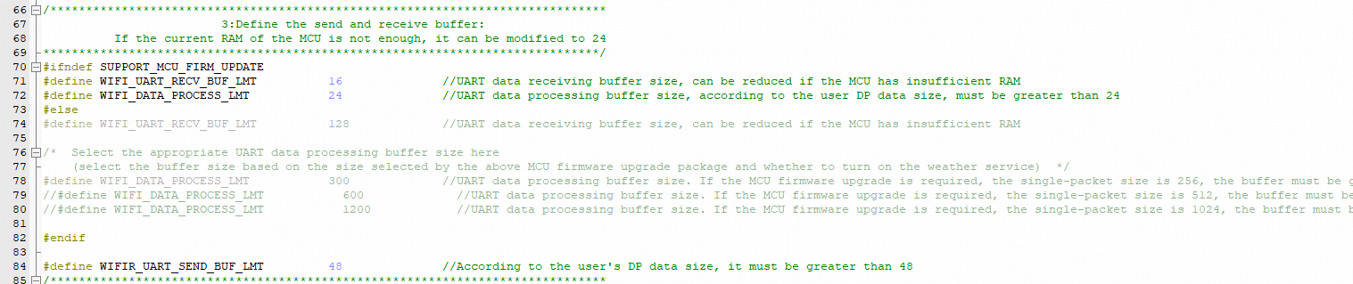
**Define the transmitting and receiving buffers**
The size of the serial port receive buffer is affected by the frequency with which serial data processing is called. If the MCU processes the serial data faster, the serial port receive buffer size can be reduced appropriately; the serial port send buffer size should be greater than the longest DP data length of the data. The serial data processing buffer size should also be greater than the longest DP data length of the data, and the size should be adjusted according to whether the OTA function is required, whether weather services and the number of weather service types, and the number of days are required.
**(Mandatory) Define the working mode of the Wi-Fi module**
1\) If the distribution network trigger and indication are controlled by the MCU (the distribution button and LED are connected to the MCU end), select the "module and MCU co-processing" working mode (commonly used), please keep the WIFI\_CONTROL\_SELF\_MODE macro definition commented

2\) If the Wi-Fi indicator and buttons are connected to the Wi-Fi module (module self-processing working mode), please turn on the WIFI\_CONTROL\_SELF\_MODE macro definition, and then connect the indicator and the GPIO connected to the button according to the actual hardware Fill in the two lines below
**Check whether the Wi-Fi product testing function is enabled**
In order to ensure the final mass production efficiency and quality, it is recommended to open this macro.

Detailed production test process, you can view \[wifi general docking production test documentation]
**Weather service**
If you need the weather service function, you need to open the WEATHER\_ENABLE macro definition

The weather service needs to be opened after the module is successfully connected to the route. After successful opening, the weather data will be delivered after the module is connected to the cloud, and thereafter, it will be delivered every 30 minutes. The weather service also needs to select the type of weather, you can select the options in the array weather\_choose in the protocol.c file,

After selection, write the number to WEATHER\_CHOOSE\_CNT macro definition.

The module of the new firmware will support the weather forecast function for up to 7 days. The number of forecast days can be set in the WEATHER\_FORECAST\_DAYS\_NUM macro definition

When it is set to 1, it means that only the data of the day is obtained. When the setting value is 0 or> 7, the module will reply with an error message and the weather service fails to open. The weather data sent by the module will carry the information of the number of days, 0 means the day, and it needs attention here.
**Streaming service**
Streaming services are generally used for MCUs of the sweeper type, and are mainly used for the transmission of large amounts of data. If necessary, you can open WIFI\_STREAM\_ENABLE macro definition

**Other functions**
For other functions, if necessary, the user can open the corresponding macro definition and perfect related functions.
#### Migrating the protocol.c File and Invoking Functions
1. Use #include "wifi.h" in the files (for example, the main.c file) that require Wi-Fi–related files.
2. After MCU peripherals are initialized, invoke the wifi\_protocol\_init() function in the mcu\_api.c file.
3. Add the single-byte sending function of the MCU serial port to the uart\_transmit\_output function in the protocol.c file and delete #error. The following figure shows an example.

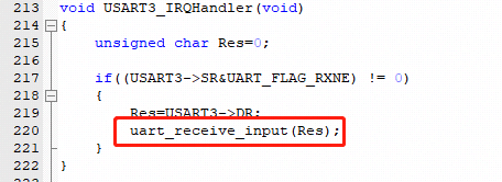
1. Invoke the uart\_receive\_input function in the mcu\_api.c file in the serial port receiving interrupt service function, and use the received characters as parameter input. The following figure shows an example.
1. Invoke the wifi\_uart\_service() function in the mcu\_api.c file after the MCU enters the while cycle. The following shows an example of code structure in main.c.
```
include "wifi.h"
...
void main(void)
{
wifi_protocol_init();
...
while(1)
{
wifi_uart_service();
...
}
}
```
Note: The MCU must directly invoke the wifi\_uart\_service() function in the mcu\_api.c file in while. After the program is successfully initialized, it is recommended that the serial port interrupt not be disabled. If the serial port interrupt must be disabled, ensure that the interrupt is disabled for only a short time to prevent serial port data loss. Do not invoke the report function in the interrupt.
#### Processing DP Data Report and Delivery Functions
There are 6 main types of dp (1) bool type: The bool type is generally the dp of some switches, such as switch, ECO, and screen display. (2) Enum type: The enum type is generally used as dp with various states, such as working mode, wind speed, wind swing position. (3) Value type: The value type is generally used as the value type dp, such as the set temperature value, current temperature value, and power. (4) Fault type: The fault type is generally used for fault reporting, and the data is usually performed in bitmap format. (5) String type: String is generally used as a string type dp, some dp need to be transmitted in the form of a string, you can use this type. There are some dp that are inconvenient to use bool, enum, value, fault type, this type can also be used. (6) Raw type: The raw type is generally used for data that needs to be transparently transmitted. There is no requirement for the data format. Plain text or encryption can be used. When using it, the sender and receiver must communicate the data format, package and parsing method.
**Reporting data of all DPs**
After the Wi-Fi module restarts or the network is reconfigured, the Wi-Fi module proactively delivers a status query command. The MCU needs to report the status of the device's DPs to the Wi-Fi module for synchronization. (1) Open protocol.c and locate the all\_data\_update(void) function. (2) Enter initial values of all DPs to be reported into corresponding report functions. The values will be displayed on the App control panel. Note: Do not invoke the all\_data\_update() function manually. This function is automatically invoked at a specific time.

**Reporting data of a single DP**
When the status of a DP is changed, the MCU proactively reports the new DP status to the Wi-Fi module, and the DP status displayed on the App will be updated accordingly. The report data format is mcu\_dp\_xxxx\_updata(DPID\_X,n). DPID\_X indicates the DP whose status has changed. Functions in all\_data\_update() can be independently invoked. Example:
```
mcu_dp_bool_update(DPID_SWITCH,1); //Boolean data reporting
mcu_dp_value_update(DPID_TEMPER_SET,25); //Value data reporting
mcu_dp_string_update(DPID_DAY,"1234",4); //String data reporting
```
**DP data delivery**
Each deliverable DP has an independent data delivery processing function in the protocol.c file. The function format is dp\_download\_xxx\_handle(), and xxx indicates a deliverable DP. After the function parses a DP, the MCU performs logical control in the corresponding position. The following shows an example of receiving switch data.The MCU uses MCU\_ON\_switch1() and MCU\_OFF\_switch1() to turn on and off a switch, respectively. When the device status is changed under non-App control, the MCU invokes mcu\_dp\_bool\_update(DPID\_SWITCH\_1,switch\_1) to upload the real status of the switch. Typically, the receiving processing function automatically invokes the function.
#### Optimize the network configuration and indicator functions.
Skip this section if processing by the Wi-Fi module is used. When protocol migration is successful, the network configuration command and indicator function need to be optimized for network configuration. In mode of cooperative processing by the Wi-Fi module and MCU, the MCU can select the network configuration triggering and indication modes based on actual requirements. Typically, network configuration is triggered by the Wi-Fi reset button and indicated by quick or slow blinking of the Wi-Fi indicator. We recommend that you enable both network configuration modes for your product. Smart network configuration mode: The operation is simple and convenient, and the Wi-Fi indicator blinks quickly. AP network configuration mode: Network configuration is reliable, and the Wi-Fi indicator blinks slowly.
**Network configuration command**
The network configuration command can be implemented by the mcu\_reset\_wifi() and mcu\_set\_wifi\_mode() functions. Typically, these two functions are invoked in the button processing function after the button is pressed for network configuration. After mcu\_reset\_wifi() is invoked, the Wi-Fi module is reset and the previous network configuration information is cleared. The function invoking also triggers a switchover between the AP and smart network configuration modes.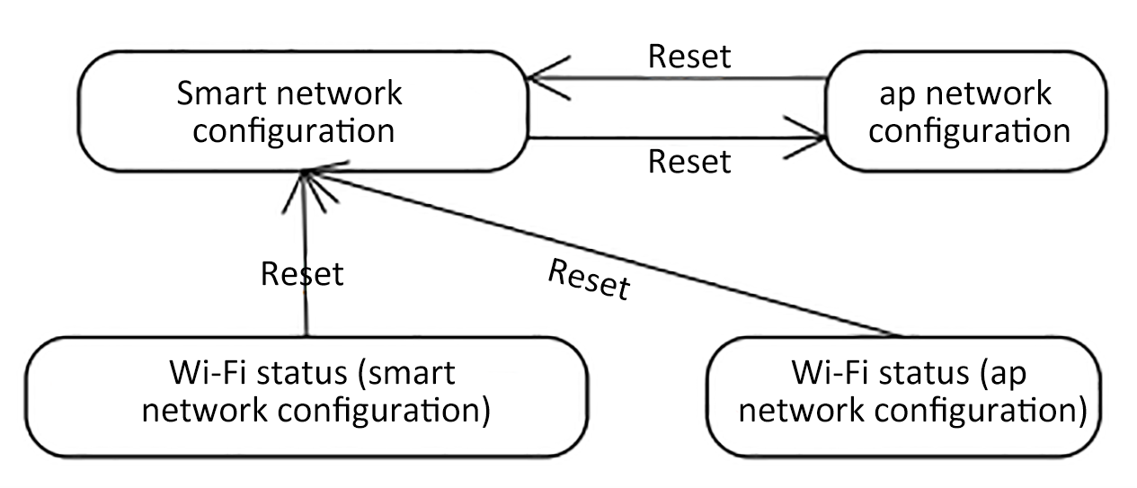
After mcu\_set\_wifi\_mode() with parameter SMART\_CONFIG or AP\_CONFIG is invoked, the network configuration information is cleared, and smart or AP network configuration mode is used. This function has the same function as the mcu\_reset\_wifi() function. You can select one as needed.
**Network configuration indication**
Typically, the mcu\_get\_wifi\_work\_state() function is invoked at while(1) to return the Wi-Fi status. Then, you write the indicator blinking mode in based on the Wi-Fi status.
| Device Network Connection Status | Description | Status Value | LED Indicator Status |
| -------------------------------- | ---------------------------------------------------------------------------- | ------------ | ------------------------------------------ |
| State 1 | Smart network configuration | 0x00 | The indicator blinks at 250 ms intervals. |
| State 2 | AP network configuration | 0x01 | The indicator blinks at 1500 ms intervals. |
| State 3 | The Wi-Fi is configured. However, the device fails to connect to the router. | 0x02 | The indicator is off. |
| State 4 | The Wi-Fi is configured, and the device successfully connects to the router. | 0x03 | The indicator is steady on. |
| State 5 | The device connects to the router and cloud. | 0x04 | The indicator is steady on. |
| State 6 | The Wi-Fi device is in low power consumption mode. | 0x05 | The indicator is off. |
| State 7 | The Wi-Fi device is insmartconfig\&AP consumption mode. | 0x06 | TThe indicator blinks at 250 ms intervals. |
Invoke the mcu\_get\_wifi\_work\_state() function to obtain the Wi-Fi status. The function architecture is as follows:
```
void main(void)
{
...
while(1)
{
switch(mcu_get_wifi_work_state())
{
case SMART_CONFIG_STATE:
//smart config configuration state: LED flash quickly; the user needs to complete the configuration
break;
case AP_STATE:
//AP configuration state: LED flash slowly
break;
case WIFI_NOT_CONNECTED:
//Wi-Fi configuration is finished; the router is being connected to; LED keeps long dark
break;
case WIFI_CONNECTED:
//The router is successfully connected to; LED keeps long bright
break;
default:break;
}
...
}
}
```
Description of network status:
| Device Network Connection Status | Description | Description |
| -------------------------------- | ---------------------------------------------------------------------------- | ------------------------------------------------------------------------------------------------------------------------------------------------------------------------------------------------------------------- |
| State 1 | Smart network configuration | The wifi module is in smart distribution state |
| State 2 | AP network configuration | wifi module is in AP configuration |
| State 3 | The Wi-Fi is configured. However, the device fails to connect to the router. | The wifi module has received configuration information and is connecting to the router |
| State 4 | The Wi-Fi is configured, and the device successfully connects to the router. | The wifi module is connected to the router, but is not connected to the cloud. If the module has been equipped with a network and the mobile phone is also connected to this route, it can be controlled by the LAN |
| State 5 | The device connects to the router and cloud. | The wifi module has been connected to the cloud, and both the LAN and the external network can be controlled at this time |
| State 6 | The Wi-Fi device is in low power consumption mode. | wifi module enters low power consumption state |
| State 7 | The Wi-Fi device is insmartconfig\&AP consumption mode. | The wifi module is in smart & AP state, at this time, it can be either smart or AP. |
#### Perfect production test function
The production test has the following three forms, you can choose according to your product docking situation \* Common platform Wi-Fi function test process-scan specified route \* Common platform Wi-Fi function test process-connect designated route \* Common platform Wi-Fi function test process-infrared function test
The specific process can be viewed: \[Wi-Fi General Production Test Documentation]
### MCU\_SDK and module data communication guide
The frame format can refer to the protocol description document in the SDK development kit
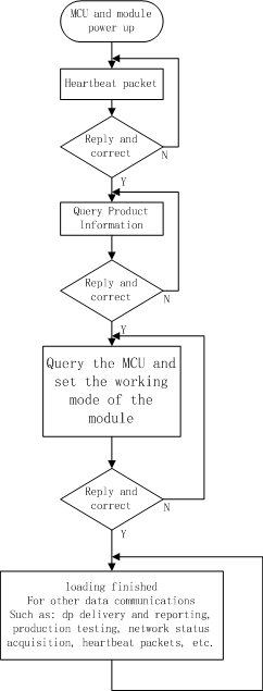
#### Initialize communication
After the MCU and the module are powered on, some initial configuration is required. During this period, it is necessary to verify whether the MCU and the module can work normally, whether the communication connection is normal, the data required for the module activation, and the module acquisition work method.
**Heartbeat packet**
The heartbeat packet is the data for regular communication between the MCU and the module. It can be used as a basis for verifying whether the MCU or the module is working properly. Therefore, it is recommended that the frame for the first communication after the MCU and the module are powered on is the heartbeat packet. Only when the heartbeat packet is sent and the reply is normal, can the communication be continued.
**Query product information**
After the heartbeat package can interact normally, the module needs to query the product PID, version number, and network configuration method of the MCU firmware. The PID is used for product activation. The version number is used to verify whether the upgrade is successful after the OTA upgrade is completed. The distribution network mode of the module.
**Query MCU, set the working mode of the module**
Used to set the working mode of the module, select the MCU and module co-processing mode or module self-processing mode It can be selected according to the WIFI network status indicator and the hardware connection position of the module reset button.
#### Data interaction process
#### Data interaction considerations
Special Note: 1. In order to avoid unpredictable problems, it is recommended that normal data communication such as dp delivery and reporting, OTA upgrade, etc. should be performed after initialization is completed. 2. For devices with low power consumption and other MCUs that can control the power of the module, data interaction must be performed after the device is initialized.