> For the complete documentation index, see [llms.txt](https://docs.ifreeq.com/llms.txt). Markdown versions of documentation pages are available by appending `.md` to page URLs; this page is available as [Markdown](https://docs.ifreeq.com/developer/device-development/access-mode-soc/lighting/guidance.md).
# Guidance
### Preface
The Tuya Smart platform provides plug-and-play solutions with the Wi-Fi, BLE Mesh (SIG), Zigbee, and BLE Mesh (Tuya) communication modes for LED lighting products, including dimmable white lamps (C), CW or CCT lamps, RGB lamps, RGBC lamps, and RGBCW or RGBCCT lamps.
This document describes how to use a plug-and-play solution to develop a Wi-Fi RGBCW lamp on the Tuya Smart platform and the precautions.
### Registering with and Logging In to the Tuya Smart Platform
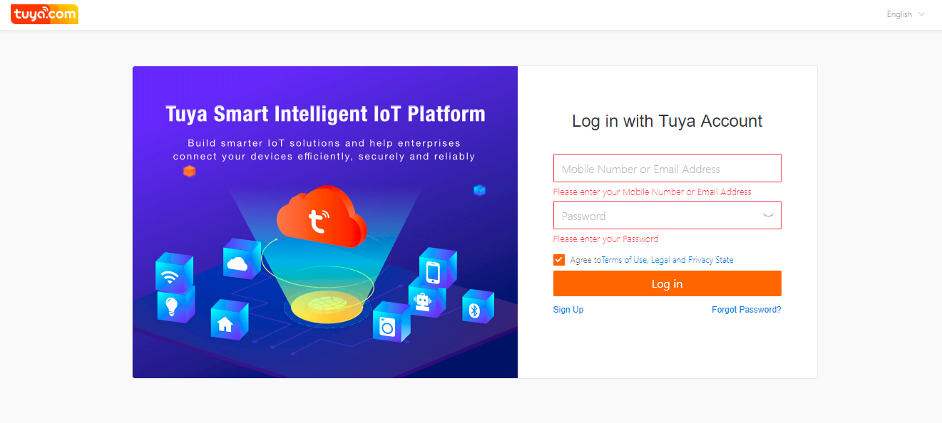
1. Register with and log in to the Tuya Smart platform at .
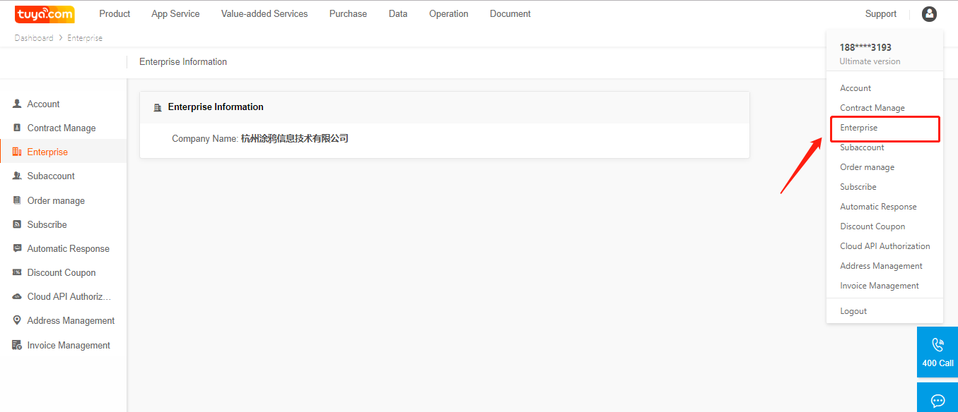
2. (Recommended) Complete enterprise certification to upgrade your account to a corporate account with more functions.
### Creating an SoC Plug-and-Play RGBCW Lamp
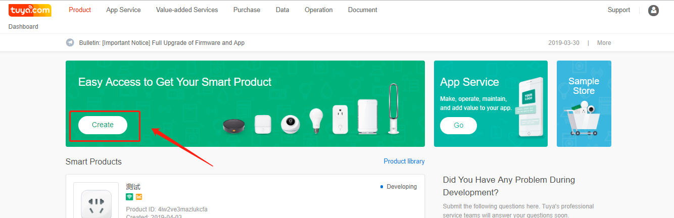
1. On the **Product** page, click **Create** in the **Easy Access to Get Your Smart Product** area.
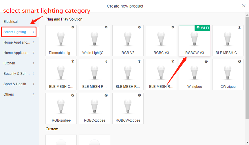
2. (Recommended) On the displayed **Create new product** page, choose **Smart Lighting** and select a product under **Plug and Play Solution**. Alternatively, select a product under **Custom** if the development-free solution cannot meet your product function requirements.
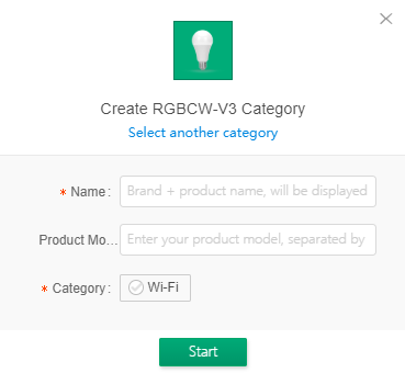
1. Specify the product name, which will be displayed on the App control panel.
2. Specify the internal or customer product model to facilitate product maintenance and order management.
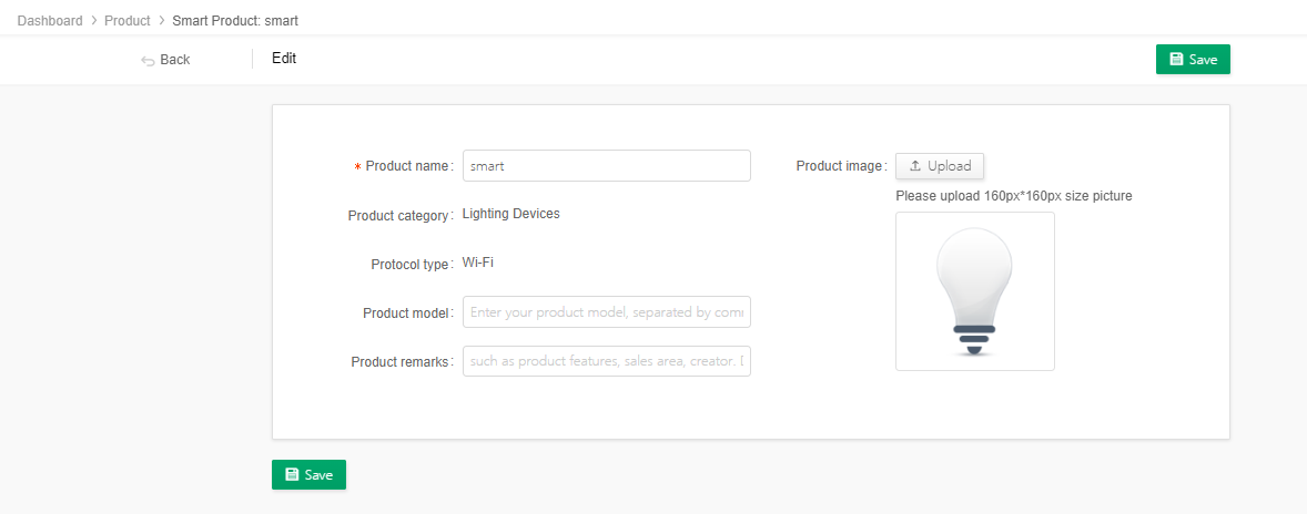
3. After the product is created, click **Edit Product Information** on the product configuration page to modify the product name and model.
4. If you subscribe to a third-party service for the product, the third-party service subscription icon is highlighted for the product on the **Product** page.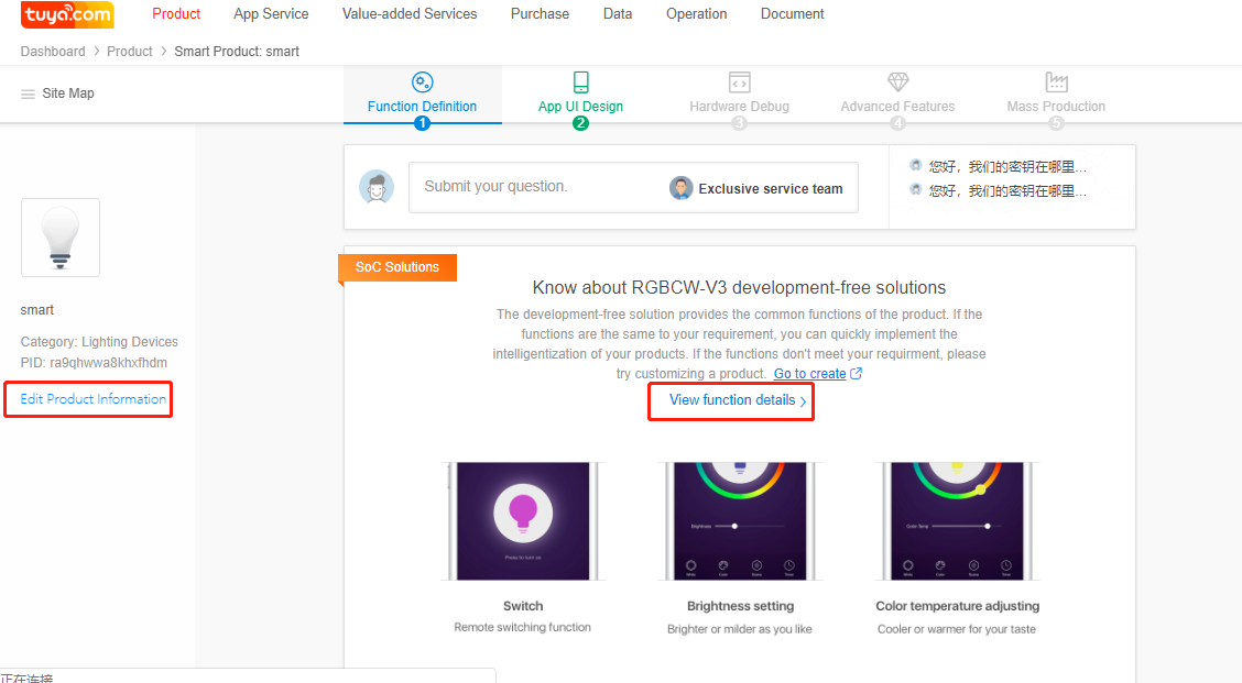
### Viewing DPs
You cannot modify data points (DPs) of a plug-and-play solution. To view the DPs, click **View function details**.
### Configuring the App Control Panel
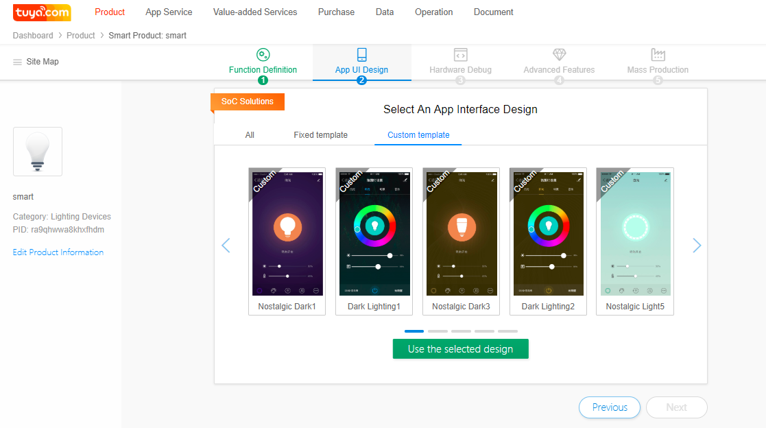
1. Click **App UI Design**. If you have upgraded your account to a corporate account, more templates and panel UI functions are available.
2. Select a control panel template and use the Tuya Smart or Smart Life App to scan the QR code to verify the control panel effect.
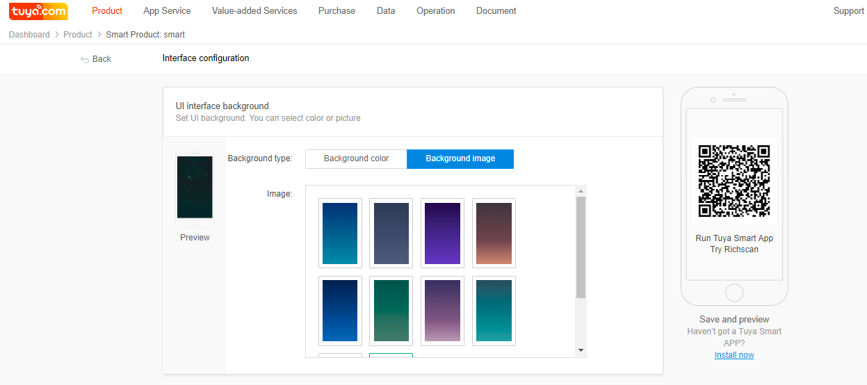
3. If you select a custom panel, click **Edit** to change panel elements, such as the background color and image.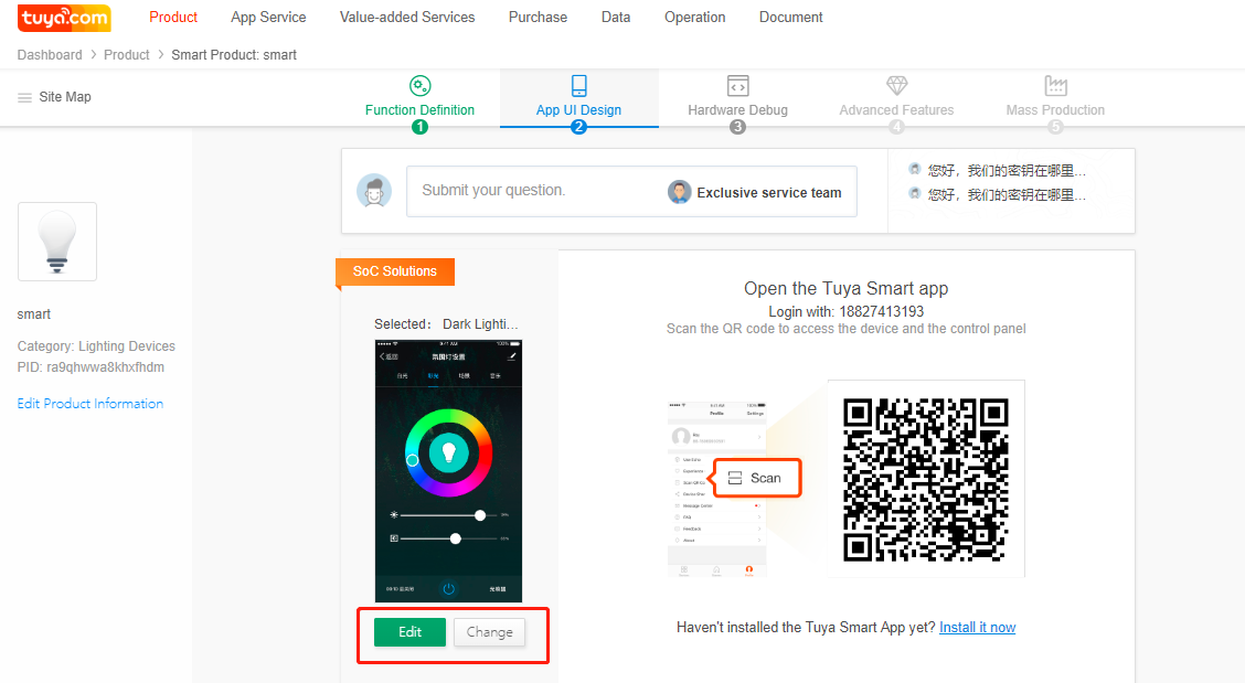
### Debugging the Hardware
Perform operations in this chapter to configure the module's electrical parameters. It is recommended that engineers perform these operations because setting the parameters requires professional knowledge.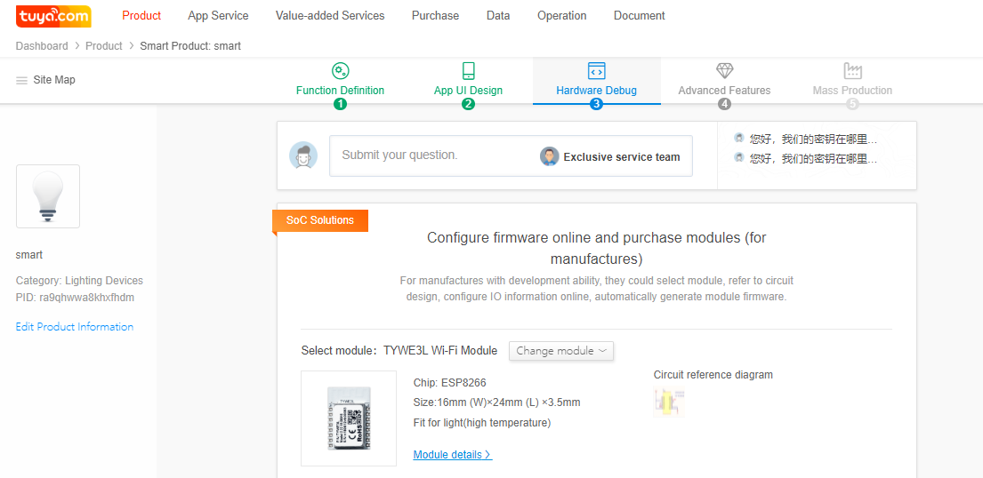
#### Selecting a Module and Checking the Reference Circuit Diagram (If you change the module, the reference circuit diagram will be updated.)
Select a module based on the product encapsulation, placement space, temperature, and antenna type. The Tuya Smart platform provides 10 Wi-Fi modules with their hardware design manuals and I/O interface connection diagrams. Note: The EN pins on the E3S and E3L modules need to be pulled up to a high level. Pay attention to the RF signal reference design. Modules recommended for different lighting products are as follows:
* Bulbs: TYE3L
* Filament lamps: TYLC5
* Candle lamps or GU10 bulbs: TYLC4
* Built-in power lamps or power lamps with metal covers: TYE1S-IPEX (supporting an external antenna)
* Power lamps with a plastic cover: TYE1S with an onboard antenna or TYE3S
* Compact products, such as light strip controllers: TYE2S
#### Configuring Module Firmware I/O Interface Information
**IIC Configuration**
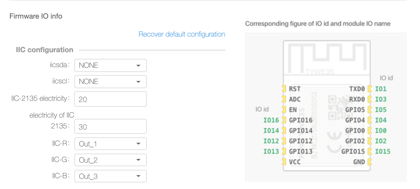
a) **IIC Data I/O Interface**: indicates the data I/O interface for IIC communication. Five I/O interfaces are available. If IIC communication is not required, select **None**. The first I/O interface is the default I/O interface.
b) **IIC Clock Signal I/O Interface**: indicates the clock signal I/O interface for IIC communication. Five I/O interfaces are available. If IIC communication is not required, select **None**. The first I/O interface is the default I/O interface.
c) **IIC-2135 Color Light Current**: indicates the RGB light current when the SM2135 chip that uses the IIC protocol is used. The value range is 10 mA to 45 mA.
d) **IIC-2135 White Light Current**: indicates the CW light current when the SM2135 chip that uses the IIC protocol is used. The value range is 10 mA to 60 mA.
e) **IIC-R**, **IIC-G**, **IIC-B**, **IIC-2135-W**, and **IIC-2135-C**: indicate pins on the SM2135 that control the red, green, blue, cold white, and warm white light when the SM2135 chip that uses the IIC protocol is used.
**Product Function**
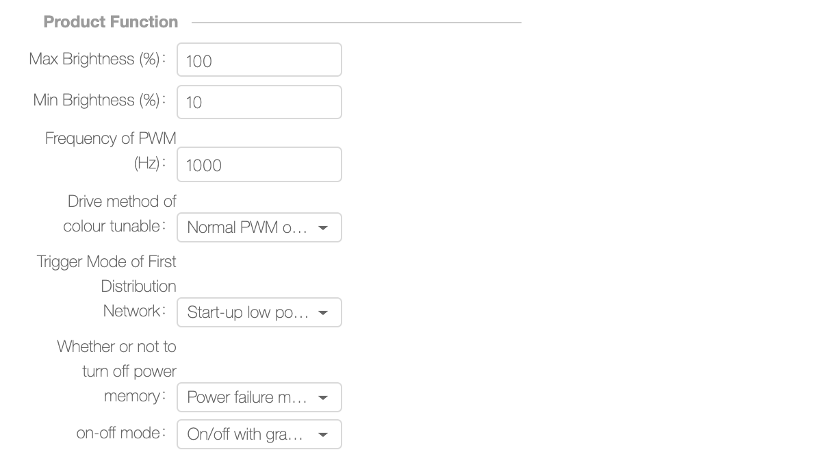
a) **Max Brightness (%)** and **Min Brightness (%)**: indicate the maximum and minimum duty cycles of the PWM waveforms generated by the I/O interfaces for the cold and warm white light. The value range is 1 to 100.
Note: The **Min Brightness (%)** parameter must be set based on the dimming depth of the selected dimmable integrated circuit (IC). If they do not match, the lamp will turn off in low brightness. The default minimum brightness is 10%.
b) **PWM Frequency (Hz)**: indicates the frequency of each PWM control signal. The value range is 100 Hz to 20,000 Hz.
Note: The **PWM Frequency (Hz)** parameter must be set based on the PWM frequency that the dimmable IC supports. The frequency of most PWM ICs on the market is in the range of 500 Hz to 5000 Hz. When you adjust the frequency to 8000 Hz or higher, ripples in the light are invisible under the mobile phone camera.
c) **Color Temperature Drive Method**: Options are **CW-Cold/Warm** and **CCT-Brightness/Color Temperature**. The two methods have the same functions and UIs in the App and can control the color temperature and adjust the light brightness. They vary in the design of the peripheral circuit. For a CCT lamp, the two channels of PWM signals are independent of each other, with one controlling the overall current and the other adjusting the current proportions of the warm and cold light. Only one channel of PWM signals changes when you adjust the brightness or color. For a CW lamp, one channel of PWM signals controls the cold light while the other controls the warm light. Both channels of PWM signals change when you adjust the brightness or color. CW and CCT lamps are Tuya's internal classification methods. In the industry, CCT lamps are those with a color temperature adjustment feature, which are different from the CCT lamps in Tuya.
Note: This parameter is important. An incorrect value will cause incorrect light control logic. If you are not sure which value to select, send the schematic diagram to Tuya engineers for confirmation.
d) **Color Drive Pin Connection Method**: The options are **Normal PWM Output**, **CW-PWM+RGB-I2C(16726)**, and **CW- I2C(sm2135)+RGB-I2C(sm2135)**. **Normal PWM Output** indicates that three I/O interfaces generate PWM signals to control the red, green, and blue light. **CW-PWM+RGB-I2C(16726)** indicates that the IIC communication method controls the red, green, and blue light between the module and the SM726EB linear IC. **CW- I2C(sm2135)+RGB-I2C(sm2135)** indicates that the IIC communication method controls the red, green, and blue light between the module and the SM2135 linear IC. Note: If you select an incorrect method, the lamp cannot be controlled.
e) **First Network Configuration Trigger Mode**: indicates the method for the module to enter the network configuration mode. **Blink After Power Cycling** indicates that you power-cycle the module several times or press and hold the network configuration button for several seconds to enter the network configuration mode. **Blink After Power-on** indicates that the module automatically enters the network configuration mode after being powered on.
f) **Power-off Memory**: The options are **Power-off Memory** and **Restore to the Default State After Power Cycling**. **Power-off Memory** indicates that the module status remains unchanged each time the product is powered on. However, the status must be retained for over 5s before the product is powered off. **Restore to the Default State After Power Cycling** indicates that the white light is displayed with the default brightness and color temperature after the module enters the network configuration mode. For details on how to set the brightness and color temperature, see "(3) Network Configuration."
g) **On/Off Gradual Change**: indicates whether the module's PWM signal gradually changes from the current duty cycle to 0 when the product is powered off and gradually increases from 0 when being powered on. The options are **Yes** and **No**.
**Network Configuration**
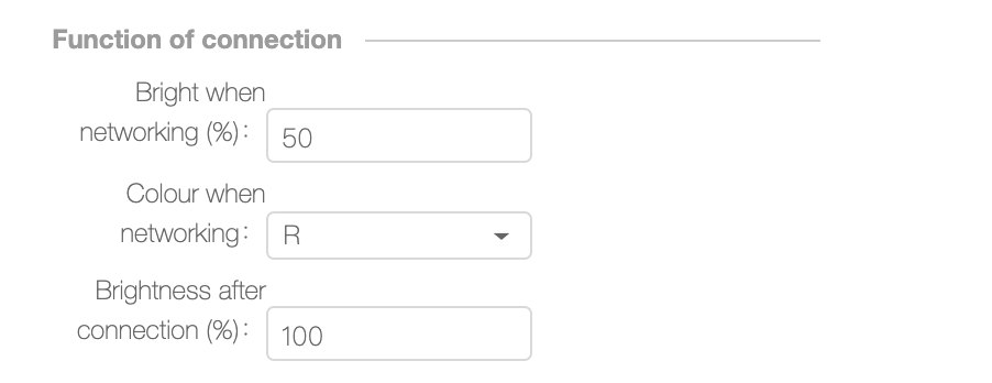
a) **Brightness upon Network Configuration (%)**: indicates the blinking light brightness during network configuration. The value indicates the duty cycle of the PWM signal. The value range is 10 to 100. Note: The minimum dimming depth of some dimmable ICs is 10%. If **Brightness upon Network Configuration (%)** is set to **10**, the lamp will turn off during network configuration and will not blink. It is recommended that **Brightness upon Network Configuration (%)** be greater than 20.
b) **Color upon Network Configuration**: indicates the light blinks in network configuration mode. The options are **R**, **G**, **B**, **C**, and **W**.
c) **Brightness After Network Configuration (%)** and **Color Temperature After Network Configuration**: indicate the white light brightness and color temperature after network configuration. The values are the duty cycles of the PWM signals for controlling the white light brightness and color temperature. Note: The brightness value must be greater than the minimum dimming depth of the dimmable IC, or the lamp will turn off after network configuration. Consumers may think that the lamp is faulty.
**I/O Settings**
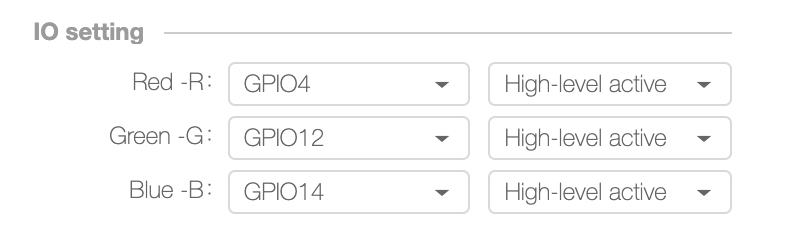
Select the I/O interfaces and levels for the red, green, blue, cold white (bright), and warm white (CCT) control signals.
**Network Configuration Settings**
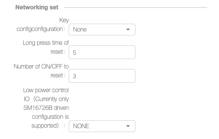
a) **Network Configuration Button**: indicates whether you can press and hold a button to enter the network configuration mode. The options are **None** and multiple I/O interfaces. The value **None** indicates that you cannot press and hold a button to enter the network configuration mode. If an I/O interface is selected, you can press and hold this button to enter the network configuration mode. Note: Select **None** if you do not need to press and hold the network configuration button to enter the network configuration mode. If an I/O interface is selected but not used, the module may be powered on or off unexpectedly.
b) **Button Pressing Time (s)**: indicates the time for pressing and holding the button to enter the network configuration mode. The value range is from 3s to 10s. If **Network Configuration Button** is set to **None**, this parameter does not need to be specified.
c) **Number of Resets**: indicates the number of resets for the module firmware to enter the network configuration mode. The value range is 3 to 10. Note: To power cycle the module's Vcc pin, power cycle the lamp. During network configuration, ensure that the voltage of the Vcc pin is Approaching 0 V before you power the lamp on.
d) **Low-power Control Pin**: indicates the low-power pin during IIC control. Currently, the pin can be configured only under the SM16726B drive. That is, this parameter needs to be specified only if **Color Drive Pin Connection Method** is set to **CW-PWM+RGB-I2C(16726)**.
Note: After all the parameters are configured, click **Save** on the top of the page for the parameters to take effect.
#### Purchasing Modules
After completing the configuration, click **Purchase** to purchase a small number of the modules for product debugging.
**Note: The module will be burned based on the settings that you specify on this page. After the module is delivered, the settings cannot be modified. To modify the settings, repurchase a module. If you modify the settings after the module is delivered, any online upgrades will not apply to the product because the settings will be inconsistent.**
### Configuring Advanced Features
For details on how to configure advanced features, visit .
### Mass Production
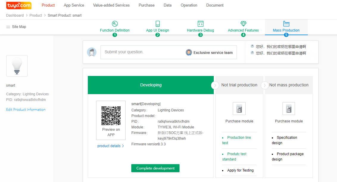
1. After you receive the sample modules and complete product debugging, send at least two product samples to Tuya for testing and verifying the product status.
2. After the sample product passes the test, click **Complete development** to enter the trial production phase.
3. After trial production is completed, click **Pass test, to mass production**. In the mass production phase, product settings cannot be modified to prevent misoperations and impact on consumers.
4. Do not delete products that are under development or have been developed to prevent data loss and causing the product to fail to function properly.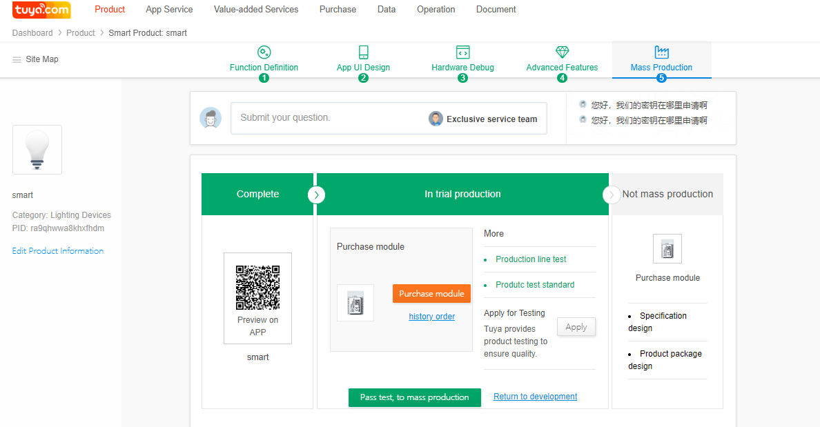
---
# Agent Instructions
This documentation is published with GitBook. GitBook is the documentation platform designed so that both humans and AI agents can read, navigate, and reason over technical content effectively. Learn more at gitbook.com.
## Querying This Documentation
If you need additional information that is not directly available in this page, you can query the documentation dynamically by asking a question.
Perform an HTTP GET request on the current page URL with the `ask` query parameter, and the optional `goal` query parameter:
```
GET https://docs.ifreeq.com/developer/device-development/access-mode-soc/lighting/guidance.md?ask=&goal=
```
`ask` is the immediate question: it should be specific, self-contained, and written in natural language.
`goal` is optional and describes the broader end goal you are ultimately trying to accomplish on behalf of the user. GitBook uses it to tailor the answer towards what is most useful for that goal.
The response will contain a direct answer to the question and relevant excerpts and sources from the documentation.
Use this mechanism when the answer is not explicitly present in the current page, you need clarification or additional context, or you want to retrieve related documentation sections.