> For the complete documentation index, see [llms.txt](https://docs.ifreeq.com/llms.txt). Markdown versions of documentation pages are available by appending `.md` to page URLs; this page is available as [Markdown](https://docs.ifreeq.com/developer/device-development/access-mode-mcu/wi-fi-general-solution/software-reference-wi-fi/tuya-cloud-universal-serial-port-access-protocol.md).
# Tuya Cloud Universal Serial Port Access Protocol
| Protocol version | Date |
| ---------------- | -------- |
| 1.2.3 | 20200521 |
### 1、Serial communication conventions
Baud rate: 9600/115200
Data bits: 8
Parity: None
Stop bits: 1
Data flow control: None
MCU: User control board control chip, connected with Tuya module through serial port.
### 2、Frame Format Description
| Field | Length (byte) | Description |
| ------------ | ------------- | --------------------------------------------------------------- |
| Frame Header | 2 | Fixed at 0x55aa |
| Version | 1 | Upgrade and Expansion |
| Command word | 1 | Specific frame type |
| Data Length | 2 | Big Endian |
| Data | N | |
| Checksum | 1 | Byte-sum results from the beginning of the frame, 256 remainder |
Explanation:
* All data larger than 1 byte is transmitted in big-endian mode.
* Under normal circumstances, the same command word is used to send and receive synchronization mechanism, that is, one party sends a command and the other responds. If the sender does not receive the correct response packet after timeout, the timeout is transmitted, as shown in the figure below:

Note: The specific communication method is subject to the "Protocol Details" section.
* The module control command is issued and the MCU status is reported in asynchronous mode. Assuming that the module control command is issued with the "command word" as x and the MCU status is reported with the "command word" as y, as follows:
* Module control command is issued:

* MCU status report:

### 3、Protocol details
### 3.1、Heartbeat detection
Explanation:
1. After the WIFI module is powered on, it periodically sends heartbeats at 15s intervals. If no response is received from the MCU within the timeout period (3s), the MCU is considered offline.
2. The MCU can also periodically check whether the module is working properly based on this heartbeat. If the module is issued without a heartbeat, the MCU can reset the WIFI module through the hardware reset pin provided by the module.
Module sends:
| Field | Length (byte) | Description |
| ------------ | ------------- | --------------------------------------------------------------- |
| Frame Header | 2 | 0x55aa |
| Version | 1 | 0x00 |
| Command Word | 1 | 0x00 |
| Data length | 2 | 0x0000 |
| Data | 0 | None |
| Checksum | 1 | Byte-sum results from the beginning of the frame, 256 remainder |
Example: 0x55aa 00 00 0000 ff
The MCU returns:
| Field | Length (byte) | Description |
| ------------ | ------------- | ---------------------------------------------------------------------------------------------------------------------------------------------------------------------------------- |
| Frame Header | 2 | 0x55aa |
| Version | 1 | 0x03 |
| Command Word | 1 | 0x00 |
| Data length | 2 | 0x0001 |
| Data | 1 | 0x00: The first heartbeat return value after the MCU restarts, sent only once, used by the module to determine whether the MCU restarts during the work process. Return this value |
| Checksum | 1 | Byte-sum results from the beginning of the frame, 256 remainder |
Example: 0x55aa 03 00 0001 00 03 (MCU returns for the first time)
0x55aa 03 00 0001 01 04 (except for the first time, return normally)
### 3.2、Query Product Information
Explanation:
1. Product ID: Corresponds to the Tuya Developer Platform PID (product identification), which is generated by the Tuya Cloud Developer Platform and used to record product-related information in the cloud.
2. Product information consists of product ID and MCU software version
3. MCU software version number format definition: in dotted decimal form, "x.x.x" (0 \ <= x \ <= 99), x is a decimal number
Module sends:
| Field | Length (byte) | Description |
| ------------ | ------------- | --------------------------------------------------------------- |
| Frame Header | 2 | 0x55aa |
| Version | 1 | 0x00 |
| Command Word | 1 | 0x01 |
| Data length | 2 | 0x0000 |
| Data | 0 | None |
| Checksum | 1 | Byte-sum results from the beginning of the frame, 256 remainder |
Example: 0x55aa 00 01 0000 00
The MCU returns:
| Field | Length (byte) | Description |
| ------------ | ------------- | ---------------------------------------------------------------------------- |
| Frame Header | 2 | 0x55aa |
| Version | 1 | 0x03 |
| Command Word | 1 | 0x01 |
| Data Length | 2 | N |
| Data | N | {“p”:”AIp08kLIftb8x2x0”,“v”:”1.0.0”,”m”:1,”mt”:10,”n”:0,”ir”:”5.12”,”low”:0} |
| Checksum | 1 | Byte-sum results from the beginning of the frame, 256 remainder |
Example: {“p”:”AIp08kLIftb8x2x0”,“v”:”1.0.0”,”m”:1,”mt”:10,”n”:0,”ir”:”5.12”,”low”:0}
Product information field description:
1\) p means the product ID is AIp08kLIftb8x2x0, which is the product ID created by the user on the Tuya IOT platform.
2\) v indicates that the MCU version is 1.0.0, and the MCU version number format needs to be defined in the format of x.x.x
3\) m indicates the working mode of the module: 0-normal distribution network working mode, 1-overtime distribution network working mode, 2-anti-mistouch working mode.
**normal distribution network working mode:** After leaving the factory, the module has been in the state of network distribution and has been maintained.
**overtime distribution network working mode:** The module is in a non-distribution state after it is powered on from the factory and requires the MCU to send a reset command before entering the corresponding distribution mode The device will enter the non-distribution state again after the module is in the distribution state for three minutes without the user distributing the module. The command will re-enter the network configuration mode.
**anti-mistouch working mode:** After the module is configured by the user locally (the MCU sends a reset command), the device is in the network to be configured If the status is not configured for three minutes, it will automatically restore the user's network connection before reset. The device breaks abnormally halfway after local reset Power on will also automatically restore the user's network connection before reset. In this mode, only when the device is moved from the APP by the user Except for the device, it will not record the last user's network connection and reconnect. This mode is for users who need local reset The needs of the scene.
4\) mt field (optional): Set the state switching time of safe mode and anti-mistouch mode, without uploading this field, follow the old mechanism Three minutes processing, can support the set time range: 3 minutes \~ 10 minutes.
5\) n field (optional): indicates the network configuration mode of the mode. Without this field, the traditional two-network mode switching mode is maintained: 0-smartconfig & AP coexistence distribution network mode The module supports both AP connection and EZ distribution without user switching. For the corresponding distribution status package, see 1-Only AP configuration mode In this mode, the product can only be configured through AP connection.
6\) ir field (optional): enable the infrared function of the module and inform the module that the infrared transceiver pins use those IO ports. Without this field, the infrared capability is turned off by default 5.12: the infrared transmit pin is IO5, and the infrared receive pin is IO12. Note that if the module self-processing mode is used in the working mode, do not repeat it with the IO port set according to the WIFI indicator light. Part of the module cross-group IO setting, you need to add 32 to the base of the setting group IO, PB20 set the serial number to 20+32. The infrared sending pin needs to use PWM resources, and the receiving needs to use IO interrupt. The specific module supports the IO port reference module information.
7\) low field (optional): Whether the module is turned on to maintain a low-power mode for long connection, without this field, the low-power mode is turned off by default. For some products, when there is no network control, the average power consumption of the module needs to be lower than 15MA under the connection of the module to maintain and route. Through this field, we can open the ability of the module. After the dual-mode module turns on this function, the module has only the Bluetooth distribution function, and the Bluetooth control will be turned off. Products that do not require power consumption do not need to care about this field. 0-turn off low power mode 1-Turn on the module low power mode
### 3.3、Query MCU and set the module's working mode
Explanation:
1. The module working mode is mainly for how to indicate the working status of WIFI and how to reset WIFI. There are mainly two cases:
a. MCU cooperates with the module, that is, the module notifies the MCU through the serial port The current working status of WIFI is supported by the MCU; the MCU detects the need to reset the WIFI and informs the module to reset the WIFI through the serial port.
b. Module self-processing: The working status of the WIFI module drives the LED status display through the WIFI GPIO pins; WIFI reset is handled by detecting the GPIO input requirements. The module's self-processing WIFI reset method is: WIFI detects the GPIO entry low level for more than 5s to trigger Wi-Fi reset. The GPIO pins used by the indicators and buttons are configured by the following commands.
Module sends:
| Field | Length (byte) | Description |
| ------------ | ------------- | --------------------------------------------------------------- |
| Frame Header | 2 | 0x55aa |
| Version | 1 | 0x00 |
| Command Word | 1 | 0x02 |
| Data length | 2 | 0x0000 |
| Data | 0 | None |
| Checksum | 1 | Byte-sum results from the beginning of the frame, 256 remainder |
Example: 0x55aa 00 02 0000 01
The MCU returns:
| Field | Length (byte) | Description |
| ------------ | ------------- | ------------------------------------------------------------------------------------------------------------------------------------------------------------------------------------------------------------------------------------------------------------------ |
| Frame Header | 2 | 0x55aa |
| Version | 1 | 0x03 |
| Command Word | 1 | 0x02 |
| Data length | 2 | 0x0000 / 0x0002
0x0000: Instruct the module to work in "MCU and module cooperative processing" mode. The MCU must implement the functions mentioned in the "Description" above.
0x0002: Instruct the module to work in "module self-processing" mode.
|
| Data | 0/2 | The data length is 2: the first byte is the WIFI status indication GPIO sequence number; the second byte is the WIFI reset button GPIO sequence number |
| Checksum | 1 | Byte-sum results from the beginning of the frame, 256 remainder |
Example: 0x55aa 03 02 0000 04 (MCU and module work together)
0x55aa 03 02 0002 0c0d1f (module self-processing, indicator 0x0c: GPIO12, reset button 0x0d: GPIO13)
### 3.4、Report device networking status
| Device Networking Status | Description | Status Values |
| ------------------------ | -------------------------------------------------- | ------------- |
| Status 1 | smartconfig configuration status | 0x00 |
| State 2 | AP configuration state | 0x01 |
| State 3 | WIFI is configured but not connected to the router | 0x02 |
| State 4 | WIFI is configured and connected to the router | 0x03 |
| Status 5 | Connected to the router and connected to the cloud | 0x04 |
| State 6 | WIFI device is in low power mode | 0x05 |
| State 7 | WIFI device is in smartconfig\&AP mode | 0x06 |
Explanation:
1. Device networking status: 1 smartconfig configuration status 2 AP configuration status 3 WIFI configured successfully but not connected to the router 4 WIFI configured successfully and connected to the router 5 The device is connected to a router and connected to the cloud. The corresponding LED displays of the "module self-processing" working mode are: 1 250ms flashing interval; 2 1500ms flashing interval; 3 long dark state; 4 or 5 long bright state
2. When the module detects the process of MCU restart or MCU disconnection and then online, it will actively send WIFI status to MCU
3. When the WIFI status of the module changes, it will actively send the WIFI status to the MCU
4. If the module working mode is set to "module self-processing", the MCU does not need to implement the protocol
Module sends:
| Field | Length (byte) | Description |
| ------------ | ------------- | ------------------------------------------------------------------------------------------------------------------------------------------------------------------ |
| Frame Header | 2 | 0x55aa |
| Version | 1 | 0x00 |
| Command Word | 1 | 0x03 |
| Data length | 2 | 0x0001 |
| Data | 1 | Indicate the working status of WIFI:
0x00: State 1
0x01: State 2
0x02: State 3
0x03: State 4
0x04: State 5
0x05: State 6
0x06: State 7
|
| Checksum | 1 | Byte-sum results from the beginning of the frame, 256 remainder |
Example: 0x55aa 00 03 0001 00 03
The MCU returns:
| Field | Length (byte) | Description |
| ------------ | ------------- | --------------------------------------------------------------- |
| Frame Header | 2 | 0x55aa |
| Version | 1 | 0x03 |
| Command Word | 1 | 0x03 |
| Data length | 2 | 0x0000 |
| Data | 0 | None |
| Checksum | 1 | Byte-sum results from the beginning of the frame, 256 remainder |
Example: 0x55aa 03 03 0000 05
### 3.5、Reset WIFI
Explanation:
1. Reset WIFI status transition as shown below:
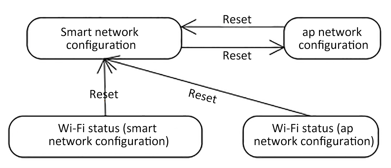
The module's self-processing WIFI reset method is: WIFI detects the GPIO entry low level for more than 5s to trigger Wi-Fi reset.
1. If the module working mode is set to "module self-processing", the MCU does not need to implement the protocol
MCU sends:
| Field | Length (byte) | Description |
| ------------ | ------------- | --------------------------------------------------------------- |
| Frame Header | 2 | 0x55aa |
| Version | 1 | 0x03 |
| Command Word | 1 | 0x04 |
| Data length | 2 | 0x0000 |
| Data | 0 | None |
| Checksum | 1 | Byte-sum results from the beginning of the frame, 256 remainder |
Example: 0x55aa 03 04 0000 06
The module returns:
| Field | Length (byte) | Description |
| ------------ | ------------- | --------------------------------------------------------------- |
| Frame Header | 2 | 0x55aa |
| Version | 1 | 0x00 |
| Command Word | 1 | 0x04 |
| Data length | 2 | 0x0000 |
| Data | 0 | None |
| Checksum | 1 | Byte-sum results from the beginning of the frame, 256 remainder |
Example: 0x55aa 00 04 0000 03
### 3.6、Reset WIFI-select configuration mode
Explanation:
1. Compared to “Resetting WIFI” in section 3.5, this frame provides the MCU to selectively choose the configuration mode after resetting WIFI according to its own needs.
2. MCU access users can selectively implement the protocol
3. If the module working mode is set to "module self-processing", the MCU does not need to implement the protocol
MCU sends:
| Field | Length (byte) | Description |
| ------------ | ------------- | -------------------------------------------------------------------------------------- |
| Frame Header | 2 | 0x55aa |
| Version | 1 | 0x03 |
| Command Word | 1 | 0x05 |
| Data length | 2 | 0x0001 |
| Data | 1 | 0x00: Enter smartconifg configuration mode
0x01: Enter AP configuration mode
|
| Checksum | 1 | Byte-sum results from the beginning of the frame, 256 remainder |
Example: 0x55aa 03 05 0001 00 08, enter smartconfig configuration mode
The module returns:
| Field | Length (byte) | Description |
| ------------ | ------------- | --------------------------------------------------------------- |
| Frame Header | 2 | 0x55aa |
| Version | 1 | 0x00 |
| Command Word | 1 | 0x05 |
| Data length | 2 | 0x0000 |
| Data | 0 | None |
| Checksum | 1 | Byte-sum results from the beginning of the frame, 256 remainder |
Example: 0x55aa 00 05 0000 04
### 3.7、Command issued
Explanation:
1. The datapoint command / status data unit is as follows:
| Data Section | Length (byte) | Explanation | | | |
| ------------ | ------------- | ----------------------------------------------------------------------------------------------------------------------------- | ----- | ----------------------------------- | -------------------------------------------------------------- |
| dpid | 1 | datapoint serial number | | | |
| type | 1 | Corresponds to the specific data type of a datapoint on the open platform, identified by the following "representation value" | | | |
| | | Type | Value | Length (bytes) | |
| | | raw | 0x00 | N | Corresponds to raw datapoint (module transparent transmission) |
| | | bool | 0x01 | 1 | value range: 0x00 / 0x01 |
| | value | 0x02 | 4 | Corresponds to int type, big-endian | |
| | | string | 0x03 | N | corresponds to a specific string |
| | | enum | 0x04 | 1 | Enumeration type, range 0-255 |
| | | bitmap | 0x05 | 1/2/4 | |
| len | 2 | Number of bytes corresponding to length | | | |
| value | 1/2/4 / N | hex indicates that big-endian transmission is used for more than 1 byte | | | |
1. Datapoint command / status data unit except "raw" type, other types are "obj" type datapoint
2. The "command delivery" may contain multiple datapoint "command data units"
3. "Command Issue" is an asynchronous processing protocol, corresponding to the "status report" of the MCU's datapoint
Module sends:
| Field | Length (byte) | Description |
| ------------ | ------------- | --------------------------------------------------------------- |
| Frame Header | 2 | 0x55aa |
| Version | 1 | 0x00 |
| Command Word | 1 | 0x06 |
| Data length | 2 | Depends on Command Data Unit type and number |
| Data | N | "3.7.1 Command Data Unit" Group |
| Checksum | 1 | Byte-sum results from the beginning of the frame, 256 remainder |
Example: The system switch corresponds to DP No. 3, using a bool-type variable, and the power-on value is 1.
0x55aa 00 06 0005 03 01 0001 01 10
### 3.8、Status report
Explanation:
1. For details of the datapoint status data unit, see "Section 3.7"
2. "State Report" is an asynchronous processing protocol. There are three types of "State Report" trigger mechanisms:
a. When the MCU receives the "command to issue a processing frame, the corresponding datapoint command is correctly executed, and then the changed datapoint status is sent to the module through the" status report "frame;
b. The MCU actively detects a change in the datapoint and sends the changed datapoint status to the module;
c. When the MCU receives the status query frame of “3.9”, it sends all datapoint status to the module.
3. The "status report" may contain multiple datapoint "command data units"
MCU sends:
| Field | Length (byte) | Description |
| ------------ | ------------- | --------------------------------------------------------------- |
| Frame Header | 2 | 0x55aa |
| Version | 1 | 0x03 |
| Command Word | 1 | 0x07 |
| Data length | 2 | Depends on the type and number of Status Data Units |
| Data | N | "3.7.1 Status Data Unit" Group |
| Checksum | 1 | Byte-sum results from the beginning of the frame, 256 remainder |
Example: The humidity corresponds to No. 5 DP, using a valve-type variable, and the humidity is 30 ° C
0x55aa 03 07 0008 05 02 0004 0000001e 3a
### 3.9、Status query
Explanation:
1. "Status query" is an asynchronous processing protocol, which is mainly used by the module to query the status of all "obj" type datapoints of the MCU. When the MCU receives this frame, it reports the datapoint status through the "3.8" status report frame
2. There are two main timings for sending "Status Query":
a. The module is powered on for the first time, and after the connection is established with the MCU through the heartbeat, the query is sent;
b. During the module's work, it is detected that the MCU restarts or goes offline and then goes online. The query is sent.
Module sends:
| Field | Length (byte) | Description |
| ------------ | ------------- | --------------------------------------------------------------- |
| Frame Header | 2 | 0x55aa |
| Version | 1 | 0x00 |
| Command Word | 1 | 0x08 |
| Data length | 2 | 0x0000 |
| Data | 0 | None |
| Checksum | 1 | Byte-sum results from the beginning of the frame, 256 remainder |
Example: 0x55aa 00 08 0000 07
### 3.10、MCU upgrade service
Explanation:
1. When to upgrade the customer The Tuya IoT platform ’s own product page configuration related upgrade options are triggered. The module is only used as a data transmission channel to support MCU upgrades and does not perform any analysis of the data content.
2. At present, the MCU upgrade of Tuya platform supports the following four configuration methods:
a.App reminder upgrade: In this upgrade method, users will receive the pop-up window of the upgrade reminder every time they enter the device control panel. Whether to confirm the upgrade is confirmed by the user in the App.
b.App silent upgrade: This upgrade method App will not have any pop-up window. The firmware will automatically detect the upgrade within one minute after the firmware is powered on. It will automatically start pulling related upgrade packages if it finds a higher version upgrade package. After power-on, the module will go to the cloud to check whether there is an upgrade package configuration at an interval of 24 hours.
c.App forced upgrade:In this upgrade method, there will be an upgrade reminder pop-up on the App side. If the user does not confirm the upgrade, the user cannot use the control panel of this product normally.
d.App detection upgrade: this upgrade method App sideThere will not be any pop-up window for upgrade reminder. The user must click on the App to check the relevant firmware version by himself. If there is a higher firmware configuration, the upgrade prompt message will be displayed.
3. MCU upgrade related flowchart:
After the WIFI module sends all the upgrade packages, resend the 01 command word (3.2 query product information). The MCU needs to reply the software version number in the product information with the updated MCU version number in one minute. The version number needs to be configured in Tuya's background. Upgraded version numbers remain the same.

**3.10.1、Upgrade started (upgrade package size notification)**
Explanation:
1. The upgrade startup method includes automatic and manual upgrades. When it is in automatic upgrade, the module detects that the cloud MCU has a newer version of firmware, then it automatically starts the interaction process with the MCU upgrade package; when it is in manual upgrade, it is determined by the App that the module inspires the interaction process with the MCU upgrade package
Module sends:
| Field | Length (byte) | Description |
| ------------ | ------------- | --------------------------------------------------------------- |
| Frame Header | 2 | 0x55aa |
| Version | 1 | 0x00 |
| Command Word | 1 | 0x0a |
| Data length | 2 | 0x0004 |
| Data | 4 | Firmware Package Bytes, unsigned int, Big Endian |
| Checksum | 1 | Byte-sum results from the beginning of the frame, 256 remainder |
Example: 0x55aa 00 0a 0004 00006800 75 (the firmware package length is 26624, which is 26KB)
The MCU returns:
| Field | Length (byte) | Description |
| ------------ | ------------- | --------------------------------------------------------------------------------------------------------------------------------- |
| Frame Header | 2 | 0x55aa |
| Version | 1 | 0x03 |
| Command Word | 1 | 0x0a |
| Data length | 2 | 0x0001 |
| Data | 1 | Upgrading packet transfer size:
0x00: default 256byte (compatible with old firmware)
0x01: 512byte
0x02: 1024byte
|
| Checksum | 1 | Byte-sum results from the beginning of the frame, 256 remainder |
Example: 0x55aa 03 0a 0001 00 0d
**3.10.2、Upgrade package transmission**
Explanation:
1. Upgrade packet transmission data format: packet offset (unsigned short) + packet data
2. If the MCU receives the frame data length of 4 and the packet offset > = firmware size, the packet transmission ends.
Module sends:
| Field | Length (byte) | Description |
| ------------ | ------------- | -------------------------------------------------------------------------------- |
| Frame Header | 2 | 0x55aa |
| Version | 1 | 0x00 |
| Command Word | 1 | 0x0b |
| Data length | 2 | 0x0004 + Data packet length |
| Data | N | The first four bytes, fixed at the packet offset, followed by the packet content |
| Checksum | 1 | Byte-sum results from the beginning of the frame, 256 remainder |
example:
The file size to be upgraded is 530Byte, (the last packet of data may not be returned)
(1) The first packet of data, the packet offset is 0x00000000, and the packet length is 256
0x55aa 00 0b 0104 00000000 xx ... xx XX
(2) The second packet of data, the packet offset is 0x00000100, and the packet length is 256
0x55aa 00 0b 0104 00000100 xx ... xx XX
(3) The third packet of data, the packet offset is 0x00000200, and the packet length is 18
0x55aa 00 0b 0016 00000200 xx ... xx XX
(4) The last packet, the packet offset is 0x00000212, and the data packet length is 0
0x55aa 00 0b 0004 00000212 xx ... xx XX
The MCU returns:
| Field | Length (byte) | Description |
| ------------ | ------------- | --------------------------------------------------------------- |
| Frame Header | 2 | 0x55aa |
| Version | 1 | 0x03 |
| Command Word | 1 | 0x0b |
| Data length | 2 | 0x0000 |
| Data | 0 | None |
| Checksum | 1 | Byte-sum results from the beginning of the frame, 256 remainder |
Example: 0x55aa 03 0b 0000 0d
### 3.11、Get System Time (GMT)
Explanation:
(1) Green Time does not include time zone and daylight saving time factors, and is an international standard time reference.
(2) When the local time stamp is calibrated before the module is connected to the network, it will return success with valid time data.
MCU sends:
| Field | Length (byte) | Description |
| ------------ | ------------- | --------------------------------------------------------------- |
| Frame Header | 2 | 0x55aa |
| Version | 1 | 0x03 |
| Command Word | 1 | 0x0c |
| Data length | 2 | 0x0000 |
| Data | 0 | None |
| Checksum | 1 | Byte-sum results from the beginning of the frame, 256 remainder |
Example: 0x55aa 03 0c 0000 0e
The module returns:
| Field | Length (byte) | Description |
| ------------ | ------------- | ----------------------------------------------------------------------------------------------------------------------------------------------------------------------------------------------------------------------------------------------------------------------------------------------------------------------------------------------------------------------------------------------------------------------- |
| Frame Header | 2 | 0x55aa |
| Version | 1 | 0x00 |
| Command Word | 1 | 0x0c |
| Data length | 2 | 0x0007 |
| Data | 7 | Data length is 7 bytes:
Data \[0] is the time success flag, 0 means failure, 1 means success
Data \[1] means year, 0x00 means 2000 Year
Data \[2] is the month, starting from 1 to 12
Data \[3] is the date, starting from 1 to 31
Data \[4] is the clock, starting from 0 to 23 ends
Data \[5] is minutes, starting from 0 to 59 and ends
Data \[6] is seconds, starting from 0 to 59 ends
|
| Checksum | 1 | Byte-sum results from the beginning of the frame, 256 remainder |
Example: 0x55aa 00 0c 0007 01 10 04 13 05 06 07 4c (5: 6: 7 GMT on April 19, 2016)
### 3.12、Get local time
Explanation:
(1) Local time is based on GMT plus local time (where the device is activated) and daylight saving time.
(2) When the local time stamp is calibrated before the module is connected to the network, it will return success with valid time data.
MCU sends:
| Field | Length (byte) | Description |
| ------------ | ------------- | --------------------------------------------------------------- |
| Frame Header | 2 | 0x55aa |
| Version | 1 | 0x03 |
| Command Word | 1 | 0x1c |
| Data length | 2 | 0x0000 |
| Data | xxxx | None |
| Checksum | 1 | Byte-sum results from the beginning of the frame, 256 remainder |
The module returns:
| Field | Length (byte) | Description |
| ------------ | ------------- | --------------------------------------------------------------------------------------------------------------------------------------------------------------------------------------------------------------------------------------------------------------------------------------------------------------------------------------------------------------------------------------------------------------------------------------------------------------------------------------- |
| Frame Header | 2 | 0x55aa |
| Version | 1 | 0x00 |
| Command Word | 1 | 0x1c |
| Data length | 2 | 0x0008 |
| Data | Data | The length of the data is 8 bytes:
Data \[0] is the time success flag, 0 means failure, 1 means success
Data \[1] means year, 0x00 means 2000 Year
Data \[2] is the month, starting from 1 to 12
Data \[3] is the date, starting from 1 to 31
Data \[4] is the clock, starting from 0 to 23 ends
Data \[5] is minutes, starts from 0 to 59 ends
Data \[6] is seconds, starts from 0 to 15 ends
Data \[7] is days, from 1 Start to end of 7, 1 for Monday
|
| Checksum | 1 | Byte-sum results from the beginning of the frame, 256 remainder |
example:
(1) If the device is activated and used in China, local time is Beijing time (Eastern District 8)
0x55aa 00 1c 0008 01 10 04 13 05 06 07 02 5f (Beijing time April 19, 2016 5: 6: 7PM)
(2) If the device is activated for use abroad, the local time is the time zone of the device
### 3.13、WIFI functional test (scan specified routes)
Explanation:
1. The module currently scans the specified SSID: tuya\_mdev\_test, and returns the scan result and signal strength percentage.
2. In order to prevent the defective products to the greatest extent, it is recommended that the customer control the distance between the router and the device to about 5 meters.
A signal strength of 60% or higher is qualified. Here you can adjust it according to your production line and factory environment.
MCU sends:
| Field | Length (byte) | Description |
| ------------ | ------------- | --------------------------------------------------------------- |
| Frame Header | 2 | 0x55aa |
| Version | 1 | 0x03 |
| Command Word | 1 | 0x0e |
| Data length | 2 | 0x0000 |
| Data | None | |
| Checksum | 1 | Byte-sum results from the beginning of the frame, 256 remainder |
The module returns:
| Field | Length (byte) | Description |
| ------------ | ------------- | ----------------------------------------------------------------------------------------------------------------------------------------------------------------------------------------------------------------------------------------------------------------------------------------------------------------------------------------------------------------------------------------------------------------------- |
| Frame Header | 2 | 0x55aa |
| Version | 1 | 0x00 |
| Command Word | 1 | 0x0e |
| Data Length | 2 | 0x0002 |
| Data | 2 | Data length is 2 bytes:
Data \[0]: 0x00 failed, 0x01 succeeded;
When Data \[0] is 0x01, that is, Data \[1] indicates the signal strength (0-100, 0 signal is the worst, 100 signal is the strongest)
When Data \[0] is 0x00, which means failure, Data \[1] is 0x00 means that the specified ssid is not scanned, and Data \[1] is 0x01 indicates that the module has not flashed the authorization key
|
| Checksum | 1 | Byte-sum results from the beginning of the frame, 256 remainder |
### 3.14、Get module memory
Description: Get the remaining memory of the WIFI module
MCU sends:
| Field | Length (byte) | Description |
| ------------ | ------------- | --------------------------------------------------------------- |
| Frame Header | 2 | 0x55aa |
| Version | 1 | 0x03 |
| Command Word | 1 | 0x0f |
| Data length | 2 | 0x0000 |
| Data | None | |
| Checksum | 1 | Byte-sum results from the beginning of the frame, 256 remainder |
The module returns:
| Field | Length (byte) | Description |
| ------------ | ------------- | ------------------------------------------------------------------------------------------------------------------------------- |
| Frame Header | 2 | 0x55aa |
| Version | 1 | 0x00 |
| Command Word | 1 | 0x0f |
| Data length | 2 | 0x0004 |
| Data | 4 | Data length is 4 bytes, big-endian format:
Such as 0x00 0x00 0x28 0x00 represents the remaining 10240 bytes of memory
|
| Checksum | 1 | Byte-sum results from the beginning of the frame, 256 remainder |
### 3.15、Turn on the function of obtaining weather data (optional)
Note: Turn on the function of obtaining weather data
MCU sends:
| Field | Length (byte) | Description |
| ------------ | ------------- | ---------------------------------------------------------------------------------------------------------------------------------------------------------------------------------------------- |
| Frame Header | 2 | 0x55aa |
| Version | 1 | 0x03 |
| Command Word | 1 | 0x20 |
| Data length | 2 | N ((L + K) + (L + K) ...) |
| Data | Data | L: Occupies 1 byte, indicating the length of K K: Request parameter name
For example: L: 0x06 K: w\.temp
L: 0x06 K: w\.pm25
L : 0x0a K: w\.humidity
L: 0x0b K: w\.condition
|
| Checksum | 1 | Byte-sum results from the beginning of the frame, 256 remainder |
The module returns:
| Field | length (byte) | Description |
| ------------ | ------------- | ----------- |
| Frame Header | 2 | 0x55aa |
| Version | 1 | 0x00 |
| Command Word | 1 | 0x20 |
| Data Length | 2 | 0x0002 |
Data | 2 | Data \[0]:\
0x00 indicates failure. For the specific error reason, see the error code description of Data \[1]\
0x01 indicates success\
Data \[1]: \
0x00 No error\
0x01 error code, illegal data format\
0x02 error code, abnormal error | Checksum | 1 | Byte-sum results from the beginning of the frame, 256 remainder |
### 3.16、Send weather data (optional)
Note: The weather data is issued. After the weather data function is turned on, the module will issue it regularly. After the function is turned on, it will be sent out immediately, followed by 30-minute intervals.
Module sends:
| Field | Length (byte) | Description |
| ------------ | ------------- | ---------------------------------------------------------------------------------------------------------------------------------------------------------------------------------------------------------------------------------------------------------------------------------------------------------------------------------------- |
| Frame Header | 2 | 0x55aa |
| Version | 1 | 0x00 |
| Command Word | 1 | 0x21 |
| Data length | 2 | N ((LKTLV) + (LKTLV) + ...) |
| Data | Data | 0x00: indicates failure
0x01: error code, indicates that the parameter service does not have permissions (confirm whether the parameter service is purchased)
0x01: indicates success
L: Parameter name length
K: Parameter name T: 0x00 integer, 0x01 character string
L: Field name length
V: Field value
|
| Checksum | 1 | Byte-sum results from the beginning of the frame, 256 remainder |
The MCU module returns:
| Field | Length (byte) | Description |
| ------------ | ------------- | --------------------------------------------------------------- |
| Frame Header | 2 | 0x55aa |
| Version | 1 | 0x00 |
| Command Word | 1 | 0x21 |
| Data length | 2 | 0x0000 |
| Data | 0 | None |
| Checksum | 1 | Byte-sum results from the beginning of the frame, 256 remainder |
Remarks:
1. The request parameter list such as w\.temp, w\.pm25 returns w\.temp, and the returned parameters are less than the request parameters. Please check carefully that the request parameter names are correct.
2. The field value of w\.condition can refer to "Weather UTF-8 Code Comparison Table" or the following "W\.condition Weather UTF-8 Code Table"
example:
w\.humidity: 69, w\.temp: 32, w\.pm25: 10, w\.condition: cloudy (UTF-8 encoding E5A49A E4BA91)
55 AA 00 21 00 40 01 0A 77 2E 68 75 6D 69 64 69 74 79 00 04 00 00 00 45 06 77 2E 74 65 6D 70 00 04 00 00 00 20 06 77 2E 70 6D 32 35 00 04 00 00 00 10 0B 77 2E 63 6F 6E 64 69 74 69 6F 6E 01 06 E5 A4 9A E4 BA 91 1E
The weather UTF-8 code table for w\.condition is as follows:
| Text | hex encoding | text | hex encoding |
| ---------------------- | ------------------------------------------------ | -------------------- | --------------------------- |
| Sunny | E699B4 | Heavy Rain | E5A4A7 E99BA8 |
| Thunderstorm | E99BB7 E69AB4 | Sandstorm | E6B299 E5B098 E69AB4 |
| Light Snow | E5B08F E99BAA | Snow | E99BAA |
| Frost Mist | E586BB E99BBE | Heavy Rain | E69AB4 E99BA8 |
| Partial showers | E5B180 E983A8 E998B5 E99BA8 | Dust | E6B5AE E5B098 |
| Lightning | E99BB7 E794B5 | Light Shower | E5B08F E998B5 E99BA8 |
| Rain | E99BA8 | Sleet | E99BA8 E5A4B9 E99BAA |
| Dust tornado | E5B098 E58DB7 E9A38E | Ice particles | E586B0 E7B292 |
| Strong Sandstorm | E5BCBA E6B299 E5B098 E69AB4 | Yangsha | E689AC E6B299 |
| Light to moderate rain | E5B08F E588B0 E4B8AD E99BA8 | Mostly sunny | E5A4A7 E983A8 E699B4 E69C97 |
| Fog | E99BBE | Shower | E998B5 E99BA8 |
| Strong showers | E5BCBA E998B5 E99BA8 | Heavy Snow | E5A4A7 E99BAA |
| Heavy Rain | E789B9 E5A4A7 E69AB4 E99BA8 | Blizzard | E69AB4 E99BAA |
| Hail | E586B0 E99BB9 | Small to medium snow | E5B08F E588B0 E4B8AD E99BAA |
| Shao Yun | E5B091 E4BA91 | Snow showers | E5B08F E998B5 E99BAA |
| Zhongxue | E4B8AD E99BAA | Overcast | E998B4 |
| Ice Needle | E586B0 E99288 | Heavy Rain | E5A4A7 E69AB4 E99BA8 |
| Thunderstorm with hail | E99BB7 E998B5 E99BA8 E4BCB4 E69C89 E586B0 E99BB9 | Freezing rain | E586BB E99BA8 |
| Snow showers | E998B5 E99BAA | Light rain | E5B08F E99BA8 |
| Haze | E99CBE | Rain | E4B8AD E99BA8 |
| Cloudy | E5A49A E4BA91 | Thunderstorm | E99BB7 E998B5 E99BA8 |
| Medium to heavy rain | E4B8AD E588B0 E5A4A7 E99BA8 | Heavy rain | E5A4A7 E588B0 E69AB4 E99BA8 |
### 3.17、Status reporting (synchronous)
Explanation:
1. This command is a synchronous instruction. After the MCU data status is reported, you need to wait for the module to return the result.
2. Each time the sending module will respond, the WIFI module cannot report multiple times before it responds;
3. When the network is not good and the data is difficult to report in time, the module will fail after 5 and the MCU will need to wait more than 5 seconds.
4. For details of the datapoint status data unit, see "Section 3.7"
5. The "status report" may contain multiple datapoint "command data units"
MCU sends:
| Field | Length (byte) | Description |
| ------------ | ------------- | --------------------------------------------------------------- |
| Frame Header | 2 | 0x55aa |
| Version | 1 | 0x03 |
| Command Word | 1 | 0x22 |
| Data length | 2 | Depends on the type and number of Status Data Units |
| Data | N | "3.7.1 Status Data Unit" Group |
| Checksum | 1 | Byte-sum results from the beginning of the frame, 256 remainder |
The module returns:
| Field | Length (byte) | Description |
| ------------ | ------------- | --------------------------------------------------------------- |
| Frame Header | 2 | 0x55aa |
| Version | 1 | 0x00 |
| Command Word | 1 | 0x23 |
| Data Length | 2 | 0x01 |
| Data | Data | 0x00: indicates failure
0x01: indicates success
|
| Checksum | 1 | Byte-sum results from the beginning of the frame, 256 remainder |
### 3.18、Get the current WIFI signal strength (optional)
MCU sends:
| Field | Length (byte) | Description |
| ------------ | ------------- | --------------------------------------------------------------- |
| Frame Header | 2 | 0x55aa |
| Version | 1 | 0x03 |
| Command Word | 1 | 0x24 |
| Data length | 2 | 0 |
| Data | N | None |
| Checksum | 1 | Byte-sum results from the beginning of the frame, 256 remainder |
The module returns:
| Field | Length (byte) | Description |
| ------------ | ------------- | ----------------------------------------------------------------------------------------- |
| Frame Header | 2 | 0x55aa |
| Version | 1 | 0x00 |
| Command Word | 1 | 0x24 |
| Data length | 2 | 0x0001 |
| Data | Data | 0x00: indicates failure
less than 0: indicates signal strength, such as (-60db)
|
| Checksum | 1 | Byte-sum results from the beginning of the frame, 256 remainder |
### 3.19、Notify WIFI module to turn off heartbeat (optional)
MCU sends:
| Field | Length (byte) | Description |
| ------------ | ------------- | --------------------------------------------------------------- |
| Frame Header | 2 | 0x55aa |
| Version | 1 | 0x03 |
| Command Word | 1 | 0x25 |
| Data length | 2 | 0 |
| Data | N | None |
| Checksum | 1 | Byte-sum results from the beginning of the frame, 256 remainder |
The module returns:
| Field | Length (byte) | Description |
| ------------ | ------------- | --------------------------------------------------------------- |
| Frame Header | 2 | 0x55aa |
| Version | 1 | 0x00 |
| Command Word | 1 | 0x25 |
| Data length | 2 | 0 |
| Data | N | None |
| Checksum | 1 | Byte-sum results from the beginning of the frame, 256 remainder |
Explanation:
For MCU modules that need to sleep to reduce power consumption, this command can be sent before sleep to turn off the heartbeat of the WIFI module, which is convenient for entering the sleep state. Do not send this command when the device is powered on. After the WIFI module is powered on, a heartbeat connection must be established with the MCU.
### 3.20、Serial port network interface (optional)
Explanation:
1. It can be used for Tuya App or Tuya App's SDK for independent development to obtain relevant distribution network parameters, and can send serial data to the module through the serial port to achieve the module's network distribution operation through serial communication.
2. The module must be in the network ready state to complete serial port network configuration.
3. After the module returns the response of successfully receiving the serial network configuration information, it will use the received information to connect to the route and activate it in the cloud.
MCU sends:
| Field | Length (byte) | Description |
| ------------ | ------------- | --------------------------------------------------------------------------------------- |
| Frame Header | 2 | 0x55aa |
| Version | 1 | 0x03 |
| Command Word | 1 | 0x2A |
| Data length | 2 | xx |
| Data | Data | {"s": "xxx", "p": "yyy", "t": "zzz"} s: ssid p: password t: token, generated by the App |
| Checksum | 1 | Byte-sum results from the beginning of the frame, 256 remainder |
The module returns:
| Field | Length (byte) | Description |
| ------------ | ------------- | ------------------------------------------------------------------------------------------------------------------------------ |
| Frame Header | 2 | 0x55aa |
| Version | 1 | 0x00 |
| Command Word | 1 | 0x2A |
| Data Length | 2 | 0x0001 |
| Data | x | 0x00: Data received successfully
0x01: Not in the network status
0x02: json data is illegal
0x03: Other errors
|
| Checksum | 1 | Byte-sum results from the beginning of the frame, 256 remainder |
### 3.21、Get the current WIFI network status
| Device Networking Status | Description | Status Values |
| ------------------------ | -------------------------------------------------- | ------------- |
| Status 1 | smartconfig configuration status | 0x00 |
| State 2 | AP configuration state | 0x01 |
| State 3 | WIFI is configured but not connected to the router | 0x02 |
| State 4 | WIFI is configured and connected to the router | 0x03 |
| Status 5 | Connected to the router and connected to the cloud | 0x04 |
| State 6 | WIFI device is in low power mode | 0x05 |
| State 7 | WIFI device is in smartconfig\&AP mode | 0x06 |
Note: Consistent with 3.4.
MCU sends:
| Field | Length (byte) | Description |
| ------------ | ------------- | --------------------------------------------------------------- |
| Frame Header | 2 | 0x55aa |
| Version | 1 | 0x03 |
| Command Word | 1 | 0x2B |
| Data length | 2 | 0x0000 |
| Data | None | |
| Checksum | 1 | Byte-sum results from the beginning of the frame, 256 remainder |
The module returns:
| Field | Length (byte) | Description |
| ------------ | ------------- | ---------------------------------------------------------------------------------------------------------------------------------------------------------------------------------------------------------------------------------------------------------------------------------------------------------------------------------------------------- |
| Frame Header | 2 | 0x55aa |
| Version | 1 | 0x00 |
| Command Word | 1 | 0x2B |
| Data length | 2 | 0x0000 |
| Data | x | 0x00: smartconfig configuration status
0x01: AP configuration status
0x02: WIFI is configured but not connected to a router
0x03: WIFI is configured and connected to a router
0x04: Connected to the router and connected to the cloud
0x05: WIFI device is in low power mode
0x06: WIFI device is in smartconfig\&AP mode
|
| Checksum | 1 | Byte-sum results from the beginning of the frame, 256 remainder |
### 3.22、Sweeper map data service (optional)
Explanation:
1. The command of the sweeper stream service is not supported by all modules. The use of this service requires the use of a specific module to enable related services before it can be used normally.
2. This service is currently a service for the transmission of the map data of the sweeper, as a special shortcut channel for the sweeper and Tuya App map line.
3. The complete map data of the sweeper is distinguished by the map ID in the protocol. The data App of the same ID will think that this is a map data and will be accumulated.
4. The sweeping machine needs to move around the whole house during the cleaning process. Here, weak WIFI signals in some areas may cause data upload failure. At present, the module can cache 24 pieces of data under sufficient premise.

#### **3.22.1、Map Stream Data Transmission**
Explanation:
1\) The offset indicates the total length of data that has been sent before the map data MCU.
2\) The data content here can be up to 1024 bytes in the module serial port.
The data part of the data packet cannot exceed 1024 bytes, and the content of map data in each packet is recommended to be 512 bytes per packet.
3\) The map ID is used as a sign of a complete map data. The data transmission party needs to change the map ID to start a new cleaning after the completion of a completed cleaning, that is, the end of a map data. Generally, the map ID is performed in increments. Display local map ID. Changing the current map data display will clear the previous data and restart the display.
4\) After the data transmission is started, the module will stop sending heartbeat packets to ensure the priority transmission of map data. The subsequent modules will not actively resume the sending of heartbeat packets under the premise of continuous power.
MCU sends:
| Field | Length (byte) | Description |
| ------------ | ------------- | ----------------------------------------------------------------------------------- |
| Frame Header | 2 | 0x55aa |
| Version | 1 | 0x03 |
| Command Word | 1 | 0x28 |
| Data length | 2 | 0x0006 + N |
| Data | 2 | Map ID number: The map ID number is used as the belonging identifier of a map data. |
| | 4 | Offset (the first packet is 0) |
| | N | Entity Data (Big Endian Mode) |
| Checksum | 1 | Byte-sum results from the beginning of the frame, 256 remainder |
The module returns:
| Field | Length (byte) | Description |
| ------------ | ------------- | ------------------------------------------------------------------------------------------------------------------------------------------------------------------------------------------------------------------------ |
| Frame Header | 2 | 0x55aa |
| Version | 1 | 0x00 |
| Command Word | 1 | 0x28 |
| Data length | 2 | 0x0001 |
| Data | Data | 0x00: Success
0x01: The streaming service function is not enabled
0x02: The streaming server was not successfully connected
0x03: Data push timeout
0x04: The length of the transmitted data is wrong
|
| Checksum | 1 | Byte-sum results from the beginning of the frame, 256 remainder |
### 3.23、WIFI functional test (connection specified route)
Explanation:
1. After the MCU sends the routing information to the module successfully, the module will use the relevant information to connect to the route.
2. The MCU here determines whether to connect to the router, according to the packet received in the module 3.4 protocol (state 4-WIFI is configured and connected to the router). Here it is judged that the failed MCU receives the return failure, or does not receive the status packet connected to the route for a long time (more than 15S) and considers it to have failed.
3. The production test can be re-sent to the production test and the test command can be resent. If no routing packet is received, it indicates that the module is in production test and needs to reset the module or send the test command to power on again.
4. The module needs to be connected to the network to complete the connection test.
5. Before the production test, the module's heartbeat package and product query package module must be initialized before entering the production test of the connection route.
6. The router name string length supports a maximum of 32 bytes, and the router password string length supports a maximum of 64 bytes.
MCU sends:
| Field | Length (byte) | Description |
| ------------ | ------------- | ----------------------------------------------------------------------------------- |
| Frame Header | 2 | 0x55aa |
| Version | 1 | 0x03 |
| Command Word | 1 | 0x2C |
| Data Length | 2 | xxxx |
| Data | Data | {"ssid": "xxx", "password": "xxxxxxxx"} ssid: route name password: routing password |
| Checksum | 1 | Byte-sum results from the beginning of the frame, 256 remainder |
The module returns:
| Field | Length (byte) | Description |
| ------------ | ------------- | ---------------------------------------------------------------------------------------------------------------------------------------------------------------------------------------------------------------------------------------------------------------------------------------------------------- |
| Frame Header | 2 | 0x55aa |
| Version | 1 | 0x00 |
| Command Word | 1 | 0x2C |
| Data length | 2 | 0x0001 |
| Data | 1 | The data length is 1 byte:
Data \[0]:
0x00 routing information reception failed:
(Please check whether the routing information packet sent is not the completed JSON packet data )
0x01 routing information received successfully (result please note the network status packet in 3.4)
|
| Checksum | 1 | Byte-sum results from the beginning of the frame, 256 remainder |
### 3.24、Get module MAC
MCU sends:
| Field | Length (byte) | Description |
| ------------ | ------------- | --------------------------------------------------------------- |
| Frame Header | 2 | 0x55aa |
| Version | 1 | 0x03 |
| Command Word | 1 | 0x2d |
| Data length | 2 | 0x0000 |
| Data | None | |
| Checksum | 1 | Byte-sum results from the beginning of the frame, 256 remainder |
The module returns:
| Field | Length (byte) | Description |
| ------------ | -------------------------------------------------------------------------------------------------------------------------------------------------------------------------------------------------------------------------------------------------------------------------------------------------------------------------------------------------------------------------------------------------------------------------------------- | --------------------------------------------------------------- |
| Frame Header | 2 | 0x55aa |
| Version | 1 | 0x00 |
| Command Word | 1 | 0x2d |
| Data length | 2 | 0x0007 |
| Data | data \[0]:
Flag indicating whether the MAC address was successfully obtained:
0x00 indicates success, which means that the next 6 bytes of the MAC address are valid.
0x01 indicates that the MAC address failed, Indicates that the following 6 bytes of the MAC are invalid.
data \[1] \ \~ data \[6]: When the MAC address flag data \[0] is obtained, it indicates that the module has a valid MAC address.
| |
| Checksum | 1 | Byte-sum results from the beginning of the frame, 256 remainder |
### 3.25、Infrared status notification (optional)
| Device Infrared Status | Description | Status Value |
| ---------------------- | ------------------------ | ------------ |
| Status 1 | Sending Infrared Code | 0x00 |
| State 2 | Send infrared code end | 0x01 |
| State 3 | Infrared Learning Begins | 0x02 |
| State 4 | Infrared Learning End | 0x03 |
Explanation:
1. The infrared function is manually configured and sent samples by the Tuya IOT front desk configuration or the relevant project manager.
2. The time period of infrared code sending is very short and needs to maintain good real-time performance. Here the serial data is sent directly. No related retransmissions are performed.
3. According to their own development needs, customers can display related status according to the infrared status report.
4. Infrared code sending and receiving infrared codes need to use the two IO pins of the module. If the networking status of your device is also the module's self-processing mode, please note that the IO port should not be set with related IO pins.
Module sends:
| Field | Length (byte) | Description |
| ------------ | ------------- | ---------------------------------------------------------------------------------------------------------------- |
| Frame Header | 2 | 0x55aa |
| Version | 1 | 0x00 |
| Command Word | 1 | 0x2e |
| Data length | 2 | 0x0001 |
| Data | Data | Indicate infrared working status:
0x00: status 1
0x01: status 2
0x02: status 3
0x03: status 4
|
| Checksum | 1 | Byte-sum results from the beginning of the frame, 256 remainder |
MCU returns:
| Field | Length (byte) | Description |
| ------------ | ------------- | --------------------------------------------------------------- |
| Frame Header | 2 | 0x55aa |
| Version | 1 | 0x03 |
| Command Word | 1 | 0x2e |
| Data length | 2 | 0x0000 |
| Data | None | |
| Checksum | 1 | Byte-sum results from the beginning of the frame, 256 remainder |
### 3.26、Infrared enters production test (optional)

Explanation:
1. The infrared production test function can be entered only when the network is not configured.
2. The module enters the infrared learning state when it enters the infrared production test state.
3. Once the module enters the infrared production test mode, it will always be in the production test state and then send it out according to the learning data. When the module is equipped with the Internet or is powered off, it will exit the production test.
MCU sends:
| Field | Length (byte) | Description |
| ------------ | ------------- | --------------------------------------------------------------- |
| Frame Header | 2 | 0x55aa |
| Version | 1 | 0x03 |
| Command Word | 1 | 0x2f |
| Data length | 2 | 0x0000 |
| Data | None | |
| Checksum | 1 | Byte-sum results from the beginning of the frame, 256 remainder |
The module returns:
| Field | Length (byte) | Description |
| ------------ | ------------- | ------------------------------------------------------------------------------------------------------------------------------------------------------------------------------------------ |
| Frame Header | 2 | 0x55aa |
| Version | 1 | 0x00 |
| Command Word | 1 | 0x2f |
| Data length | 2 | 0x0001 |
| Data | Data | 0x00 indicates that the infrared transmission and reception production testing was successful
0x01 indicates that the infrared transmission and reception production test failed
|
| Checksum | 1 | Byte-sum results from the beginning of the frame, 256 remainder |
### 3.27、Map streaming data transmission (supports multiple map data) (optional)
Explanation: 1) The commands of the sweeping machine streaming service are not supported by all modules. To use this service, you need to use a specific module to activate related services before it can be used normally. 2) This service is currently aimed at the data transmission of sweeper maps, and serves as a special shortcut for sweeper and graffiti APP map lines. 3) This channel is used for sweeping a map to show a sweeper machine with multiple data maps synthesized.
MCU sends:
| Field | Length (byte) | Description |
| ------------ | ------------- | ----------------------------------------------------------------------------------------------------------------------------------------------------------------------------------------------------------------------------------------------------------------------------------------------------------------- |
| Frame Header | 2 | 0x55aa |
| Version | 1 | 0x03 |
| Command Word | 1 | 0x30 |
| Data length | 2 | 0x0009+N |
| Data | 1 | Map service agreement version: 0x00 |
| | 2 | Map service session ID number: used as a sign for a map display |
| | 6 | BUF \[0] Sub-map ID number (a map session can be synthesized from multiple map data, such as a route map)
BUF \[1] Map ID data processing method 0x00: continue to accumulate 0x01: clear the data uploaded by the sub map ID number
BUF \[2] \~ BUF \[5] Submap data offset (the first packet is 0)
|
| | N | Entity data (big endian mode) |
| Checksum | 1 | Byte-sum results from the beginning of the frame, 256 remainder |
The module returns:
| Field | Length (byte) | Description |
| ------------ | ------------- | --------------------------------------------------------------- |
| Frame Header | 2 | 0x55aa |
| Version | 1 | 0x00 |
| Command Word | 1 | 0x30 |
| Data length | 2 | 0x0001 |
| Data | 1 | 0x00:success
0x01:failure
|
| Checksum | 1 | Byte-sum results from the beginning of the frame, 256 remainder |
### 3.28、File download service (optional)
Description: 1) This channel is used by customers to download and use application files other than MCU firmware. The files need to be uploaded to the Tuya product management background to be used with the corresponding version APP. 2) The firmware only performs the data transmission channel and does not do anything to the customer to download the file. The integrity check in the relevant file is handled by the user. 3) While the file is being downloaded, DP data can also be sent and uploaded normally. It is not recommended to do large amount of data communication during file download to affect the data download efficiency.
**3.28.1、Download start (file package size notification)**
Description: 1) Before the actual file is downloaded here, the module will first send the size of the file to be downloaded to the MCU as the download start notification. When the MCU confirms that the length of the packet is correct, it will start to pull the file package when the command packet is returned normally Otherwise, the process of pulling files will be interrupted and exited.
Module send:
| Field | Length (byte) | Description |
| ------------ | ------------- | --------------------------------------------------------------- |
| Frame Header | 2 | 0x55aa |
| Version | 1 | 0x00 |
| Command Word | 1 | 0x31 |
| Data length | 2 | 0x0004 |
| Data | 4 | File total bytes, unsigned int, big endian |
| Checksum | 1 | Byte-sum results from the beginning of the frame, 256 remainder |
Example: 0x55aa 00 31 0004 00006800 9C (file length 26624, or 26KB)
The MCU returns:
| Field | Length (byte) | Description |
| ------------ | ------------- | --------------------------------------------------------------- |
| Frame Header | 2 | 0x55aa |
| Version | 1 | 0x03 |
| Command Word | 1 | 0x31 |
| Data length | 2 | 0x0001 |
| Data | 4 | File transfer size:0x00:256byte0x01:512byte0x02:1024byte |
| Checksum | 1 | Byte-sum results from the beginning of the frame, 256 remainder |
Example:0x55aa 03 31 0001 00 34
**3.28.2、File package transfer**
Description: 1) Upgrade package transmission data format: package offset (unsigned short) + package data 2) If the MCU receives the data length of the frame is 4 and the packet offset> = firmware size, the packet transmission ends
Description: 1) Upgrade package transmission data format: package offset (unsigned short) + package data 2) If the MCU receives the data length of the frame is 4 and the packet offset >= firmware size, the packet transmission ends
Module send:
| Field | Length (byte) | Description |
| ------------ | ------------- | ---------------------------------------------------------------------------------------- |
| Frame Header | 2 | 0x55aa |
| Version | 1 | 0x00 |
| Command Word | 1 | 0x32 |
| Data length | 2 | 0x0004 + Packet length |
| Data | 4 | The first four bytes are fixed to the packet offset, followed by the data packet content |
| Checksum | 1 | Byte-sum results from the beginning of the frame, 256 remainder |
example:
The file size to be upgraded is 530Byte, (the last packet of data may not be returned)
(1) The first packet of data, the packet offset is 0x00000000, and the packet length is 256
0x55aa 00 32 0104 00000000 xx… xx XX
(2) The second packet data, the packet offset is 0x00000100, and the data packet length is 256
0x55aa 00 32 0104 00000100 xx… xx XX
(3) The third packet of data, the packet offset is 0x00000200, and the packet length is 18
0x55aa 00 32 0016 00000200 xx… xx XX
(4) The last packet, the packet offset is 0x00000212, and the data packet length is 0
0x55aa 00 32 0004 00000212 xx ... xx XX
The MCU returns:
| Field | Length (byte) | Description |
| ------------ | ------------- | --------------------------------------------------------------- |
| Frame Header | 2 | 0x55aa |
| Version | 1 | 0x03 |
| Command Word | 1 | 0x32 |
| Data length | 2 | 0x0000 |
| Data | 0 | |
| Checksum | 1 | Byte-sum results from the beginning of the frame, 256 remainder |
Example:0x55aa 03 32 0000 34
### 3.29、Voice module related protocol (optional)
Description: 1) The protocols in this catalog apply to the universal docking of the voice module VWXR2 2) The general firmware of other non-voice modules does not have the relevant protocol functions in this directory
**3.29.1、Get voice status code (optional)**
Description:
1. The voice status code of the voice module will automatically return, and the MCU can also actively query.
MCU sends:
| Field | Length (byte) | Description |
| ------------ | ------------- | --------------------------------------------------------------- |
| Frame Header | 2 | 0x55aa |
| Version | 1 | 0x03 |
| Command Word | 1 | 0x60 |
| Data length | 2 | 0x0000 |
| Data | 0 | |
| Checksum | 1 | Byte-sum results from the beginning of the frame, 256 remainder |
The module returns:
| Field | Length (byte) | Description |
| ------------ | ------------- | -------------------------------------------------------------------------------------------------------------------------------------------------------------------- |
| Frame Header | 2 | 0x55aa |
| Version | 1 | 0x00 |
| Command Word | 1 | 0x60 |
| Data length | 2 | 0x0001 |
| Data | 1 | Voice status code:
0: idle;
1: mic mute state;
2: wake up;
3: recording;
4: recognition;
5: Recognition success;
6: Recognition failure;
|
| Checksum | 1 | Byte-sum results from the beginning of the frame, 256 remainder |
**3.29.2、mic mute setting (optional)**
Description:
1. The command word can be set to mute, or query the mute state.
MCU sends:
| Field | Length (byte) | Description |
| ------------ | ------------- | ------------------------------------------------------------------------------------------ |
| Frame Header | 2 | 0x55aa |
| Version | 1 | 0x03 |
| Command Word | 1 | 0x61 |
| Data length | 2 | 0x0001 |
| Data | 1 | Mute setting value:
0x00: mic on;
0x01: mic mute;
0xA0: query mute status;
|
| Checksum | 1 | Byte-sum results from the beginning of the frame, 256 remainder |
The module returns:
| Field | Length (byte) | Description |
| ------------ | ------------- | --------------------------------------------------------------- |
| Frame Header | 2 | 0x55aa |
| Version | 1 | 0x00 |
| Command Word | 1 | 0x61 |
| Data length | 2 | 0x0001 |
| Data | 1 | Mute state value:
0: mic is on;
1: mic is mute;
|
| Checksum | 1 | Byte-sum results from the beginning of the frame, 256 remainder |
**3.29.3、Speaker volume setting (optional)**
Description:
1. The command word can set the volume, and also can query the volume.
MCU sends:
| Field | Length (byte) | Description |
| ------------ | ------------- | --------------------------------------------------------------- |
| Frame Header | 2 | 0x55aa |
| Version | 1 | 0x03 |
| Command Word | 1 | 0x62 |
| Data length | 2 | 0x0001 |
| Data | 1 | 0-10:Volume value;
0xA0:query volume;
|
| Checksum | 1 | Byte-sum results from the beginning of the frame, 256 remainder |
The module returns:
| Field | Length (byte) | Description |
| ------------ | ------------- | --------------------------------------------------------------- |
| Frame Header | 2 | 0x55aa |
| Version | 1 | 0x00 |
| Command Word | 1 | 0x62 |
| Data length | 2 | 0x0001 |
| Data | 1 | 0-10:Volume value; |
| Checksum | 1 | Byte-sum results from the beginning of the frame, 256 remainder |
**3.29.4、Audio production test (optional)**
Description:
1. Audio production test is to record and broadcast while comparing the input and output audio signals of the module through acoustic instruments.
MCU sends:
| Field | Length (byte) | Description |
| ------------ | ------------- | ------------------------------------------------------------------------------------------------------------------------------------------------------------------------------------------------- |
| Frame Header | 2 | 0x55aa |
| Version | 1 | 0x03 |
| Command Word | 1 | 0x63 |
| Data length | 2 | 0x0001 |
| Data | 1 | Audio production test value:
0x00: turn off the audio production test;
0x01: mic1 audio loop test;
0x02: mic2 audio loop test;
0xA0: query the current production test status;
|
| Checksum | 1 | Byte-sum results from the beginning of the frame, 256 remainder |
The module returns:
| Field | Length (byte) | Description |
| ------------ | ------------- | --------------------------------------------------------------- |
| Frame Header | 2 | 0x55aa |
| Version | 1 | 0x00 |
| Command Word | 1 | 0x63 |
| Data length | 2 | 0x0001 |
| Data | 1 | Current production value |
| Checksum | 1 | Byte-sum results from the beginning of the frame, 256 remainder |
**3.29.5、Wake up production test (optional)**
Description:
1. After entering the wake-up test, it is required to play the wake-up word electrical signal for 10s, and return failure after 10s timeout.
MCU sends:
| Field | Length (byte) | Description |
| ------------ | ------------- | --------------------------------------------------------------- |
| Frame Header | 2 | 0x55aa |
| Version | 1 | 0x03 |
| Command Word | 1 | 0x64 |
| Data length | 2 | 0x0000 |
| Data | 0 | |
| Checksum | 1 | Byte-sum results from the beginning of the frame, 256 remainder |
The module returns:
| Field | Length (byte) | Description |
| ------------ | ------------- | -------------------------------------------------------------------------- |
| Frame Header | 2 | 0x55aa |
| Version | 1 | 0x00 |
| Command Word | 1 | 0x64 |
| Data length | 2 | 0x0001 |
| Data | 1 | Wake-up result returns
0: Wake-up failed;
1: Wake-up success;
|
| Checksum | 1 | Byte-sum results from the beginning of the frame, 256 remainder |
**3.29.6、extensions**
Description: Expand the relevant system functions of the voice module
1\) Add status notification and settings for "Play/Pause, Bluetooth On/Off, Local Alarm, Voice Control Combination" function
"Play/Pause" function: play and pause functions of music, ancient poems, jokes, etc.;
"Bluetooth on/off" function: Bluetooth switch of Bluetooth speaker;
"Local alarm clock" function: synchronous notification of alarm data set by voice and APP;
"Voice control combination" function: notification of voice control instructions such as "previous song" and "next song";
**MCU function settings:**
MCU sends:
| Field | Length (byte) | Description |
| ------------ | --------------------------------------------- | --------------------------------------------------------------------------------------------------------------------------------------------------------------------------------------- |
| Frame Header | 2 | 0x55aa |
| Version | 1 | 0x03 |
| Command Word | 1 | 0x65 |
| Data length | 2 | N |
| Data | 1 | Subcommand:0x00 |
| | Data:
{“play”:true,”bt\_play”:true}
| play: play/pause function
true (play)/false (pause)
bt\_play: Bluetooth switch function true (on)/false(off)
MCU settings only support "play/pause" ""Bluetooth switch"
|
| Checksum | 1 | Byte-sum results from the beginning of the frame, 256 remainder |
Module returns:
| Field | Length (byte) | Description |
| ------------ | ------------- | --------------------------------------------------------------- |
| Frame Header | 2 | 0x55aa |
| Version | 1 | 0x00 |
| Command Word | 1 | 0x65 |
| Data length | 2 | 0x0002 |
| Data | 1 | Subcommand:0x00 |
| | 1 | Operation result:
0x00: success
0x01: failure
|
| Checksum | 1 | Byte-sum results from the beginning of the frame, 256 remainder |
**Status notification:**
Module sends:
| Field | Length (byte) | Description |
| ------------ | ----------------------------------------------------------------------------------- | ----------------------------------------------------------------------------------------------------------------------------------------------------------------------------------------------------------------------------------------------------------------------------- |
| Frame Header | 2 | 0x55aa |
| Version | 1 | 0x00 |
| Command Word | 1 | 0x65 |
| Data length | 2 | 1+N |
| Data | 1 | Subcommand:0x01 |
| | Data:
{“play”:true,”bt\_play”:true,” alarm”:”xxxx”,” ctrl\_group”:”xxxx”}
| play: play/pause function
true(play)/false(pause)
bt\_play: Bluetooth switch function
true(on)/false(off)
alarm: local alarm function
"xxx" is a character string
ctrl\_group: voice control combination function
"xxx" is a character string
|
| Checksum | 1 | Byte-sum results from the beginning of the frame, 256 remainder |
MCU returns:
| Field | Length (byte) | Description |
| ------------ | ------------- | --------------------------------------------------------------- |
| Frame Header | 2 | 0x55aa |
| Version | 1 | 0x03 |
| Command Word | 1 | 0x65 |
| Data length | 2 | 0x0002 |
| Data | 1 | Subcommand:0x01 |
| | 1 | Operation result:
0x00: success
0x01: failure
|
| Checksum | 1 | Byte-sum results from the beginning of the frame, 256 remainder |
#### 3.30、Module development service
**3.30.1、Turn on module time service notification**
Description:
1\) The MCU requires the module to re-power on every time to notify the MCU whether the time of the module has been calibrated in the cloud. Use this command to open the module's initiative to notify the MCU of the time data service required.
2\) After the module is powered on, the service is started. When the time is calibrated, the time service required by the MCU to actively notify the relevant time is selected, and the time data required by the relevant MCU is sent.
3\) If the module is not powered on, the service will not be restarted after the service is turned on. If the module is not restarted, you need to obtain the time and time.
4\) At present, the acquisition time protocol of 3.11 and 3.12, the time stamp of the module will not be calibrated immediately after connecting to the server. There is a time period that causes the MCU to retry to obtain the time every time it is powered on. This service can be activated after the module Proactively notify the MCU after time calibration
MCU sends:
| Field | Length (byte) | Description |
| ------------ | ------------- | --------------------------------------------------------------- |
| Frame Header | 2 | 0x55aa |
| Version | 1 | 0x03 |
| Command Word | 1 | 0x34 |
| Data length | 2 | 0x0002 |
| Data | 1 | 0x01 (subcommand) |
| | 1 | 0x00: Green time
0x01: Local time
|
| Checksum | 1 | Byte-sum results from the beginning of the frame, 256 remainder |
The module returns:
| Field | Length (byte) | Description |
| ------------ | ------------- | ------------------------------------------------------------------------- |
| Frame Header | 2 | 0x55aa |
| Version | 1 | 0x00 |
| Command Word | 1 | 0x34 |
| Data length | 2 | 0x0002 |
| Data | 1 | 0x01 (subcommand) |
| | 1 | 0x00: Service started successfully
0x01: Service started failed
|
| Checksum | 1 | Byte-sum results from the beginning of the frame, 256 remainder |
**3.30.2、Module Time Service Notification**
Description:
1\) The module chooses to send the corresponding time data according to the service of the open time notification sent by the MCU.
2\) The module power-on service is closed, and the MCU needs to re-send the open module time notification service
Module sends:
| Field | Length (byte) | Description |
| ------------ | ------------- | ------------------------------------------------------------------------------------------------------------------------------------------------------------------------------------------------------------------------------------------------------------------------------------------------------------------------------------------------------ |
| Frame Header | 2 | 0x55aa |
| Version | 1 | 0x00 |
| Command Word | 1 | 0x34 |
| Data length | 2 | 0x0009 |
| Data | 1 | 0x02 (subcommand) |
| | 1 | 0x00: Green time
0x01: Local time
|
| | 7 | The data length is 6 bytes
Data \[0] is the year, 0x00 means 2000
Data \[1] is the month, from 1 to 12
Data \[2] is the date 1 to 31 end
Data \[3] is the clock, from 0 to 23
Data \[4] is the minute, from 0 to 59 end
Data \[5] is the second , From 0 to 15 end
Data \[6] is week, from 1 to 7 end, 1 represents Monday
|
| Checksum | 1 | Byte-sum results from the beginning of the frame, 256 remainder |
The MCU returns:
| Field | Length (byte) | Description |
| ------------ | ------------- | --------------------------------------------------------------- |
| Frame Header | 2 | 0x55aa |
| Version | 1 | 0x03 |
| Command Word | 1 | 0x34 |
| Data length | 2 | 0x0001 |
| Data | 1 | 0x02 (subcommand) |
| Checksum | 1 | Byte-sum results from the beginning of the frame, 256 remainder |
**3.30.3、Actively request weather service data**
Description:
(1) For some product needs, it is necessary to have the ability to actively obtain weather service data based on the weather service that is actively sent for half an hour.
We provide this command for users to actively obtain weather service interface data.
(2) The frequency of this command cannot be less than one minute, and multiple requests within one minute are processed only once.
(3) This command is used to confirm the data request, whether the data is issued or the command to send weather data through 0x21.
MCU sends:
| Field | Length (byte) | Description |
| ------------ | ------------- | --------------------------------------------------------------- |
| Frame Header | 2 | 0x55aa |
| Version | 1 | 0x03 |
| Command Word | 1 | 0x34 |
| Data length | 2 | 0x0001 |
| Data | 1 | 0x03 (subcommand) |
| Checksum | 1 | Byte-sum results from the beginning of the frame, 256 remainder |
Module returns:
| Field | Length (byte) | Description |
| ------------ | ------------- | --------------------------------------------------------------- |
| Frame Header | 2 | 0x55aa |
| Version | 1 | 0x00 |
| Command Word | 1 | 0x34 |
| Data length | 2 | 0x0002 |
| Data | 1 | 0x03 (subcommand) |
| | 1 | Execution result:
0x00: success
0x01: failure
|
| Checksum | 1 | Byte-sum results from the beginning of the frame, 256 remainder |
**3.30.4、Open module reset status notification (optional)**
Description:
(1) At present, the module supports local removal, APP removal, and APP factory reset, but the MCU has no way to know the module.
Status notification This service is used for users who need to open the module status notification.
MCU sends:
| Field | Length (byte) | Description |
| ------------ | ------------- | --------------------------------------------------------------- |
| Frame Header | 2 | 0x55aa |
| Version | 1 | 0x03 |
| Command Word | 1 | 0x34 |
| Data length | 2 | 0x0001 |
| Data | 1 | 0x04 (subcommand) |
| Checksum | 1 | Byte-sum results from the beginning of the frame, 256 remainder |
Module returns:
| Field | Length (byte) | Description |
| ------------ | ------------- | --------------------------------------------------------------- |
| Frame Header | 2 | 0x55aa |
| Version | 1 | 0x00 |
| Command Word | 1 | 0x34 |
| Data length | 2 | 0x0002 |
| Data | 1 | 0x04 (subcommand) |
| | 1 | Execution result:
0x00: success
0x01: failure
|
| Checksum | 1 | Byte-sum results from the beginning of the frame, 256 remainder |
**3.30.5、Module reset status notification (optional)**
| Device reset status | description | State value |
| ------------------- | ------------------ | ----------- |
| State 1 | Module local reset | 0x00 |
| State 2 | APP remote reset | 0x01 |
| State 3 | APP factory reset | 0x02 |
Description:
(1) The transmission in the reset state will be retransmitted at most twice, and the retransmission interval remains 1s
Module send:
| Field | Length (byte) | Description |
| ------------ | ------------- | --------------------------------------------------------------------------------------------------- |
| Frame Header | 2 | 0x55aa |
| Version | 1 | 0x00 |
| Command Word | 1 | 0x34 |
| Data length | 2 | 0x0002 |
| Data | 1 | 0x05 (subcommand) |
| | 1 | Reset status:
0x00: Module local reset
0x01:APP remote reset
0x02:APP factory reset
|
| Checksum | 1 | Byte-sum results from the beginning of the frame, 256 remainder |
MCU return:
| Field | Length (byte) | Description |
| ------------ | ------------- | --------------------------------------------------------------- |
| Frame Header | 2 | 0x55aa |
| Version | 1 | 0x03 |
| Command Word | 1 | 0x34 |
| Data length | 2 | 0x0001 |
| Data | 1 | 0x05 (subcommand) |
| Checksum | 1 | Byte-sum results from the beginning of the frame, 256 remainder |
#### Bluetooth related functions (optional)
**Bluetooth functional test (scan specified Bluetooth beacons)**
Description:
(1) The module currently scans the specified Bluetooth beacon: ty\_mdev, and returns the scan result and signal strength percentage
(2) In order to prevent defective products to the greatest extent, it is recommended that customers control the distance from the equipment to about 5 meters.
Signal strength greater than or equal to 60% is qualified. Here you can adjust it according to your own production line and factory environment.
MCU sends:
| Field | Length (byte) | Description |
| ------------ | ------------- | --------------------------------------------------------------- |
| Frame Header | 2 | 0x55aa |
| Version | 1 | 0x03 |
| Command Word | 1 | 0x35 |
| Data length | 2 | 0x0001 |
| Data | 1 | 0x01 (subcommand) |
| Checksum | 1 | Byte-sum results from the beginning of the frame, 256 remainder |
The module returns:
| Field | Length (byte) | Description |
| ------------ | ------------- | -------------------------------------------------------------------------------------------------------------------------------------------------------------------------------------------------------------------------------------------------------------------------------------------------------------------------------------------------------------------------------------------------------------------------- |
| Frame Header | 2 | 0x55aa |
| Version | 1 | 0x00 |
| Command Word | 1 | 0x35 |
| Data length | 2 | 0x0003 |
| Data | 1 | 0x01 (subcommand) |
| | 2 | The data length is 2 bytes:
Data \[0]: 0x00 fails, 0x01 succeeds;
When Data \[0] is 0x01, which means success, Data \[1] indicates the signal strength (0-100, 0 signal is the worst, 100 signal is the strongest);
When Data \[0] is 0x00, that is, failure, Data \[1] is 0x00 means the specified Bluetooth beacon is not scanned, and Data \[1] is 0x01 The module has not burned the authorization key
|
| Checksum | 1 | Byte-sum results from the beginning of the frame, 256 remainder |