> For the complete documentation index, see [llms.txt](https://docs.ifreeq.com/llms.txt). Markdown versions of documentation pages are available by appending `.md` to page URLs; this page is available as [Markdown](https://docs.ifreeq.com/developer/smart-product-solution/lock/wi-fi-lock.md).
# Wi-Fi Lock
## Wi-Fi connection protocol for door lock
### Version history
| Version | Creation/revision description | Date | Remark |
| ------- | ------------------------------------------------------------------------------------------------------------------------------------------------------------------------- | -------- | ------ |
| 1.0.6 | Added periodic temporary passwords (with schedule list). | 20191010 | Modify |
| 1.0.5 | 1. Added offline dynamic password.
2. Added the report of MCU SN.
| 20190909 | Modify |
| 1.0.4 | Added low power consumption status in the report of device network status. | 20190713 | Modify |
| 1.0.3 | Added the acquisition of DP cache command. | 20190710 | Modify |
| 1.0.2 | 1. Added the field of error reason when multiple temporary password interfaces return 0 password to the panel.
2. Added description about combined unlock mode.
| 20181217 | Modify |
| 1.0.1 | Added request interfaces of multiple temporary passwords. | 20181019 | Modify |
| 1.0.0 | The first release. | 20180915 | Create |
### Serial communication convention
Baud: 9600/115200
Data bit: 8
Parity check: None
Stop bit: 1
Data flow control: None
MCU: Micro Controller Unit. MCU is connected to Tuya modules through serial ports. Regarding the protocol design, interaction of all packets is designed as full-duplex communication.
### Frame format description
| Field | Length (byte) | Description |
| ------------ | ------------- | ------------------------------------------------------------------------------------------------ |
| Header | 2 | It is fixed as 0x55aa. |
| Version | 1 | It is used for upgrade and extension. |
| Command word | 1 | Specific frame type. |
| Data length | 2 | Big-endian. |
| Data | N | None. |
| Checksum | 1 | Start from the header, add up all the bytes, and then divide the sum by 256 to get the reminder. |
**Note:**
* All data greater than one byte shall be transmitted with big-endian mode.
* All examples in the protocol use hexadecimal data.
* The packets sent by Wi-Fi module time out after 1s. The resend mechanism will resend three packets.
* Generally, one command word is sent by one party and received by the other party in a synchronous way. That is, one party sends the command, and the other party responds. If the sender does not receive the correct response packet within 1 second, the transmission times out, as shown in the following figure.

Note: for specific communication mode, refer to the section **Protocol Details**.
MCU status is reported in a synchronous way. **Command word** of reporting MCU status is y, as shown in the following figure:

### Status data unit
**Note:**
Datapoint command or the status data unit is shown as follows.
| Data Segment | Length (byte) | Description | |
| ------------ | ------------- | ----------------------------------------------------------------------------------------------------- | -------------------------------------------------------------- |
| dpid | 1 | Datapoint serial number. | |
| type | 1 | Specific data type of a datapoint on the open platform, which is marked with the following **Value**. | |
| Type | Value | Length (byte) | Description |
| raw | 0x00 | N | Corresponding to raw datapoint (module pass-through). |
| bool | 0x01 | 1 | Value range: 0x00/0x01. |
| value | 0x02 | 4 | Corresponding to int type, which is expressed with big-endian. |
| string | 0x03 | N | Corresponding to specific string. |
| enum | 0x04 | 1 | Enumeration type, ranging from 0 to 255. |
| bitmap | 0x05 | 1/2/4 | Express with big-endian when there are more than 1 byte. |
| len | 2 | The length corresponds to the number of bytes of value. | |
| value | 1/2/4/N | Express with hex, and adopt big-endian transmission when there are more than 1 byte. | |
* For 0datapoint command/status data unit, except **raw** type, all other types belong to **obj** type datapoint.
* **Status data** can include multiple datapoint **command data units**.
*Points for attention during development:*
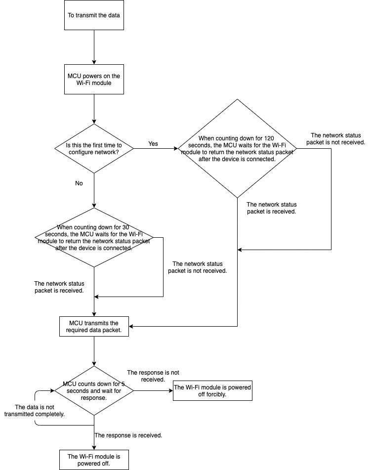
* The whole protocol applies to devices that use Wi-Fi modules and cannot use external power supply. During development of MCU programs, power-off management is especially important. Under the precondition of completing the functions, try to reduce the power-on time period of Wi-Fi module, in order to reduce the power consumption of devices. Overall control flow chart of data uploading is provided here. Developers can choose the required functions depending on device features. During development, developers can adjust relevant control logics as needed in a real-time way.
* In many cases, a device works normally when Wi-Fi function is not enabled. Due to various reasons, users might not be able to use Wi-Fi functions after they get the devices. To prevent electrical energy loss if Wi-Fi module is power on in this case, **we can design a physical button or relevant options in the device**. Only when the user presses this button or enables the options, the data changes, and MCU powers on the Wi-Fi module to transmit data.
### Protocol details
#### Querying product information
* Product ID: corresponding to product ID of Tuya IoT console. It is generated by Tuya IoT console to record product information in the cloud.
* Product information consists of product ID and MCU software version number.
* Define the format of MCU software version No.: dot-decimal notation, `x.x.x` (0<=x<=99), x is decimal digit.
| Field | Length (byte) | Description |
| ------------ | ------------- | ------------------------------------------------------------------------------------------------ |
| Header | 2 | 0x55aa |
| Version | 1 | 0x00 |
| Command word | 1 | 0x01 |
| Data length | 2 | 0x0000 |
| Data | 0 | None |
| Checksum | 1 | Start from the header, add up all the bytes, and then divide the sum by 256 to get the reminder. |
For example, the module sends the following command:
`55 aa 00 01 00 00 00`
**MCU returns the following command**
| Field | Length (byte) | Description |
| ------------ | ------------- | ------------------------------------------------------------------------------------------------ |
| Header | 2 | 0x55aa |
| Version | 1 | 0x00 |
| Command word | 1 | 0x01 |
| Data length | 2 | N |
| Data | N | {"p": "vHXEcqntLpkA\*\*\*\*", "v": "1.0.0"} |
| Checksum | 1 | Start from the header, add up all the bytes, and then divide the sum by 256 to get the reminder. |
For example, `{"p": "vHXEcqntLpkA****", "v": "1.0.0"}`,
* `p` represents product ID, `vHXEcqntLpkA****`, which is the product ID created by the user on the Tuya IoT console.
* `v` represents MCU version number, which is 1.0.0.
**MCU returns example information**
`55 aa 00 01 00 24 7b 22 70 22 3a 22 76 48 58 45 63 71 6e 74 4c 70 6b 41 6c 4f 73 79 22 2c 22 76 22 3a 22 31 2e 30 2e 30 22 7d bf`
#### Reporting the network status of the device
| Network Status of Device | Description | Status Value |
| ------------------------ | ---------------------------------------------------------- | ------------ |
| Status 1 | The configuration status is smartconfig | 0x00 |
| Status 2 | AP configuration status | 0x01 |
| Status 3 | Wi-Fi has been configured, but not connected to the router | 0x02 |
| Status 4 | Wi-Fi has been configured, and connected to the router | 0x03 |
| Status 5 | Wi-Fi has been connected to the router and the cloud | 0x04 |
| Status 6 | Wi-Fi device is in the low power consumption mode | 0x05 |
* When Wi-Fi status of the module changes, Wi-Fi status is sent to MCU.
* Status packet here is used by MCU device to get current status of the module. For status 1 and status 2, MCU shall configure network and display.
* In principle, users need to configure network in two ways. In the first network configuration way, a few routers have compatibility issues. The second network configuration way ensures that the device can be connected to the network.
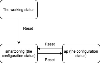
* Before network configuration, the power-on module is in the low power consumption status by default. After MCU sends Wi-Fi reset command, the module will enter the network configuration status.
* After the device is removed from a mobile phone, the module enters the low power consumption status. After MCU sends Wi-Fi reset command, the module will enter the status of waiting for network configuration.
* After the Wi-Fi module enters network configuration mode, if the module fails to connect the router within 10 seconds and the module is power-off, the module will be still in the previous network configuration status after it is powered on next time.
**The module sends the following command**
| Field | Length (byte) | Description |
| ------------ | ------------- | ------------------------------------------------------------------------------------------------------------------------------------------- |
| Header | 2 | 0x55aa |
| Version | 1 | 0x00 |
| Command word | 1 | 0x02 |
| Data length | 2 | 0x0001 |
| Data | 1 | Indicating Wi-Fi status:
0x00: status 1
0x01: status 2
0x02: status 3
0x03: status 4
0x04: status 5
0x05: status 6
|
| Checksum | 1 | Start from the header, add up all the bytes, and then divide the sum by 256 to get the reminder. |
For example, the module sends the following command:
`55 aa 00 02 00 01 04 06`, the device is connected to the router and the cloud.
**MCU returns the following command**
| Field | Length (byte) | Description |
| ------------ | ------------- | ------------------------------------------------------------------------------------------------ |
| Header | 2 | 0x55aa |
| Version | 1 | 0x00 |
| Command word | 1 | 0x02 |
| Data length | 2 | 0x0000 |
| Data | 0 | None |
| Checksum | 1 | Start from the header, add up all the bytes, and then divide the sum by 256 to get the reminder. |
**MCU returns the following command**
`55 aa 00 02 00 00 01`
#### Resetting Wi-Fi
Reset Wi-Fi status transfer is shown as follows.
**MCU sends the following command**
| Field | Length (byte) | Description |
| ------------ | ------------- | ------------------------------------------------------------------------------------------------ |
| Header | 2 | 0x55aa |
| Version | 1 | 0x00 |
| Command word | 1 | 0x03 |
| Data length | 2 | 0x0000 |
| Data | 0 | None |
| Checksum | 1 | Start from the header, add up all the bytes, and then divide the sum by 256 to get the reminder. |
**MCU sends the following command**
`55 aa 00 03 00 00 02`
**The module returns the following command**
| Field | Length (byte) | Description |
| ------------ | ------------- | ------------------------------------------------------------------------------------------------ |
| Header | 2 | 0x55aa |
| Version | 1 | 0x00 |
| Command word | 1 | 0x03 |
| Data length | 2 | 0x0000 |
| Data | 0 | None |
| Checksum | 1 | Start from the header, add up all the bytes, and then divide the sum by 256 to get the reminder. |
The module returns the following command:
`55 aa 00 03 00 00 02`
#### Resetting Wi-Fi and select configuration mode
**Note:**
* Compared to **Reset Wi-Fi**, with this frame, MCU can select the required configuration mode after Wi-Fi is reset.
* After connected to MCU, users can implement this protocol selectively.
**MCU sends the following command**
| Field | Length (byte) | Description |
| ------------ | ------------- | ------------------------------------------------------------------------------------------------ |
| Header | 2 | 0x55aa |
| Version | 1 | 0x00 |
| Command word | 1 | 0x04 |
| Data length | 2 | 0x0001 |
| Data | 1 | 0x00: enter smartconifg configuration mode,
0x01: enter AP configuration mode.
|
| Checksum | 1 | Start from the header, add up all the bytes, and then divide the sum by 256 to get the reminder. |
MCU sends the command to the control module and enters AP configuration mode:
55 aa 00 04 00 01 01 05
**The module returns the following command**
| Field | Length (byte) | Description |
| ------------ | ------------- | ------------------------------------------------------------------------------------------------ |
| Header | 2 | 0x55aa |
| Version | 1 | 0x00 |
| Command word | 1 | 0x04 |
| Data length | 2 | 0x0000 |
| Data | 0 | None |
| Checksum | 1 | Start from the header, add up all the bytes, and then divide the sum by 256 to get the reminder. |
The module returns the following command:
`55 aa 00 04 00 00 03`
#### Reporting the real-time status
Scenario: If a device **has an alert function** and requires real-time notification, we can use this command to report the relevant status data.
> **Note**: When MCU needs to report real-time status data, this protocol can be used to report the data.
* Status data is directly reported to the cloud, so the device shall be **connected to the cloud already**. Otherwise, the device fails to report the data.
* This command is a synchronous command. MCU reports the data, and then waits for the result returned by the module. The waiting timeout is 7 seconds.
* The module sends a network status packet that the server is connected, and then sends the required statistical data packet. The data uploading here does not have storage function. If, after a period, MCU does not receive the network status packet that the server is connected, the MCU will still power off the device.
* The waiting period in the preceding sentence is affected by network and whether it is the first network configuration. **If it is the first network configuration**, it takes much time to transfer from status 3 (Wi-Fi has been configured) to cloud connection status, **because the device shall be activated and initialized. It takes a longer time if the network is poor, so it is suggested that the waiting period should be 120 seconds**. If it is not the first network configuration, that is, the network has already been configured, it is suggested that the waiting period should be 30 seconds, considering that a longer waiting period is required in case of poor network.
* Support the reporting of multiple data units and single data unit. users can select the packet sending mode as needed. For specific data packet, refer to the following example.
The general operation flow chart is shown as follows.

**MCU sends the following command**
| Field | Length (byte) | Description |
| ----------- | ------------- | ----------------------------------------------------------------------------------------------- |
| Header | 2 | 0x55aa |
| Version | 1 | 0x00 |
| Command | 1 | 0x05 |
| Data Length | 2 | Depending on the type and quantity of **status data unit** |
| Data | N | One or multiple combined **status data unit** groups |
| Checksum | 1 | Start from the header, add up all the bytes, and then divide the sum by 256 to get the reminder |
**The module returns the following command**
| Field | Length (byte) | Description |
| ------------ | ------------- | ------------------------------------------------------------------------------------------------ |
| Header | 2 | 0x55aa |
| Version | 1 | 0x00 |
| Command word | 1 | 0x05 |
| Data length | 2 | 0x0001 |
| Data | 1 | 0x00: success, 0x01: failure |
| Checksum | 1 | Start from the header, add up all the bytes, and then divide the sum by 256 to get the reminder. |
**Example of reporting single status data unit:** Datapoint 109 has a boolean variable, and the value is 1 55 aa 00 05 00 05 6d 01 00 01 01 79.
**Example of reporting multiple status data units:** Datapoint 109 has a boolean variable, and the value is 1. Datapoint 102 has a string variable, and the value is `201804121507` (transmission corresponds to ASCII value): 55 aa 00 05 00 15 6d 01 00 01 01 66 03 00 0c 32 30 31 38 30 34 31 32 31 35 30 37 5d.
#### Reporting the recorded status
**Scenario**: A door lock contains multiple datapoint data, which shall be processed by the server as one record. In case of transient network failure, the data that cannot be reported will be saved through this command. **This command can report the status of record type devices**. **The report shall indicate the local time**.
**Note**: When MCU requires whole data that combines multiple datapoint and that shall be reported as a whole, this command can be used to send the data to Wi-Fi module. If the device is disconnected from network when the data is being reported, the module will save the data. **During the next data reporting, the module will upload the data**, and report it together with previously saved data.
* Each time when a previously saved record is reported successfully, **the module will send a returned packet with 09 command word data, which is 01**. **According to the returned packet, MCU will determine it as timeout, and power off**. When a record is sent, **MCU will wait for 5 seconds**. If no reply is received from the module, it is determined that an exception occurs, and the module will power off.
* With normal network, after the module is powered on, **it usually takes 4 seconds to connect the server**. Each time when there is record and the device is powered on, wait Wi-Fi module to send the device network status packet as described in the protocol document.
* **The waiting period is affected by network and whether it is the first network configuration**. If it is the first network configuration, it takes much time to transfer from status 3 (Wi-Fi has been configured) to status 5 (cloud connection status), because the device shall be activated and initialized. It takes a longer time if the network is poor, so it is suggested that the waiting period should be 120 seconds. If it is not the first network configuration, that is, the network has already been configured, it is suggested that the waiting period should be 30 seconds, considering that a longer waiting period is required in case of poor network. If the packet that the module has been connected to the server is not received when the waiting period expires, this command will be reported. After MCU reports the data, MCU will wait for the reporting results returned by the module.
* **Maximum length of data area reported in one record (multiple status data units) is 80**. The finally combined and actually saved data length might change, depending on the actual datapoint data. When no network is available, in case of exceeding the stipulated length, Wi-Fi module will return the result that the record cannot be sent.
* **Maximum 20 historical records can be saved by the module**. In case of exceeding the limit, the earliest records will be overwritten.
* When the Wi-Fi module receives a piece of data and successfully transmits it, or when there is no network state, **the record is stored in the flash successfully, which will also be regarded as the push success (00)**. When there is a successful push and a delay record, it will return `01`. In other cases, it will return `02` to represent the push failure.
* The use of time data is to guarantee that the recorded data is consistent with the actual events when the device is disconnected. If the time data is generated when the data transmission arrives at the server, the recorded data generated when the device is temporarily disconnected will be inconsistent with the actual event when the network is restored next time. **Therefore, when the device is connected to the Wi-Fi module for the first time, and the network performance is guaranteed, the desired time data can be obtained through the protocol. Each time when a record with the current device time data is transmitted, the Tuya cloud platform recognizes the time that is given by the device.**
* Since the device is involved in events such as **time zone and daylight saving time** around the world, the **recorded time processing** also should consider the difference between two time format standard. **When the device has no display screen, the device obtains the GMT through the protocol**, and when the relevant data is generated, it will transmit the GMT data of the current device operation according to the protocol. **Some devices, such as the door lock, need to display the local time, the lock can obtain the local time through the protocol**. The time module has can calculate the value based on the time zone or daylight saving time to guarantee that the time and the local time can be matched. When the relevant data is generated, the local time data of the device is transmitted according to the protocol.
**The workflow is shown as follows.**
**MCU sends the following command**
| Field | Length (byte) | Description |
| ------------ | ----------------------------------------------------------------------------- | ------------------------------------------------------------------------------------------------------------------------------------------------------------------------------------------------------------------------------------------------------------------------------------------------------------------------------------------------------------------------------------------------------------------------------------------------------------------------------------------------------------------------------------------------------------------------------------------------------------------------------------------------------------------------------------------------------------------------------------------------------------------------------------------------------------------------------------------------------------------------------------------------------------------------------------------------------------------------------------------------------------------------------------------------------------------------------------------------- |
| Header | 2 | 0x55aa |
| Version | 1 | 0x00 |
| Command word | 1 | 0x08 |
| Data length | 2 | It is depended on the type and number of the status data unit. |
| Data | 7 | 1. The data length is 7 bytes.
2. The Data\[0] indicates that whether a piece of data contains the flags of local time.
The 0 indicates that the local time of the door lock is not contained, and the module ignores the data.
While 1 indicates the time information is contained, which is the local time of the door lock.
And 2 indicates the time information is contained, which is in the GMT format.
3. Data\[1] represents the year, for example, 0X00 indicates the year of 2000.
4. Data\[2] represents the month, which starts from 1 and ends on 12.
5. Data\[3] represents the date, which starts from 1 and ends on 31.
6. Data\[4] represents the hour, which starts from 0 and ends on 23.
7. Data\[5] represents the minute, which starts from 0 and ends on 59.
8. Data\[6] represents the second, which starts from 0 and ends on 59.
|
| N | One or more data. For more information, see the **Status data unit** section. | None. |
| Checksum | 1 | Start from the header, add up all the bytes, and then divide the sum by 256 to get the reminder. |
**The module returns the following command.**
| Field | Length (byte) | Description |
| ------------ | ------------- | ------------------------------------------------------------------------------------------------------------------------------------------------------------------------------------- |
| Header | 2 | 0x55aa |
| Version | 1 | 0x00 |
| Command word | 1 | 0x08 |
| Data length | 2 | 0x0001 |
| Data | 1 | 0X00: the transmission is successful.
0X01: the record is successfully transmitted, however there are stranded recorded to be transmitted.
0X02: the transmission fails.
|
| Checksum | 1 | Start from the header, add up all the bytes, and then divide the sum by 256 to get the reminder. |
Examples of data packet transmission is shown as follows.
**For the transmission example of one status data unit:**
The DP of 109 is a Boolean type variable, and the value is `1`.
* If the time complies with the server time.
`55 aa 00 08 00 0c 00 12 04 13 0d 04 14 ++*6d 01 00 01 01*++ d1`
* If the time complies with the local time of the device, for example, 2018/04/19 13:03:29 of Beijing time.
`55 aa 00 08 00 0c 01 12 04 13 0d 03 1d ++*6d 01 00 01 01*++ da`
* If the time complies with the local time of the device in the GMT format, for example, 2018/04/19 5:03:29 +0.
`55 aa 00 08 00 0c 02 12 04 13 05 03 1d ++*6d 01 00 01 01*++ d3`
**For the transmission examples of more status data units:**
* The DP of 109 is a Boolean type variable, and the value is `1`.
* The DP of 102 is a string type variable, and the value is an ASCII code of `201804121507`.
* If the time complies with the time of the Tuya cloud platform.
`55 aa 00 08 00 1c 00 12 04 13 0d 06 04 *6d 01 00 01 01* *66 03 00 0c 32 30 31 38 30 34 31 32 31 35 30 37* a7`
* If the time complies with the local time of the device, for example, 2018/04/19 13:03:29 of Beijing time.
`55 aa 00 08 00 1c 01 12 04 13 0d 08 2e ++*6d 01 00 01 01*++ 66 03 00 0c 32 30 31 38 30 34 31 32 31 35 30 37 d4`
* If the time complies with the local time of the device in the GMT format, for example, 2018/04/19 5:03:29 +0.
`55 aa 00 08 00 1c 02 12 04 13 05 08 2e ++*6d 01 00 01 01*++ 66 03 00 0c 32 30 31 38 30 34 31 32 31 35 30 37 cd`
**If more than one unlocking method is used, see the following description.**
> **Note**: according to the DP ID of the used unlocking method, the data packet transmits the data of the related DPs, so as to transmit to related data for all of the used unlocking methods.
If the password and fingerprint recognition is used, `55 aa 00 08 00 17 00 13 02 0D 06 33 03 02 02 00 04 00 00 00 01` will be transmitted for the password method, while `01 02 00 04 00 00 00 05 91` will be transmitted for the fingerprint recognition method.
#### Reception of module command
The reception of command complies with asynchronous processing protocol. When the MCU receives the data packet, it responds to the module about the reception and controls the device according to the command, and the MCU status response is transmitted in the status reporting of the MCU.
**The module sends the following command**
| Field | Length (byte) | Description |
| ------------ | ------------- | ------------------------------------------------------------------------------------------------ |
| Header | 2 | 0x55aa |
| Version | 1 | 0x00 |
| Command word | 1 | 0x09 |
| Data length | 2 | It is depended on the type and number of the status data unit. |
| Data | N | See the Command data unit section. |
| Checksum | 1 | Start from the header, add up all the bytes, and then divide the sum by 256 to get the reminder. |
The command sent by module is shown as follows. The DP of 3 is a Boolean type variable, and the value for unlocking command is `1`.
`55 aa 00 09 0005 *03 01 00* *01 01* 13`
**Response from the MCU**
| Field | Length (byte) | Description |
| ------------ | ------------- | ------------------------------------------------------------------------------------------------ |
| Header | 2 | 0x55aa |
| Version | 1 | 0x00 |
| Command word | 1 | 0x09 |
| Data length | 2 | 0x0000 |
| Data | 0 | None |
| Checksum | 1 | Start from the header, add up all the bytes, and then divide the sum by 256 to get the reminder. |
ACK response from the MCU
`55 aa 03 09 00 00 0b`
#### Inquiry of the local time
* After the device is connected, and the device status 5 is received by the cloud, the module and others can query the local time of the device.
* If the network performance is poor, the inquiry of the local time may fail even the device is connected to the cloud. For time-dependent devices such as door locks, if the local time is not calibrated, the inquiry fails. It is necessary to query the time repeatedly every 3 seconds to guarantee the success of time data acquisition.
**MCU sends the following command**
| Field | Length (byte) | Description |
| ------------ | ------------- | ------------------------------------------------------------------------------------------------ |
| Header | 2 | 0x55aa |
| Version | 1 | 0x00 |
| Command word | 1 | 0x06 |
| Data length | 2 | 0x0000 |
| Data | 0 | None |
| Checksum | 1 | Start from the header, add up all the bytes, and then divide the sum by 256 to get the reminder. |
Local time inquiry example by the MCU:
`55 aa 00 06 00 00 05`
**The module returns the following command**
| Field | Length (byte) | Description |
| ------------ | ------------- | --------------------------------------------------------------------------------------------------------------------------------------------------------------------------------------------------------------------------------------------------------------------------------------------------------------------------------------------------------------------------------------------------------------------------------------------------------------------------------------------------------------------------------------------------------------------------------------------------------------------------------------------------------------------------------------------------------------------------------------------------------------------------------------------------------------------------------------------------------------------------------------------------------------------------------------------------- |
| Header | 2 | 0x55aa |
| Version | 1 | 0x00 |
| Command word | 1 | 0x06 |
| Data length | 2 | 0x0008 |
| Data | Data | The data length is 8 bytes.
The Data\[0] represents that whether the inquiry is successful or not.
Data\[1] represents the year, for example, 0X00 indicates the year of 2000. Data\[2] represents the month, which starts from 1 and ends on 12.
Data\[3] represents the date, which starts from 1 and ends on 31.
Data\[4] represents the hour, which starts from 0 and ends on 23.
Data\[5] represents the minute, which starts from 0 and ends on 59.
Data\[6] represents the second, which starts from 0 and ends on 59.
Data\[7] indicates the week, which starts from 1 and ends on 7. The 1 indicates the Monday.
|
| Checksum | 1 | Start from the header, add up all the bytes, and then divide the sum by 256 to get the reminder. |
**Local time response example by the module**
`55 aa 00 06 00 08 01 12 09 11 10 09 05 01 59`
The preceding example represents the local time of Monday, September 17, 2018, 16:09:05.
* If the device is activated in mainland China, the local time is Beijing time (East 8 District).
* If the device is activated in other countries or regions, the local time is the time zone in which the device is located.
#### Inquiry of the time in GMT format
* **The GMT does not have time zone and daylight saving time related factors**. If the dynamic password function is enabled for a device such as a door lock but does not need to display the local time of the device, **the device only uses GMT**, the transmitted data is in record type and must be in the GMT format.
* If the dynamic password function is enabled for a device such as a door lock and needs to display the local time of the device, when the device uses GMT, in addition to obtaining the local time regularly, **the time difference between GMT and the local time must also be stored locally**. When displaying the local time, the device adds the time difference on the basis of GMT. When the data is transmitted in the channel of record data, the time must be in the GMT format.
**MCU sends the following command**
| Field | Length (byte) | Description |
| ------------ | ------------- | ------------------------------------------------------------------------------------------------ |
| Header | 2 | 0x55aa |
| Version | 1 | 0x00 |
| Command word | 1 | 0x10 |
| Data length | 2 | 0x0000 |
| Data | 0 | None |
| Checksum | 1 | Start from the header, add up all the bytes, and then divide the sum by 256 to get the reminder. |
GMT inquiry example by the MCU:
`55 aa 00 10 00 00 0F`
**The module returns the following command**
| Field | Length (byte) | Description |
| ------------ | ------------- | -------------------------------------------------------------------------------------------------------------------------------------------------------------------------------------------------------------------------------------------------------------------------------------------------------------------------------------------------------------------------------------------------------------------------------------------------------------------------------------------------------------------------------------------------------------------------------------------------------------------------------------------------------------------------------------------------------------------------------------------------------------------------------------------------------------------------------------------------------------------------------------------------------------------------------------------------- |
| Header | 2 | 0x55aa |
| Version | 1 | 0x00 |
| Command word | 1 | 0x10 |
| Data length | 2 | 0x0008 |
| Data | 8 | The data length is 8 bytes.
The Data\[0] represents that whether the inquiry is successful or not.
Data\[1] represents the year, for example, 0X00 indicates the year of 2000.
Data\[2] represents the year, which starts from 1 and ends on 12. Data\[3] represents the date, which starts from 1 and ends on 31.
Data\[4] represents the hour, which starts from 0 and ends on 23.
Data\[5] represents the minute, which starts from 0 and ends on 59.
Data\[6] represents the second, which starts from 0 and ends on 59.
Data\[7] indicates the week, which starts from 1 and ends on 7. The 1 indicates the Monday.
|
| Checksum | 1 | Start from the header, add up all the bytes, and then divide the sum by 256 to get the reminder. |
GMT response example by the module:
`55 aa 00 10 00 08 01 12 09 11 08 15 03 01 65`
The preceding example represents the of Monday, September 17, 2018, 8:09:05.
#### Network performance test of Wi-Fi
**Note:**
* `tuya\_mdev\_test` scans the specific SSID and returns the result and the signal strength percentage.
* If you send the production testing command to the device, the device must be initialized and has responded to the product information query for the first time. Otherwise, the production testing will fail or have no result.
* This command is mostly used for testing the finished product during mass production.
* The production testing router has no restriction on password setting. But the band of the router must be 2.4G.
**MCU sends the following command**
| Field | Length (byte) | Description |
| ------------ | ------------- | ------------------------------------------------------------------------------------------------ |
| Header | 2 | 0x55aa |
| Version | 1 | 0x00 |
| Command word | 1 | 0x07 |
| Data length | 2 | 0x0000 |
| Data | Data | None |
| Checksum | 1 | Start from the header, add up all the bytes, and then divide the sum by 256 to get the reminder. |
MCU makes network performance test requests to module:
`55 aa 00 07 00 00 06`
**The module returns the following command**
| Field | Length (byte) | Description |
| ------------ | ------------- | ----------------------------------------------------------------------------------------------------------------------------------------------------------------------------------------------------------------------------------------------------------------------------------------------------------------------------------------------------------------------------------------------------------------------------------------------------------------------------------------------------------------------------------------------------------------------------------------------------------------------------------------------------------------------------- |
| Header | 2 | 0x55aa |
| Version | 1 | 0x00 |
| Command word | 1 | 0x07 |
| Data length | 2 | 0x0002 |
| Data | 2 | The data length is 2 bytes.
Data\[0]: the valid values are 0X00 and 0X01, which represent failure and success respectively.
Data\[1]: indicates the network stability, the valid values range from 0 to 100, and 100 represents the most stable network performance.
When the Data\[0] is set to 0X00, the Data\[1] will point out why the testing fails, and Data\[0]=0X00 indicates that no SSID is scanned.
Data\[1]=0X01 indicates that the authorization key is not burned to the module.
|
| Checksum | 1 | Start from the header, add up all the bytes, and then divide the sum by 256 to get the reminder. |
Testing response example transmitted by module:
`55 aa 00 07 00 02 01 50 59`
The preceding example represents that the network stability scores 80.
#### Upgrading the Wi-Fi module firmware
The power-on and power-off of Wi-Fi module are controlled by MCU. To upgrade the Wi-Fi module firmware, MCU can send the following command to make requests for the latest firmware. \* **The MCU main board powers off the Wi-Fi module according to the returned packet from Wi-Fi module**.
When the MCU transmits `0a` but receives no response after waiting for 5 second, then the MCU powers off the Wi-Fi module. If the reply from the module indicates that firmware is being upgraded, the MCU must monitor the upgrading for a while. For example, if the MCU does not receive a response of successful firmware upgrading after 60 seconds, it is considered that the firmware upgrading fails and the Wi-Fi module needs to be powered off.
**MCU sends the following command**
| Field | Length (byte) | Description |
| ------------ | ------------- | ------------------------------------------------------------------------------------------------ |
| Header | 2 | 0x55aa |
| Version | 1 | 0x00 |
| Command word | 1 | 0x0a |
| Data length | 2 | 0x0000 |
| Data | 0 | None |
| Checksum | 1 | Start from the header, add up all the bytes, and then divide the sum by 256 to get the reminder. |
Firmware upgrading request example sent by MCU:
`55 aa 00 0a 00 00 09`
**The module returns the following command**
| Field | Length (byte) | Description |
| ------------ | ------------- | ------------------------------------------------------------------------------------------------------------------------------------------------------------------------------------------------------------------------------------------------------------------------------------------------------------------------------------------------------------- |
| Header | 2 | 0x55aa |
| Version | 1 | 0x00 |
| Command word | 1 | 0x0a |
| Data length | 2 | 0x0001 |
| Data | 1 | 0X00: starts to check for firmware upgrade, and power-off is not allowed.
0X01: the firmware is the latest one, and power-off is allowed.
0X02: the firmware is being upgraded, and power-off is not allowed.
0X03: the firmware is upgraded, and power-off is allowed.
0X04: the firmware fails to be upgraded, and power-off is allowed.
|
| Checksum | 1 | Start from the header, add up all the bytes, and then divide the sum by 256 to get the reminder. |
Firmware upgrading response example from module:
* `55 aa 00 0a 00 01 00 0a`: it is responded immediately after receiving the upgrading request.
* `55 aa 00 0a 00 01 01 0b`: indicates that there is no firmware to upgrade after querying the server.
#### Upgrading the MCU firmware
* When MCU receives the firmware update completion instruction returned by the module, **it indicates that the upgrade files of the server MCU have been obtained completely** and the serial data transmission has been completed. Note that after receiving the complete upgrade file, the MCU confirms that there is no problem about the file. At this time, the module re-sends the query information. MCU needs to return the relevant **product information** and **update the new software version number to the Tuya cloud platform**.
* At present, the maximum MCU OTA size is 480 KB.
* When you configure MCU upgrade on the Tuya IoT console, the MCU upgrade mode is **app silent upgrade**.
**MCU sends the following command**
| Field | Length (byte) | Description |
| ------------ | ------------- | ------------------------------------------------------------------------------------------------ |
| Header | 2 | 0x55aa |
| Version | 1 | 0x00 |
| Command word | 1 | 0x0c |
| Data length | 2 | 0x0000 |
| Data | 0 | None |
| Checksum | 1 | Start from the header, add up all the bytes, and then divide the sum by 256 to get the reminder. |
Example of upgrading the MCU firmware by MCU
`55 aa 00 0c 00 00 0b`
**The module returns the following command**
| Field | Length (byte) | Description |
| ------------ | ------------- | ------------------------------------------------------------------------------------------------------------------------------------------------------------------------------------------------------------------------------------------------------------------------------------------------------------------------------------------------------------- |
| Header | 2 | 0x55aa |
| Version | 1 | 0x00 |
| Command word | 1 | 0x0c |
| Data length | 2 | 0x0001 |
| Data | 1 | 0X00: starts to check for firmware upgrade, and power-off is not allowed.
0X01: the firmware is the latest one, and power-off is allowed.
0X02: the firmware is being upgraded, and power-off is not allowed.
0X03: the firmware is upgraded, and power-off is allowed.
0X04: the firmware fails to be upgraded, and power-off is allowed.
|
| Checksum | 1 | Start from the header, add up all the bytes, and then divide the sum by 256 to get the reminder. |
Firmware upgrading response example from module:
* `55 aa 00 0c 00 01 00 0c`: it is responded immediately after receiving the upgrading request.
* `55 aa 00 0c 00 01 01 0d`: indicates that there is no firmware to upgrade after querying the server.
#### Starting to upgrade
When the MCU triggers the module to upgrade the MCU firmware, the Tuya cloud platform has also prepared a newer version of MCU firmware, and the upgrade method is applicable to the MCU, the module will return **the file size of the MCU firmware package** that needs to be upgraded.
**For example, the module sends the following command**
| Field | Length (byte) | Description |
| ------------ | ------------- | ------------------------------------------------------------------------------------------------------------------------------------ |
| Header | 2 | 0x55aa |
| Version | 1 | 0x00 |
| Command word | 1 | 0x0d |
| Data length | 2 | 0x0004 |
| Data | 4 | The size of the firmware file is in byte measurement, the data type is unsigned integer, and the data storage is in big-endian mode. |
| Checksum | 1 | Start from the header, add up all the bytes, and then divide the sum by 256 to get the reminder. |
Example of a package size sent by module:
`55 aa 00 0d 00 04 00 00 68 00 78`: the size of firmware package is 26624 bytes, namely 26KB.
**MCU returns the following command**
| Field | Length (byte) | Description |
| ------------ | ------------- | ------------------------------------------------------------------------------------------------ |
| Header | 2 | 0x55aa |
| Version | 1 | 0x00 |
| Command word | 1 | 0x0d |
| Data length | 2 | 0x0000 |
| Data | 0 | None |
| Checksum | 1 | Start from the header, add up all the bytes, and then divide the sum by 256 to get the reminder. |
ACK response form the MCU:
55 aa 00 0d 00 00 0c
#### Upgrade packet transmission
**Note:**
* The data type of upgrade packet offset is unsigned short, and the packet data does not have specific type.
* If the MCU receives the frame with data length less than 4 and the upgrade packet offset is equal to or greater than the size of firmware, the packet transmission ends.
**For example, the module sends the following command**
| Field | Length (byte) | Description |
| ------------ | ------------- | ------------------------------------------------------------------------------------------------ |
| Header | 2 | 0x55aa |
| Version | 1 | 0x00 |
| Command word | 1 | 0x0e |
| Data length | 2 | The data length is the sum of 0X0004 and the data packet length. |
| Data | N | The first 4 bytes is fixed as packet offset, and the latter bytes is the packet. |
| Checksum | 1 | Start from the header, add up all the bytes, and then divide the sum by 256 to get the reminder. |
**Example of a package sent by module**
If the file to be upgraded has 530 bytes in size, under this circumstance, the MCU can skip the response for the last data packet.
* For the first packet data, packet offset is 0x00000000, and data packet length is 256.
`55aa 00 0e 0104 00000000 xx…xx XX`
* For the second packet data, packet offset is 0x00000100, and data packet length is 256.
`55aa 00 0e 0104 00000100 xx…xx XX`
* For the third packet data, packet offset is 0x00000200, and data packet length is 18.
`55aa 00 0e 0016 00000200 xx…xx XX`
* For the last packet data, packet offset is 0x00000212, and data packet length is 0.
`55aa 00 0e 0004 00000212 xx...xx XX`
**MCU returns the following command**
| Field | Length (byte) | Description |
| ------------ | ------------- | ------------------------------------------------------------------------------------------------ |
| Header | 2 | 0x55aa |
| Version | 1 | 0x00 |
| Command word | 1 | 0x0e |
| Data length | 2 | 0x0000 |
| Data | 0 | None |
| Checksum | 1 | Start from the header, add up all the bytes, and then divide the sum by 256 to get the reminder. |
Confirm each MCU data packet:
`55aa 00 0e 0000 0d`
#### Checking the signal strength of the connected router
The precondition of checking the signal strength of the currently connected router is that **MCU receives the network status packet of the device, indicating the device has successfully connected to the router**. Otherwise, sending this command will return failed.
**MCU sends the following command**
| Field | Length (byte) | Description |
| ------------ | ------------- | ------------------------------------------------------------------------------------------------ |
| Header | 2 | 0x55aa |
| Version | 1 | 0x00 |
| Command word | 1 | 0x0b |
| Data length | 2 | 0x0000 |
| Data | 0 | None |
| Checksum | 1 | Start from the header, add up all the bytes, and then divide the sum by 256 to get the reminder. |
MCU receives the signal strength percentage of the connected router:
`55 aa 00 0b 00 00 0a`
**The module returns the following command**
| Field | Length (byte) | Description |
| ------------ | ------------- | ------------------------------------------------------------------------------------------------------------------------------------------------------------------------------------------------------------------------------------------------------------------------------------------------------------------------------------------------------------------------------------------------ |
| Header | 2 | 0x55aa |
| Version | 1 | 0x00 |
| Command word | 1 | 0x0b |
| Data length | 2 | 0x0002 |
| Data | 2 | If data length is 2 bytes:
For Data\[0], 0x00 indicates failure, and 0x01 for success.
When Data\[0] is 0x01, Data\[1] indicates signal strength (from 0 to 100, 0 for the weakest, 100 for the strongest).
When Data\[0] is 0x00, if Data\[1] is 0x00, it indicates the device is not connected to the router.
|
| Checksum | 1 | Start from the header, add up all the bytes, and then divide the sum by 256 to get the reminder. |
Module returns current value of strength (`80`):
`55 aa 00 0b 00 02 01 50 5D`
#### Requesting cloud temporary password (only support single password)
* To obtain currently valid password, creating a password for current time on the App-end is required.
* This interface only supports obtaining one temporary password. Since this interface is for the general firmware 1.0.0 contained in early door lock, using in combination with corresponding early door lock panel is necessary. **For all module firmware of later version (later than 1.0.0), the temporary password of App panel uses interface that supports multiple temporary passwords.** Obtain related password data.
**MCU sends the following command**
| Field | Length (byte) | Description |
| ------------ | ------------- | ------------------------------------------------------------------------------------------------ |
| Header | 2 | 0x55aa |
| Version | 1 | 0x00 |
| Command word | 1 | 0x11 |
| Data length | 2 | 0x0000 |
| Data | 0 | None |
| Checksum | 1 | Start from the header, add up all the bytes, and then divide the sum by 256 to get the reminder. |
The lock obtains currently valid temporary password:
`55 aa 00 11 00 00 10`
**The module returns the following command**
| Field | Length (byte) | Description |
| ------------ | ------------- | -------------------------------------------------------------------------------------------------------------------------------------------------------------------------------------------------------------------------------------------------------------------------------------------------------------------------------------------------------------------------------------------------------------------------------------------------------------------------------------------------------------------------------------------------------------------------------------------------------------------------------------------------------------------------------------------------------------------------------------------------------------------------------------------------------------- |
| Header | 2 | 0x55aa |
| Version | 1 | 0x00 |
| Command word | 1 | 0x11 |
| Data length | 2 | 0x0007+N (temporary password) |
| Data | 7+N | If data length is 7+N bytes:
Data\[0] indicates if the password is successfully got. 0 is returned for failure without any password and data of valid period. If data content length is 1, it indicates the valid expiration date of the success password (GMT).
Data\[1] represents the year, for example, 0X00 indicates the year of 2000.
Data\[2] is month, from 1 to 12.
Data\[3] represents the date, which starts from 1 and ends on 31.
Data\[4] represents the hour, which starts from 0 and ends on 23.
Data\[5] is minute, from 0 to 59. Data\[6] is second, from 0 to 59. Temporary password (N) is the ASLL characters of password data transmission characters.
|
| Checksum | 1 | Start from the header, add up all the bytes, and then divide the sum by 256 to get the reminder. |
Module returns current password:
`55 aa 00 11 00 0d 01 10 04 13 05 06 07 31 32 33 34 35 36 8c`
At 05:06:07 on April 19, 2016 (GMT)
Password: “123456”. **ASCII character is used for password transmission**.
#### Checking dynamic password
* The time data in the protocol is used to operate current dynamic password. The operation time here is the current GMT. Therefore, the device is required to send GMT data to the module.
* **The permission to check the dynamic password can be set on the App-end**. The generation algorithm of dynamic password uses admin password to contribute hybrid computation of result. Each time the device requests to check the dynamic password, **it is required to send all the admin password of current door lock to the module**.
* The data length of the sent packet is at least 15 bytes, including time data + password + the number of transmitted admin password (excluding optional admin password)
**MCU sends the following command**
| Field | Length (byte) | Description |
| ------------ | ------------------------------------------------------------------------------------------------------------------------------------------------------- | ------------------------------------------------------------------------------------------------------------------------------------------------------------------------------------------------------------------------------------------------------------------------------------------------------------------------------------------------------------------------------------------------------------------------------------------------------------------------------------------------------------------------------------------------------ |
| Header | 2 | 0x55aa |
| Version | 1 | 0x00 |
| Command word | 1 | 0x12 |
| Data length | 2 | 0x0006+0x08+0x01+N |
| Data | 6 | If data length is 6 bytes, current GMT of the device:
Data\[0] represents year, 0x00 indicates the year of 2000. Data\[1] represents month, from 1 to 12.
Data\[2] represents the date, which starts from 1 and ends on 31.
Data\[3] represents the hour, which starts from 0 and ends on 23.
Data\[4] represents the minute, which starts from 0 and ends on 59.
Data\[5] represents second, from 0 to 59.
|
| 8 | Password data of user input: Data\[6] to Data\[13]
Data content ranges from '0' to '9'. ASCII character is used for data transmission.
| None. |
| 1 | The number of admin password (0 to 10).
The corresponding data of number is required.
| None. |
| 1 | The length of admin password (no longer than 8 bytes). | None. |
| N | For the first admin password (password must be figures). Data content ranges from '0' to '9'.
ASCLL character is used for data transmission.
| None. |
| N | For the second admin password (password must be figures). Data content ranges from '0' to '9'.
ASCLL character is used for data transmission.
| None. |
| ... | ... | ... |
| Checksum | 1 | Start from the header, add up all the bytes, and then divide the sum by 256 to get the reminder. |
MCU sends two data packets of 6-byte admin password.
`55 aa 00 12 00 1C 12 09 11 06 22 29 31 35 39 35 30 31 35 38 02 06 *35 32 31 33 31 34* 35 32 31 33 31 33 b3`
Data of the first password: `521314`.
Data of the second password: `521313`.
**The module returns the following command**
| Field | Length (byte) | Description |
| ------------ | ------------- | -------------------------------------------------------------------------------------------------------------------------------------------------------------------- |
| Header | 2 | 0x55aa |
| Version | 1 | 0x00 |
| Command word | 1 | 0x12 |
| Data length | 2 | 0x0001 |
| Data | 1 | 0x00 (Password verification passed). 0x01 (Password verification failed)//Communication operation error code 0x02 (Device is not activated) 0x03 (Data length error) |
| Checksum | 1 | Start from the header, add up all the bytes, and then divide the sum by 256 to get the reminder. |
Module returning password validation failed.
`55 aa 00 12 00 01 01 13`
#### Requesting cloud temporary password (supports multiple group)
* To distinguish it from other passwords, **the App panel of temporary password uses 7-digit significant figures**. This interface is deployed only when the door lock MCU detects that multiple sets of temporary password are used. Then, related data will be obtain from the cloud to update the data and status of local password, which can reduce energy consumption to the greatest extent.
* Note that the related time data sent from module to the door lock is **GMT**. It is necessary to sync time data of the door lock by getting the GMT interface locally.
* The password is delivered in full by the server each time. Therefore, the lock needs to be updated accordingly based on all the passwords and status returned by the server.
**MCU sends the following command**
| Field | Length (byte) | Description |
| ------------ | ------------- | ------------------------------------------------------------------------------------------------ |
| Header | 2 | 0x55aa |
| Version | 1 | 0x00 |
| Command word | 1 | 0x13 |
| Data length | 2 | 0x0000 |
| Data | 0 | None |
| Checksum | 1 | Start from the header, add up all the bytes, and then divide the sum by 256 to get the reminder. |
The lock obtains currently valid temporary password:
`55 aa 00 13 00 00 12`
**The module returns the following command**
| Field | Length (byte) | Description |
| ------------ | ------------- | ------------------------------------------------------------------------------------------------------------------------------------------------------------------------------------------------------------------------------------------------------------------------------------------------------------------------------------------------------------------------------------------------------------------------------------------------------------------------------------------------------------------------------------------------------------------------------------------------------------------------------------------------------------------------------------------------------------------------------------------------------------------------------------------------------------------------------------------------------------------------------------------------------------------------------------------------------------------------------------------------------------------------------------------------------------------------------------------------------------------------------------------------------------------------------------------------------------------------------------------------------------------------------------------------------------------------------------------------------------------------------------------------------------------------------------------------------------------------------------------------------------------------------------------------------------------------------------------------------------------------------------------------------------------------------------------------------------------------------------------------------ |
| Header | 2 | 0x55aa |
| Version | 1 | 0x00 |
| Command word | 1 | 0x13 |
| Data length | 2 | 0x0001+N (temporary password) |
| Data | 1+N | If data length is 1+N bytes:
Data\[0] indicates if the password is successfully got. 0 is returned for failure without any password and data of valid period. If data content length is 1, it indicates success.
Data\[1] password quantity (0 to 10). 0 indicates no password is created Related data of password and valid period aren't transmitted through the serial.
Data\[2] password length (the length of each password should be kept consistent) //Data of the first password
Data\[3] password No. (adding 900 to the password No. to get the actual No.) (150)
Data\[4] valid usage count of password. 0 indicates the number of using this password to unlock is unlimited within the expiry date. 1 indicates the password can only unlock once within the expiry date.
Data\[5] if current status of the password is 0, it indicates the password is valid. If it is 1, it indicates the password is deleted by the panel and is invalid. Valid date (GMT)
Data\[6] is year, 0x00 is for the year of 2000
Data\[7] is month, from 1 to 12.
Data\[8] is date, from 1 to 31.
Data\[9] is hour, from 0 to 23.
Data\[10] is minute, from 0 to 59.
Data\[11] is second, from 0 to 59, expiry date of the password (GMT)
Data\[12] is month, 0x00 is for the year of 2000
Data\[13] is month, from 1 to 12.
Data\[14] is date, from 1 to 31.
Data\[15] is hour, from 0 to 23.
Data\[16] is minute, from 0 to 59.
Data\[17] represents the second, which starts from 0 and ends on 59.
Temporary password (the byte N=data\[2]) (ASLL code is used for transmission)
//Data of the second of password............
|
| Checksum | 1 | Start from the header, add up all the bytes, and then divide the sum by 256 to get the reminder. |
Wi-Fi module returns current 10 passwords:
```
55 AA 00 13 00 DF 01 0A 07
0A 00 00 12 06 1C 08 15 07 14 05 16 13 01 07 31 32 33 34 35 36 37
09 00 00 12 06 1C 08 15 07 14 05 16 13 01 07 31 32 33 34 35 36 37
08 00 00 12 06 1C 08 15 07 14 05 16 13 01 07 31 32 33 34 35 36 37
07 00 00 12 06 1C 08 15 07 14 05 16 13 01 07 31 32 33 34 35 36 37
06 00 00 12 06 1C 08 15 07 14 05 16 13 01 07 31 32 33 34 35 36 37
05 00 00 12 06 1C 08 15 07 14 05 16 13 01 07 31 32 33 34 35 36 37
04 00 00 12 06 1C 08 15 07 14 05 16 13 01 07 31 32 33 34 35 36 37
03 00 00 12 06 1C 08 15 07 14 05 16 13 01 07 31 32 33 34 35 36 37
02 00 00 12 06 1C 08 15 07 14 05 16 13 01 07 31 32 33 34 35 36 37
01 00 00 12 06 1C 08 15 07 14 05 16 13 01 07 31 32 33 34 35 36 37
C6
```
#### Requesting cloud temporary password (with schedule list)
* To distinguish it from other passwords, **the App panel of temporary password uses 7-digit significant figures**. This interface is deployed only when the lock MCU detects that multiple sets of temporary password are used. Then, related data will be obtain from the cloud to update the data and status of local password, which can reduce energy consumption to the greatest extent.
* Note that the related time data sent from module to the lock is **GMT**. It is necessary to sync time data of the lock by getting the GMT interface locally.
* The password is delivered in full by the server each time. Therefore, the lock needs to be updated accordingly based on all the passwords and status returned by the server.
* Keep the original effective period setting, **on the basis of the effective period**, you can set the password effective plan according to the weekly repeat method; up to 3 schedules can be added
**MCU sends the following command**
| Field | Length (byte) | Description |
| ------------ | ------------- | ------------------------------------------------------------------------------------------------ |
| Header | 2 | 0x55aa |
| Version | 1 | 0x00 |
| Command word | 1 | 0x14 |
| Data length | 2 | 0x0000 |
| Data | 0 | None |
| Checksum | 1 | Start from the header, add up all the bytes, and then divide the sum by 256 to get the reminder. |
The lock obtains currently valid temporary password:
`55 aa 00 14 00 00 13`
**The module returns the following command**
| Field | Length (byte) | Description |
| ------------ | ------------- | ---------------------------------------------------------------------------------------------------------------------------------------------------------------------------------------------------------------------------------------------------------------------------------------------------------------------------------------------------------------------------------------------------------------------------------------------------------------------------------------------------------------------------------------------------------------------------------------------------------------------------------------------------------------------------------------------------------------------------------------------------------------------------------------------------------------------------------------------------------------------------------------------------------------------------------------------------------------------------------------------------------------------------------------------------------------------------------------------------------------------------------------------------------------------------------------------------------------------------------------------------------------------------------------------------------------------------------------------------------------------------------------------------------------------------------------------------------------------------------------------------------------------------------------------------------------------------------------------------------------------------------------------------------------------------------------------------------------------------------------------------------------------------------------------------------------------------------------------------------------------------------------------------------------------------------------------------------------------------------------------------------------------------------------------------------------------------------------------------------------------------------------------------------------------------------------------------------------------------------------------------------------------------------------------------------------------------------------------------------------------------------------------------------------------------------------------------------------- |
| Header | 2 | 0x55aa |
| Version | 1 | 0x00 |
| Command word | 1 | 0x14 |
| Data length | 2 | 0x0001+N (temporary password) |
| Data | 1+N | If data length is 1+N bytes:
Data\[0] indicates whether the password is successfully obtained. 0 is returned for failure without any password and data of valid period. If data content length is 1, it indicates success.
Data\[1] password quantity (0 to 10). 0 indicates no password is created. Related data of password and valid period aren't transmitted via the serial*. \*\*The password quantity is included in this packet data.*
Data\[2] password length (the length should be kept consistent)
Data\[3] bit7: if there is subsequent data packet. Bit6-bit0: the No. of this packet. (Start from 0) //Data of the first password
Data\[4] password No. (adding 900 to the password No. to get the actual No.) (1 to 50)
Data\[5] valid usage count of password. 0 indicates the number of using this password to unlock is unlimited within the expiry date. 1 indicates the password can only unlock once within the expiry date
Data\[6] if current status of the password is 0, it indicates the password is valid. If it is 1, it indicates the password is deleted by the panel and is invalid. Valid date (GMT):
Data\[7] is year, 0x00 is for the year of 2000
Data\[8] is month, from 1 to 12.
Data\[9] is date, from 1 to 31.
Data\[10] is hour, from 0 to 23.
Data\[11] is minute, from 0 to 59.
Data\[12] is second, from 0 to 59, expiry date of the password (GMT):
Data\[13] is year, 0x00 is for the year of 2000
Data\[14] is month, from 1 to 12.
Data\[15] is date, from 1 to 31.
Data\[16] is hour, from 0 to 23.
Data\[17] is minute, from 0 to 59.
Data\[18] is second, from 0 to 59, expiry date of the password. Temporary password (the byte N=data\[2]) (ASLL code is used for transmission)
Data\[19+N] is the number of the schedule/the first schedule data
Data\[20+N] 0: not all-day valid, depending on the period. 1: All-day valid The start time and end time is invalid data.
Data\[21+N]: start time (hour)
Data\[22+N]: start time (minute)
Data\[23+N]: end time (hour)
Data\[24+N]: end time (minute)
Data\[25+N]: weekly cycle Bit0:Sunday Bit1: Monday Bit2: Tuesday Bit3: Wednesday Bit4: Thursday Bit5: Friday Bit6: Saturday If this schedule specifies cycling on Sunday and Wednesday, it will be 0x09/the second schedule data/…//Data of the second password............
|
| Checksum | 1 | Start from the header, add up all the bytes, and then divide the sum by 256 to get the reminder. |
#### Getting dp cache command
For these sensors with setting or control features, adding dp delivery function is required.
**MCU sends the following command**
| Field | Length (byte) | Description |
| ------------ | ------------------------------------------ | ------------------------------------------------------------------------------------------------ |
| Header | 2 | 0x55aa |
| Version | 1 | 0x00 |
| Command word | 1 | 0x15 |
| Data length | 2 | N |
| Data | dp\_num(1byte) +dp\_1(byte)+…+dp\_n(1byte) | If dp\_num is 0, it will query all the dp. |
| Checksum | 1 | Start from the header, add up all the bytes, and then divide the sum by 256 to get the reminder. |
The lock gets the cache command of dp115, dp114 and dp113:
`55 AA 00 15 00 04 03 73 72 71 71`
**The module returns the following command**
| Field | Length (byte) | Description |
| ------------ | -------------------------------------------------------- | -------------------------------------------------------------------------------------------------------------------------------------------------------------------------------------------------------------------------------------------------------------------------------------------------------------------------------- |
| Header | 2 | 0x55aa |
| Version | 1 | 0x00 |
| Command word | 1 | 0x15 |
| Data length | 2 | It is depended on the type and number of the status data unit. |
| Data | result(1byte)+dp\_num(1byte) +dp\_1(byte)+…+dp\_n(1byte) | “Command data unit” group, return dp data with cache command.
result indicates getting command successfully:
0 is for fail, and no related dp data is included. Data content length is 1.
If result is 1, it indicates dp\_num is successful: if dp\_num is 0, it indicates there is no cache command currently.
|
| Checksum | 1 | Start from the header, add up all the bytes, and then divide the sum by 256 to get the reminder. |
Module returns (dp115 auto close (Boolean, indicating whether to execute auto close) +dp114 delay lock selection (Enumeration, immediately lock or continue timing) +dp113 (Numeric, in seconds). Following return data indicates close after 30s delays.)
`55 AA 00 15 00 14 01 03 73 01 00 01 01 72 04 00 01 01 71 02 00 04 00 00 00 1E AF`
#### Offline dynamic password
If the device is not connected to the Internet for long, dynamic password is also available.
**MCU sends the following command**
| Field | Length (byte) | Description |
| ------------ | ------------------------------------------------------------------------------ | ------------------------------------------------------------------------------------------------ |
| Header | 2 | 0x55aa |
| Version | 1 | 0x00 |
| Command word | 1 | 0x16 |
| Data length | 2 | N |
| Data | Year(1) + mon(1) + day(1) + hour(1) + min(1) + sec(1) + code\_len(1) + code(n) | GMT + Password length + Password |
| Checksum | 1 | Start from the header, add up all the bytes, and then divide the sum by 256 to get the reminder. |
**MCU sends the following command**
| Field | Length (byte) | Description |
| ------------ | ----------------------------------------------- | ------------------------------------------------------------------------------------------------------------------------------------------------------------------------------------------------------------------------------------------------------ |
| Header | 2 | 0x55aa |
| Version | 1 | 0x00 |
| Command word | 1 | 0x16 |
| Data length | 2 | N |
| Data | Result(1) +type(1) + decode\_len(1) + decode(n) | Result: 0 is for Correct, and others for Error (no subsequent data)
Type: 0 is for time-limited unlock password. 1 is for single-unlock password. 2 is for clearing password.
decode\_len: data length after decode decode: decoded data.
|
| Checksum | 1 | Start from the header, add up all the bytes, and then divide the sum by 256 to get the reminder. |
#### Reporting SN number of MCU
Report SN number of MCU via this interface.
**MCU sends the following command**
| Field | Length (byte) | Description |
| ------------ | ------------------ | ------------------------------------------------------------------------------------------------ |
| Header | 2 | 0x55aa |
| Version | 1 | 0x00 |
| Command word | 1 | 0x17 |
| Data length | 2 | N |
| Data | sn\_len(1) + sn(n) | Length of Sn (no longer than 32byte) + SN |
| Checksum | 1 | Start from the header, add up all the bytes, and then divide the sum by 256 to get the reminder. |
**MCU sends the following command**
| Field | Length (byte) | Description |
| ------------ | ------------- | ------------------------------------------------------------------------------------------------ |
| Header | 2 | 0x55aa |
| Version | 1 | 0x00 |
| Command word | 1 | 0x17 |
| Data length | 2 | 1 |
| Data | result | result: 0 report succeeded Non-0 report failed |
| Checksum | 1 | Start from the header, add up all the bytes, and then divide the sum by 256 to get the reminder. |