> For the complete documentation index, see [llms.txt](https://docs.ifreeq.com/llms.txt). Markdown versions of documentation pages are available by appending `.md` to page URLs; this page is available as [Markdown](https://docs.ifreeq.com/developer/smart-product-solution/voice-product/domestic-voice-infrared-soc-solution.md).
# Domestic Voice Infrared SoC Solution
## Voice IR creation process
### Register and log in:iot.tuya.com
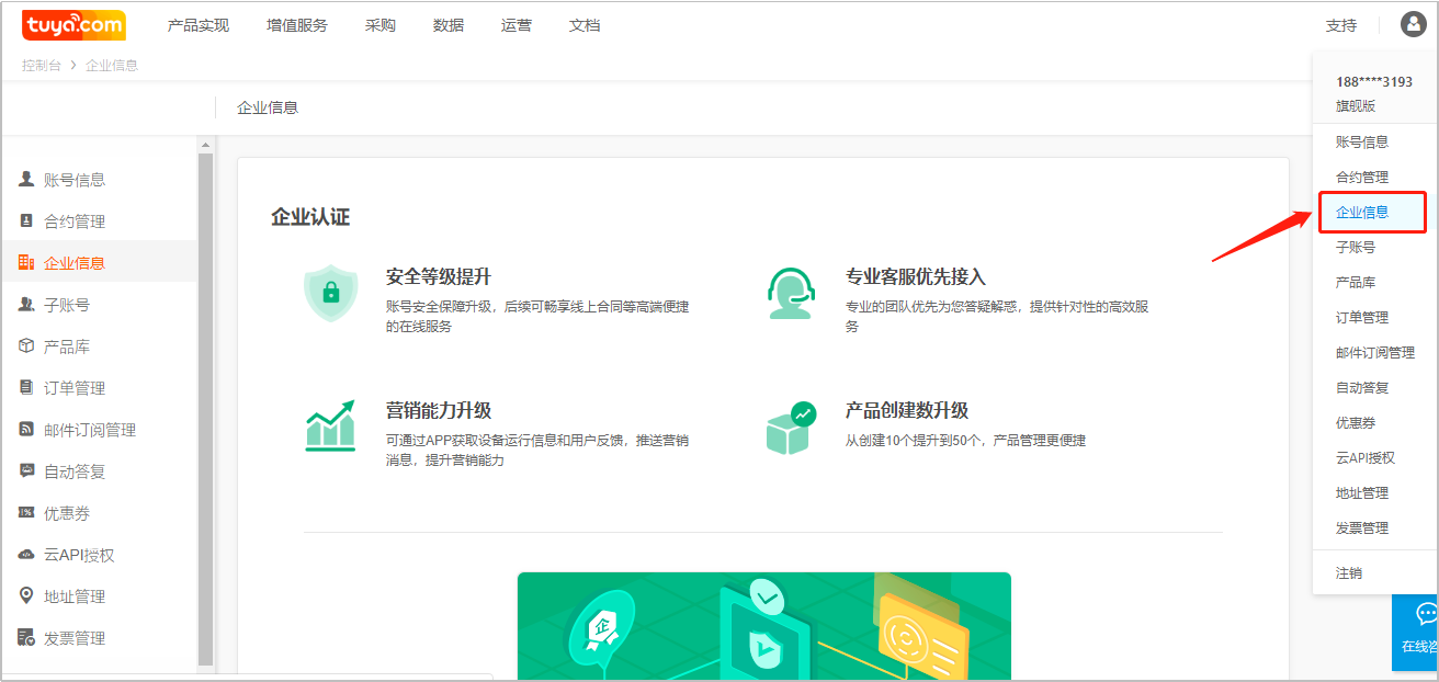
1. Register and log in the Tuya IoT platform (iot.tuya.com). 2. It is suggested to complete the enterprise certification at the same time.
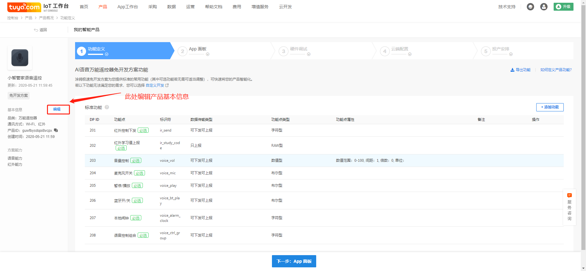
### Create AI voice infrared remote control products
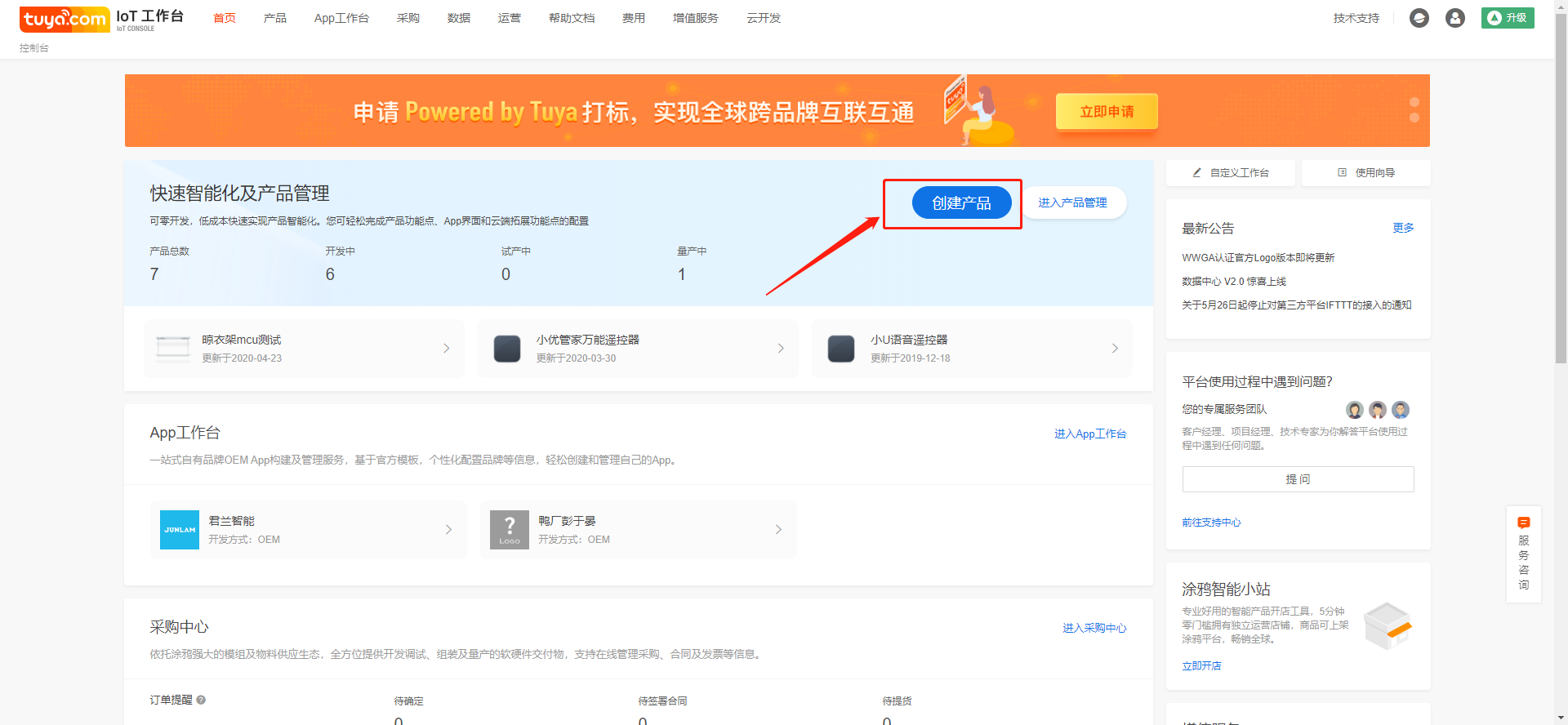
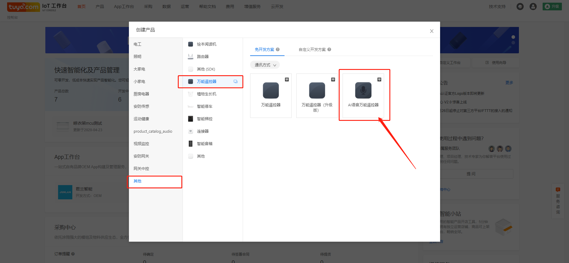
1. Click create product
2. In the "other" category, select "AI voice universal remote control "in" universal remote control ".
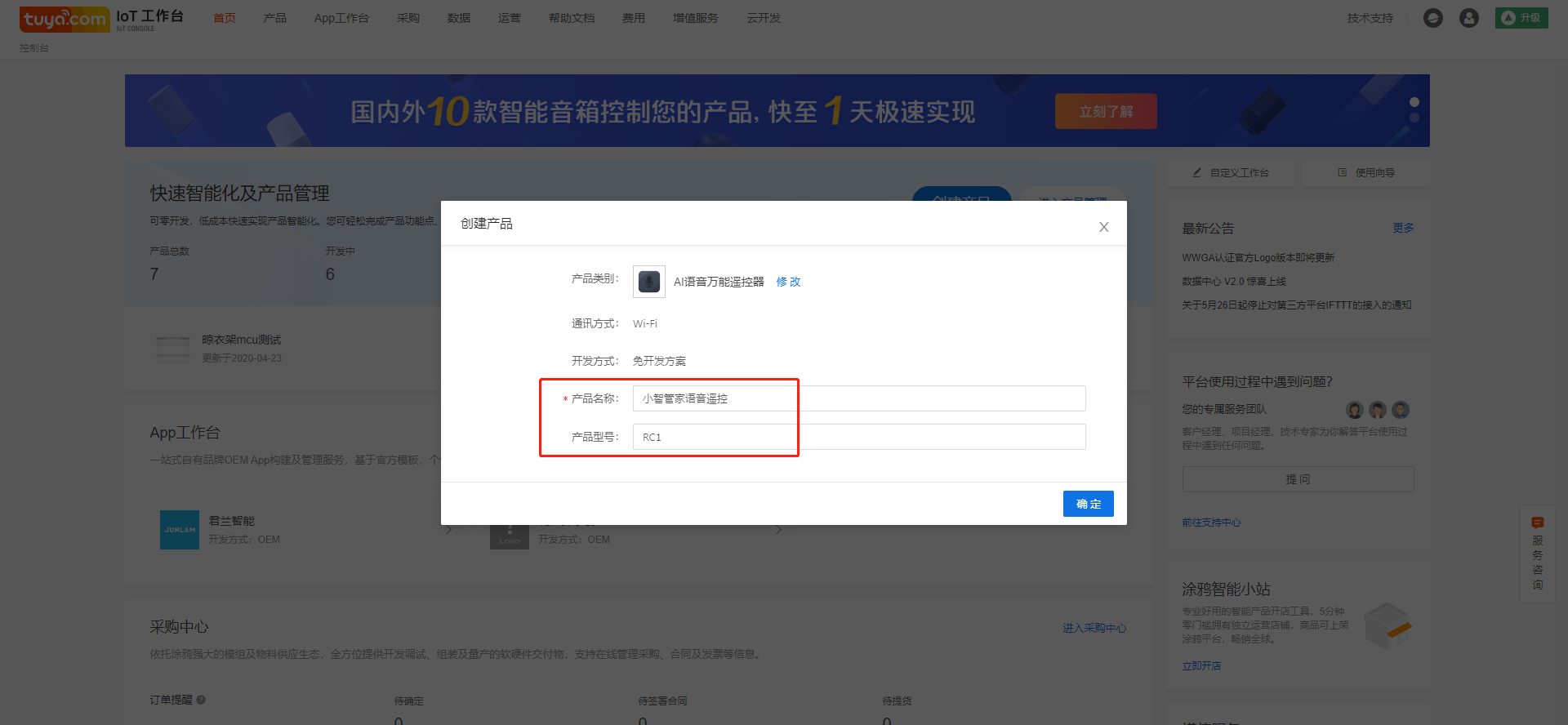
1. Fill in the product name, which will be displayed on the App control interface
2. Product model. It is recommended to fill in the internal model name or customer product model to facilitate product maintenance and order management.
3. The above information can be modified in "edit product information".
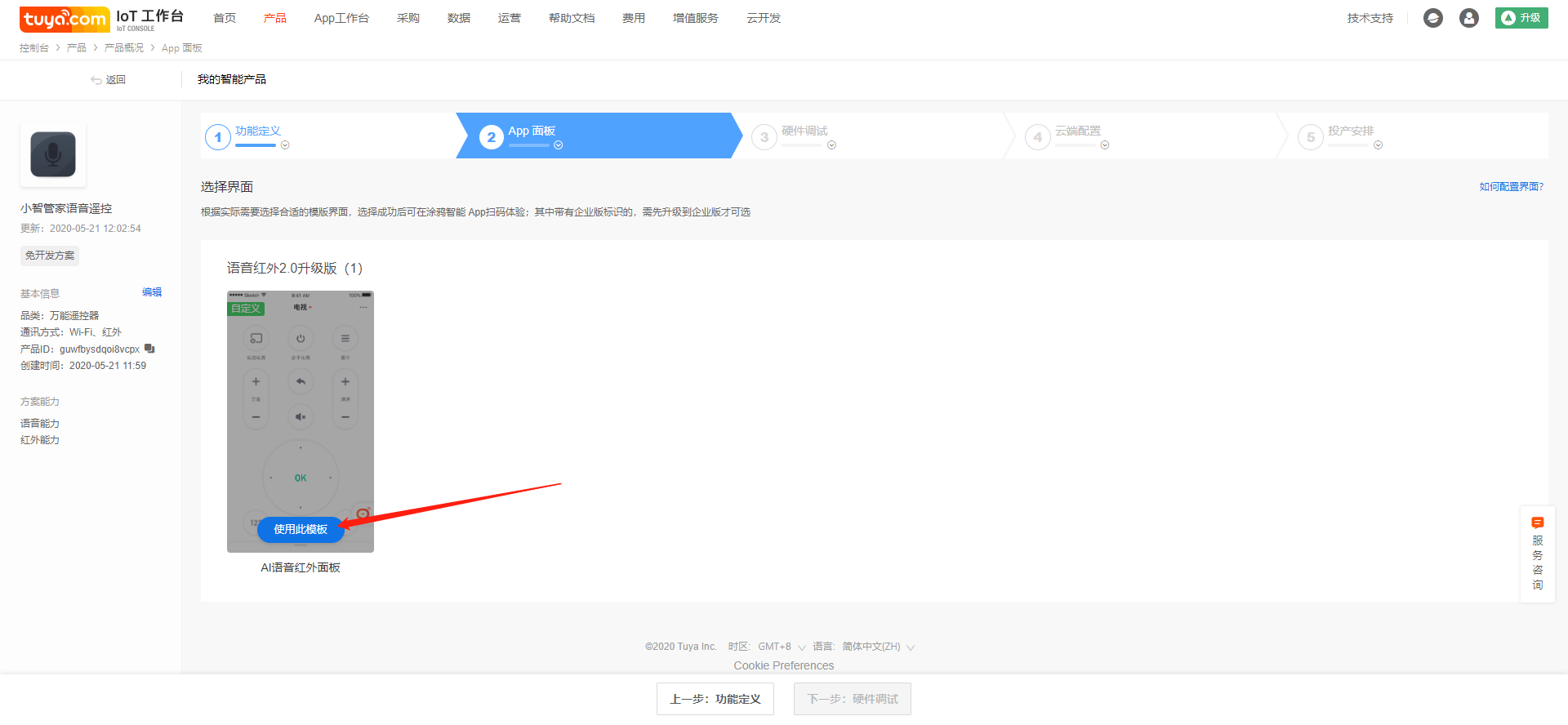
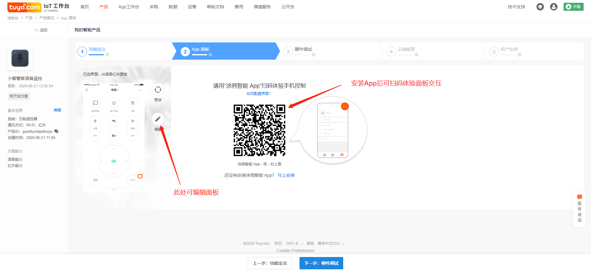
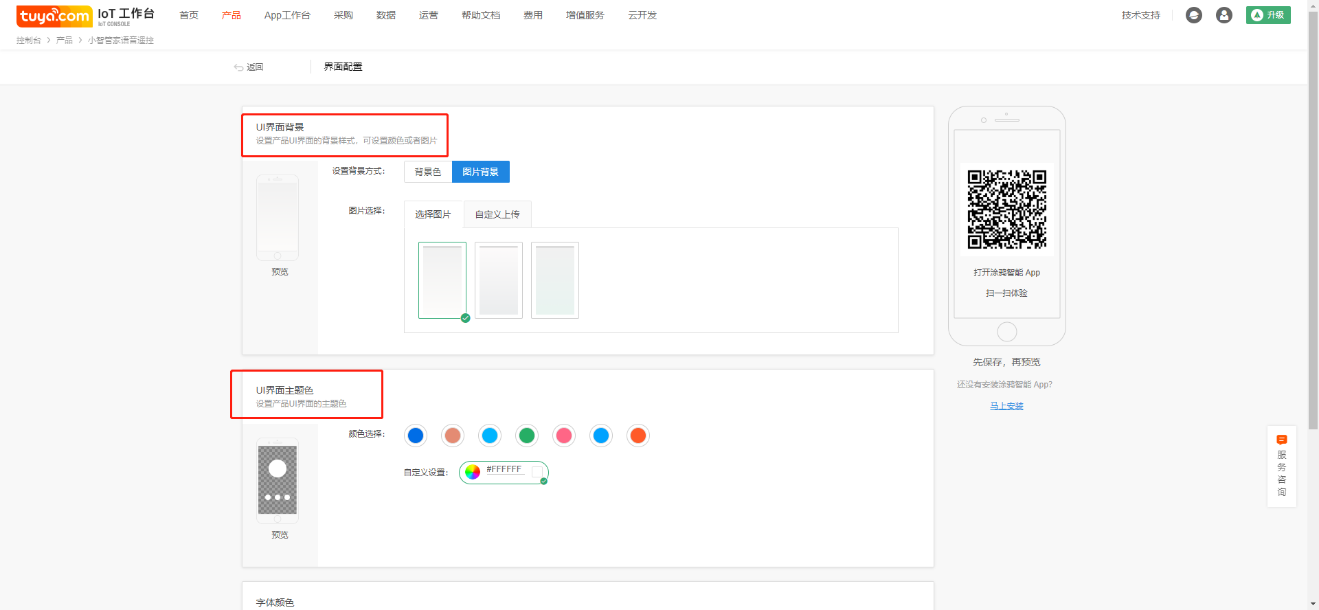
### Configure App panel
1. Select the App control panel;
2. After confirming the control panel, you can experience the interaction of the control panel in the App through the function of scribbling intelligence or scanning code in the intelligent living App;
3. Select the custom panel to enter the panel editing interface and modify the panel color matching and background.
### Hardware debugging
Let's take the VWXR2 module as an example to explain the configuration instructions
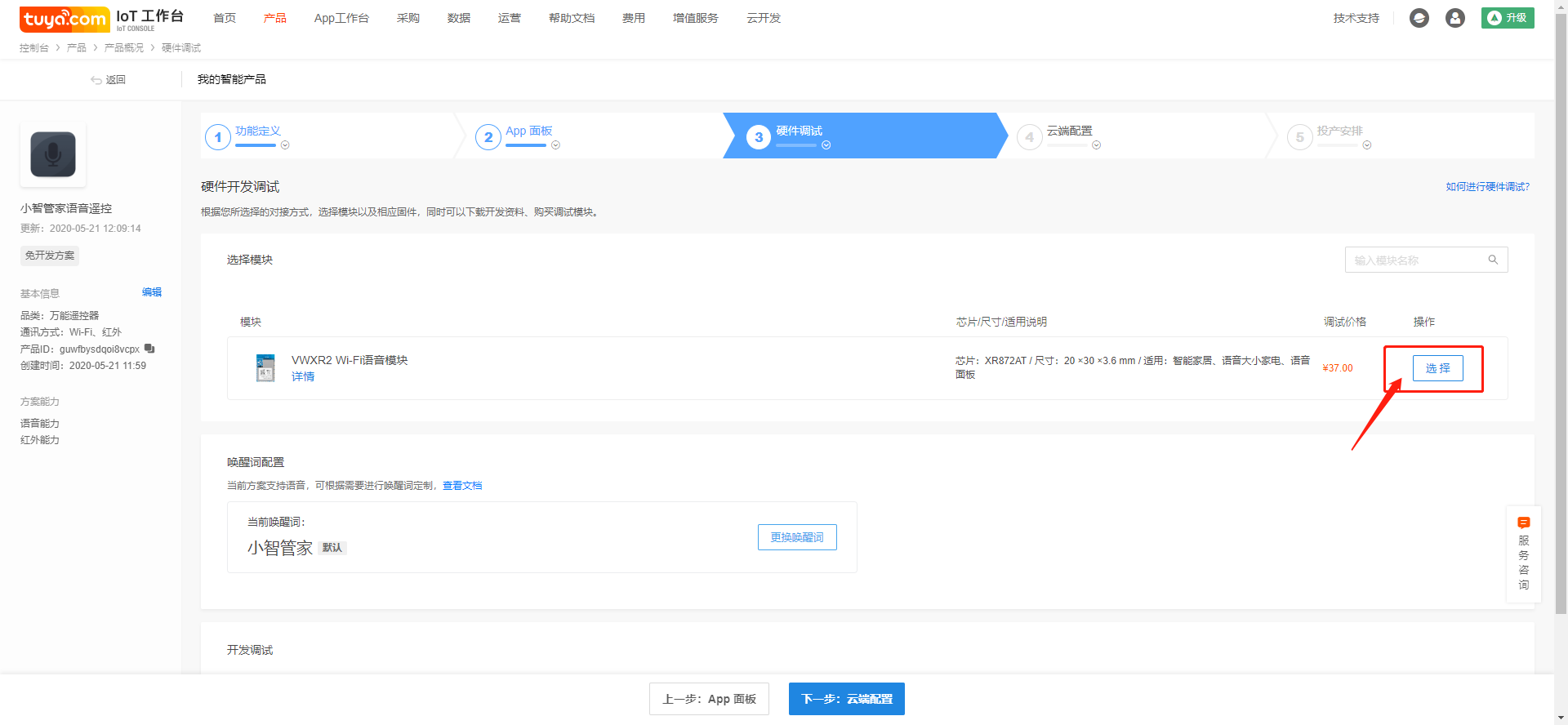1. Select the VWXR2 module and enter the firmware configuration interface;
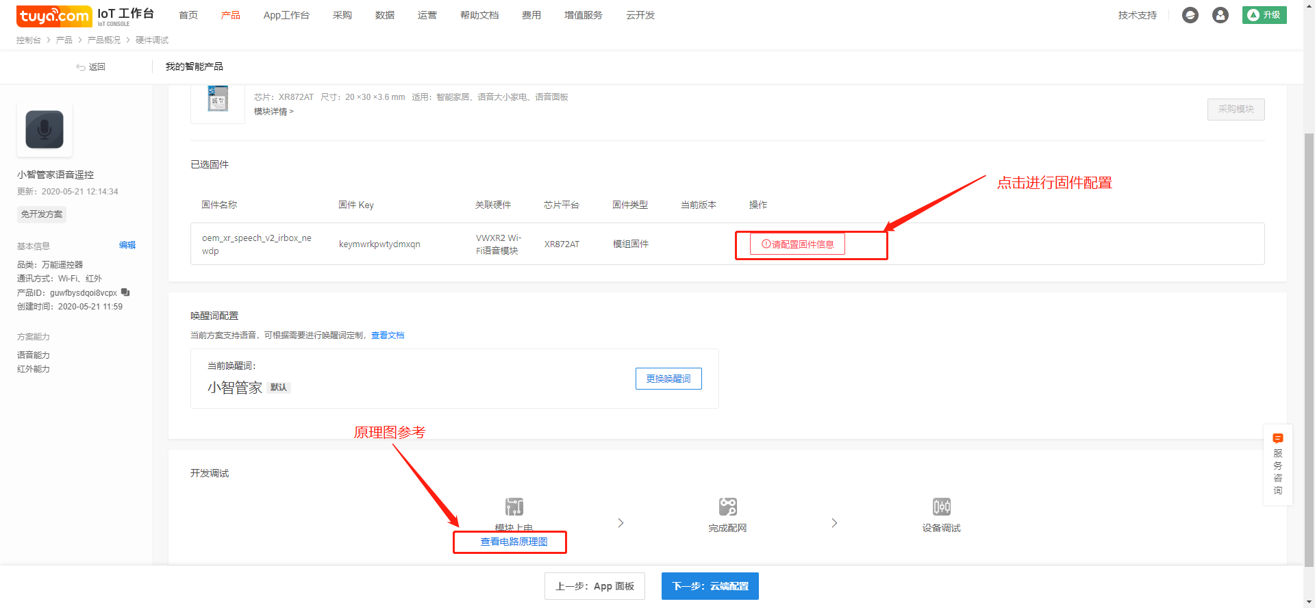
1. Click configure firmware information to configure firmware;
2. Click the schematic diagram below to view the scheme reference schematic diagram;
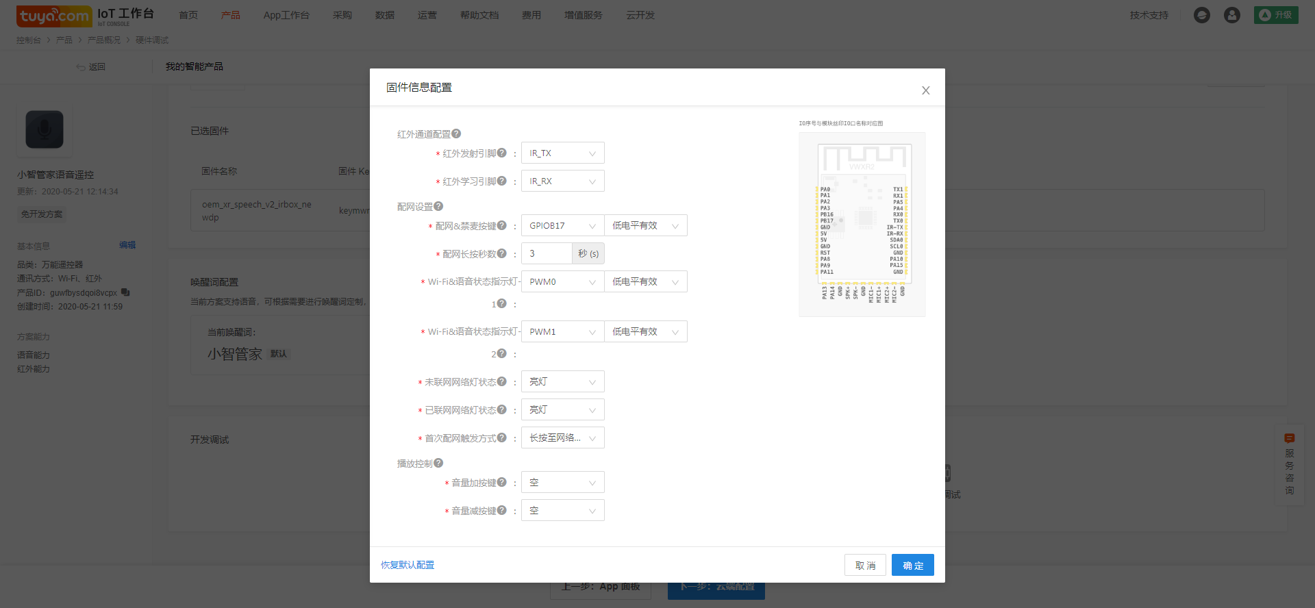
1. Infrared channel setting:
The module pins for infrared transmission and infrared reception are set here in The VWXR2 module has a special infrared transceiver pin, which is the default
Fixed as IR\_TX and IR\_RX pins, not configured as other pins.
1. Network configuration
Configuration of MIC keys:
The voice infrared distribution network button is equipped with the anti-mic function. Short press the button to switch the MIC switch, and long press to enter the distribution network mode
b. distribution network length per second:
Configure the long button press time to enter the distribution mode;
c. indicator 1& indicator 2 configuration:
voice infrared scheme supports dual color indicator, dual color indicator is not only used for the distribution network prompt, but also for the voice control lamp
Light feedback, the following is the light feedback logic configured by default (indicator 1 is configured with red, indicator 2 is configured with blue) :
Product status light prompt
Default distribution network mode: red and blue alternate flash;
Compatible distribution network mode: red and blue alternating slow flash;
Off state: red light breathing;
It has been awakened and the network is working normally.
Has been awakened but the network is abnormal: from extinguished to red light on;
Recognition: blue light breathing;
No recording is allowed (press the distribution network button to switch the MIC switch) : the red light is always on
IoT device control success: the blue light stays on for 2S;
IoT device control failure: red light constantly on 2S
Normal standby mode: the indicator light is off
d. Trigger mode of the first distribution network
There are two ways for users to enter the distribution network when using the product for the first time: one is to enter the distribution network state when power is on, and the other is to enter the distribution network state when long press the distribution network button.
1. Play control
Volume button configuration, this is an advanced option, do not need to use the volume of the product, select empty.
Note: click on the save the configuration and after sending module, has been sending module in IO and features shall not be able to modify. If you find the hardware schematic diagram and the IO you choose does not exist and you need to modify it, please re-save the configuration and send the module again. Send module IO and new features will work with new save configuration. Therefore, please before you choose the configuration and design circuit principle diagram of hardware engineer confirmed IO configuration information, in case of wrong configuration module failure.
## Voice IR design guide
### Structural design reference:
参考[语音模组声学结构设计参考](https://docs.tuya.com/zh/iot/device-development/access-mode-product-solution/voice-products/design-reference-materialsdomestic-voice-module/speech-module-reference-for-acoustic-structure-design-of-product-design?id=K9hhl5myc7393),
Special reminder: the opening spacing of the microphone is ≥40mm, and 60MM is recommended
\##Hardware design reference:
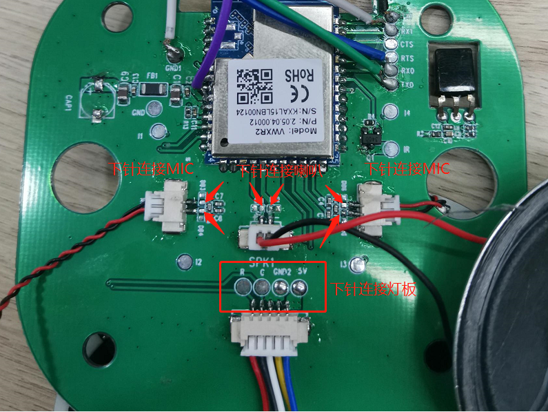
1、For design references such as power supply design, MIC selection and MIC circuit, SPK selection and SPK circuit, ESD and TDD protection design, and module antenna location, please refer to: [hardware design guide for voice module VWXR2](https://docs.tuya.com/zh/iot/device-development/access-mode-product-solution/voice-products/design-reference-materialsdomestic-voice-module/audio-module-vwxr2-hardware-design-guide?id=K9hhnh8en866b)
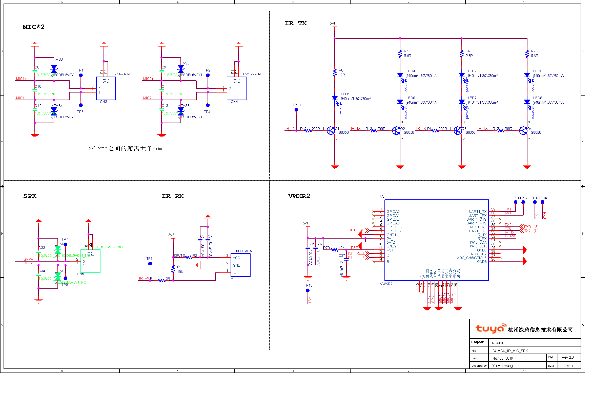
2、The following figure is the speech infrared reference schematic diagram developed based on the VWXR2 module:
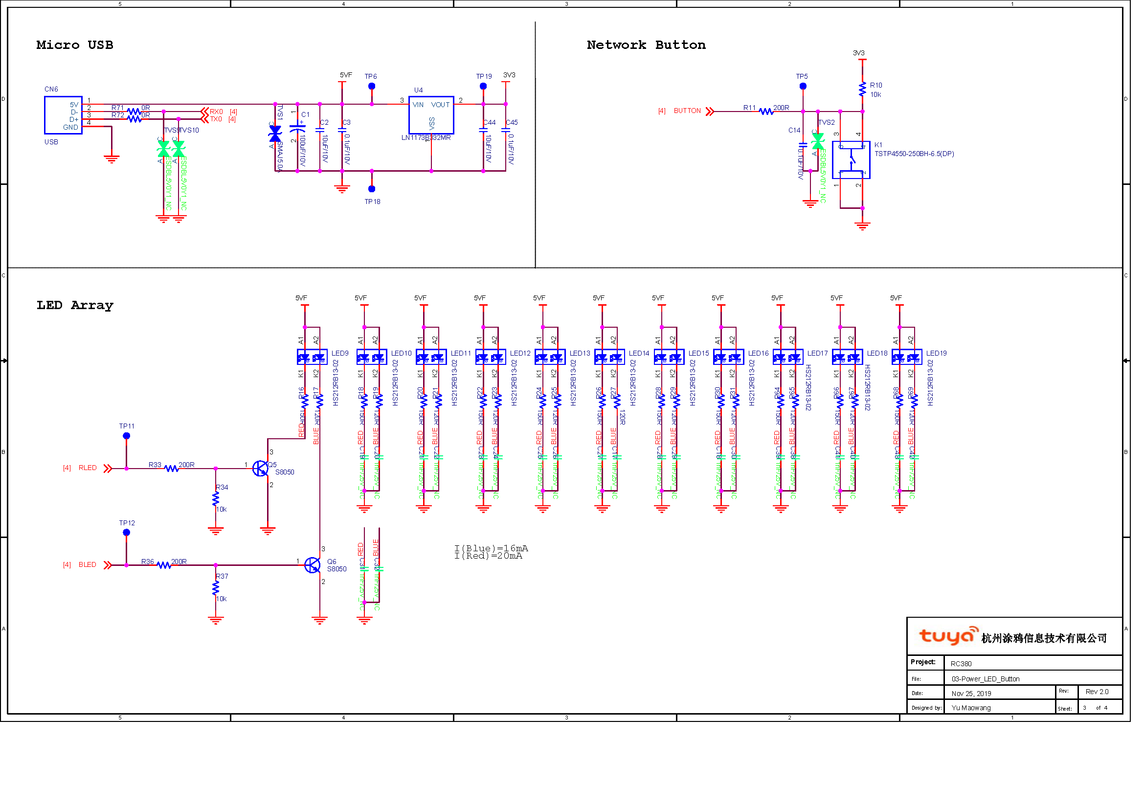3. Place the filter capacitor as close to the IC power pin as possible;
1. The infrared transmitting tube is evenly distributed. It is recommended to put one perpendicular to the PCB and one at 60 ° intervals (45 \~ 60 ° from the PCB plane) on the periphery.
2. It is recommended that the package of transmitting tube current-limiting resistance should be no less than 0805;
3. The spherical part of the front receiving head should avoid direct light as far as possible, and the receiving head with strong anti-interference ability should be selected. LF0038KAHA of lanfeng is recommended.
4. If you want to design light feedback as a voice state indicator, it is suggested to design LED array, otherwise a single LED can be designed to reduce the cost. The disadvantage is that there is no light feedback in voice control;
4, TX0, RX0 as production and test communication serial port to USB, avoid reuse and reserve test points, in addition, VCC and GND also reserve test points, convenient firmware burning and authorization;
1. The projection area of the module antenna is recommended to be completely hollow out. The distance of the antenna from the shell is guaranteed to be > 1mm to guarantee the antenna performance.
2. The infrared light transmittance of the shell directly affects the control distance of the whole machine. It is suggested that the infrared light transmittance of the shell material is > 80%;
## Test guide for Voice IR
### Objective:
Infrared remote control function test operation instructions, to facilitate customers to complete product testing.
### The scope of:
Voice infrared remote control products
### Solution platform installation:
1. Test tool preparation:
Test tooling, test equipment
Wireless router
Computer (Internet connection required)
Test camera with camera obscure-box and infrared detection function (normal android phone is ok)
Special USB cable \*2: production method \[take the graffiti serial port board +USB cable (cut the USB head), then connect the serial port board 5V/GND/TX/RX with the USB cable, pay attention to TX, RX do not connect the reverse, the welding is completed]
2Solution platform installation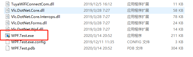
Double-click the diagram to start the production test tool
Install the serial driver
According to the computer system and serial port installation, it is recommended to use CP2102 serial port, figure 1 is win10 64 system driver, figure 2 is win7 64 system driver.
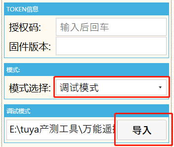
### Solution platform operation instructions:
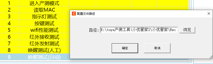
1.Open the solution platform tool. Select debug mode and import the json file (test series file) to find the corresponding path.
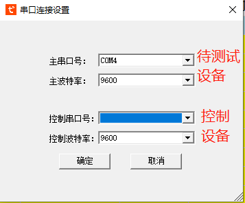
2.Click start test and double click to establish the connection line. Set the serial port (the main serial port is set for the test). Double-click the wake up test to automatically import the audio file (note the audio file format wav format). The awakening words are: "little wise steward"
3.Enter the SN number and click "run" to power the device. The remote control enters the production and test mode automatically. Check the flashing indicator manually click ok, the indicator does not flash and click failed. Pass the test to the next step. Key test, touch the key test pass will automatically jump to the next step.
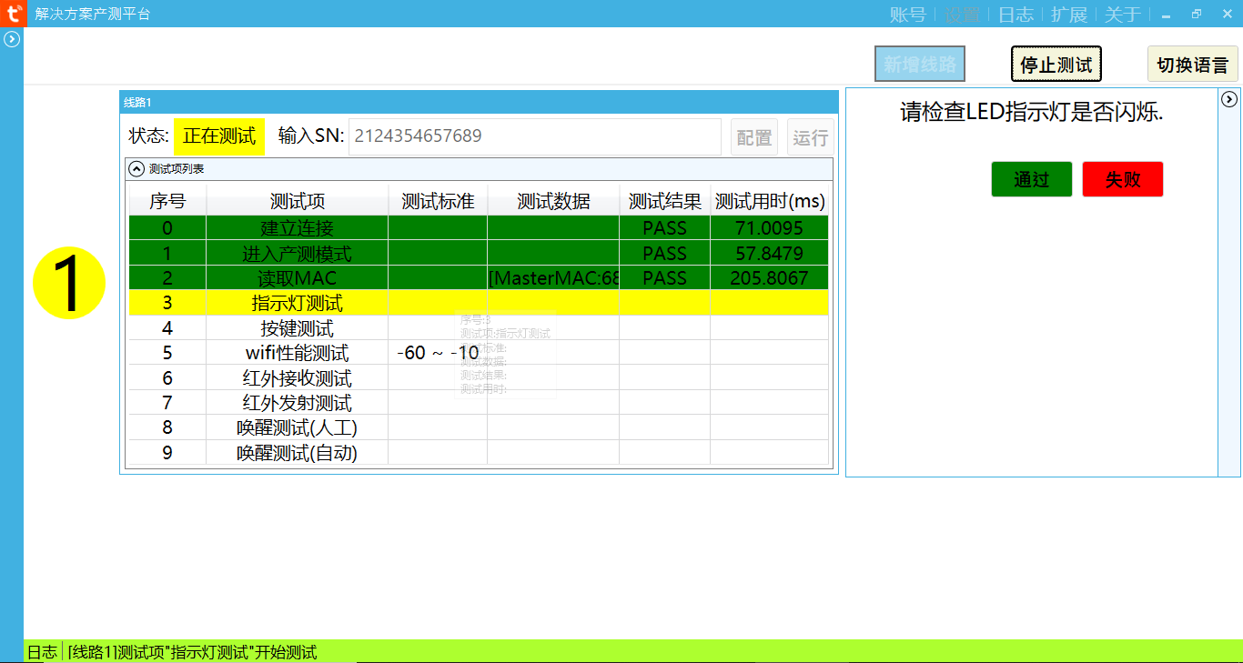
Wifi performance test: the router with SSID of tuya\_mdev\_test1 needs to be set and placed 3-5 meters away from the product under test. When the module receives the router's signal strength at -60db-10db, it is qualified. Test pass to automatically modulate the next step, and test fail to stop the test.
For infrared transmission and reception test, the distance between the two devices is suggested to be about 1m. Test pass automatically takes the next step, and test fail stops.
Manual awakening test: manual awakening of "little wisdom butler" to equipment
Automatic wake test: play the voice file to automatically wake the device.
MIC and trumpet test: manual recording and broadcasting, manual speaking a word casually, and loudspeaker playing a manual voice recording.
### Test rack manufacturing instructions:
#### Production instructions for PCBA test rack:
1. It is suggested that the button should face up to facilitate employees to test the button.
2. PCBA power supply serial port power supply to USB interface to lamp board to PCBA motherboard for testing.
USB 5 v -- -- -- -- -- -- -- -- -- -- -- -- -- -- -- -- -- -- 5 v serial port
GND -- -- -- -- -- -- -- -- -- -- -- -- -- -- -- - GND
TX -- -- -- -- -- -- -- -- -- -- -- -- -- -- -- -- -- RX
RX -- -- -- -- -- -- -- -- -- -- -- -- -- -- -- -- -- the TX
1. Test rack for the whole machine: connect the computer and the tested machine with the serial port to USB power supply line mentioned above
· infrared lamp test:
The observation of infrared lamp in production is not obvious and the testing efficiency is low. It is recommended that the finished product should be tested separately for aging test.
Use a camera to take pictures and observe in a dark environment.
1. The router with the starting SSID of tuya\_mdev\_test1.
2. Power on the finished product.
3. When the module is swept to tuya\_mdev\_test1, it will automatically enter the finished product production test mode. At this point refers to the red and blue indicator light cycle flashing 6 times.
The infrared indicator continues to flash at intervals of 1 second.
1. Use the camera to take pictures and observe whether the four infrared lights are flashing.