> For the complete documentation index, see [llms.txt](https://docs.ifreeq.com/llms.txt). Markdown versions of documentation pages are available by appending `.md` to page URLs; this page is available as [Markdown](https://docs.ifreeq.com/developer/device-development/access-mode-mcu/zigbee-general-solution/hardware-design.md).
# Hardware Design
## TYZS3 Module & MCU serial communication instructions
### Typical Application diagram
Diagram 1 MCU(3.3V) & Module cooperative processing mode
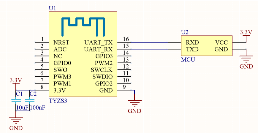
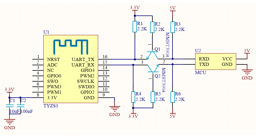
Diagram 2 MCU(5V) & Module cooperative processing mode
!
### Design specification
1.The module is under the condition of 250Kbps rate and + 19dBm transmit power, power supply consumption: 3.3V, the typical current is about 120mA. Proposed supply current≥300mA. 2. Power filter capacitor C1 & C2 should be distributed as close to the 3.3V pin as possible.C1 & C2≥10uF. 3. RESET pin is module hardware reset pin, effective under the low level. Without external circuitry, it can be directly connected to the IO port of MCU for use.
## TYZS5 Module & MCU serial communication instructions
### Typical Application diagram
Diagram 1 MCU(3.3V) & Module cooperative processing mode
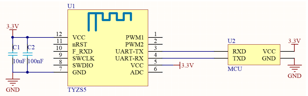
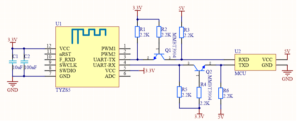
Diagram 2 MCU(5V) & Module cooperative processing mode
### Design specification
1.The module is under the condition of 250Kbps rate and + 19dBm transmit power, power supply consumption: 3.3V, the typical current is about 118mA. Proposed supply current≥300mA. 2. Power filter capacitor C1 & C2 should be distributed as close to the 3.3V pin as possible.C1 & C2≥10uF. 3. RESET pin is module hardware reset pin, effective under the low level. Without external circuitry, it can be directly connected to the IO port of MCU for use.
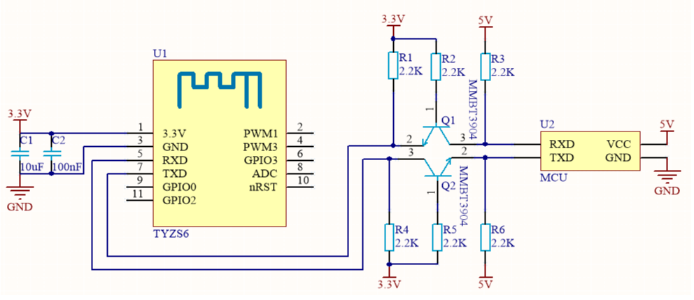
## TYZS6 Module & MCU serial communication instructions
### Typical Application diagram
Diagram 1 MCU(3.3V) & Module cooperative processing mode
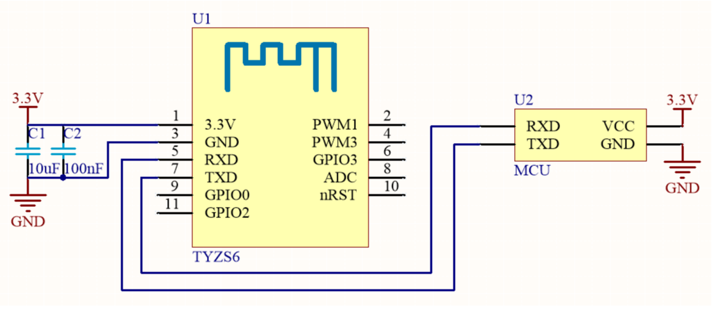
Diagram 2 MCU(5V) & Module cooperative processing mode
### Design specification
1.In working mode,power supply consumption: 3.3V, the typical current is about 40mA. Proposed supply current≥100mA. 2. Power filter capacitor C1 & C2 should be distributed as close to the 3.3V pin as possible.C1 & C2≥10uF. 3. nRST pin is module hardware reset pin, effective under the low level. Without external circuitry, it can be directly connected to the IO port of MCU for use.
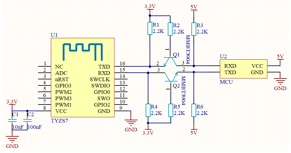
## TYZS7 Module & MCU serial communication instructions
### Typical Application diagram
Diagram 1 MCU(3.3V) & Module cooperative processing mode
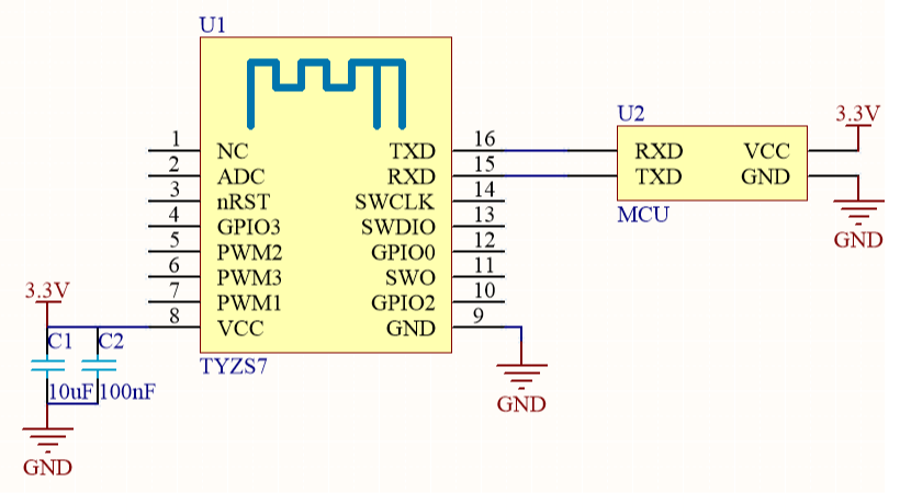
Diagram 2 MCU(5V) & Module cooperative processing mode
### Design specification
1.The module is under the condition of 250Kbps rate and + 19dBm transmit power, power supply consumption: 3.3V, the typical current is about 118mA. Proposed supply current≥300mA. 2. Power filter capacitor C1 & C2 should be distributed as close to the 3.3V pin as possible.C1 & C2≥10uF. 3. nRST pin is module hardware reset pin, effective under the low level. Without external circuitry, it can be directly connected to the IO port of MCU for use.
## TYZS8 Module & MCU serial communication instructions
### Typical Application diagram
Diagram 1 MCU(3.3V) & Module cooperative processing mode
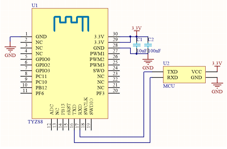
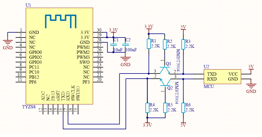
Diagram 2 MCU(5V) & Module cooperative processing mode
### Design specification
1.The module is under the condition of 250Kbps rate and + 19dBm transmit power, power supply consumption: 3.3V, the typical current is about 120mA. Proposed supply current≥300mA. 2. Power filter capacitor C1 & C2 should be distributed as close to the 3.3V pin as possible.C1 & C2≥10uF. 3. nRST pin is module hardware reset pin, effective under the low level. Without external circuitry, it can be directly connected to the IO port of MCU for use.
## TYZS10 Module & MCU serial communication instructions
\## Typical Application diagram
Diagram 1 MCU(3.3V) & Module cooperative processing mode
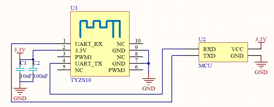
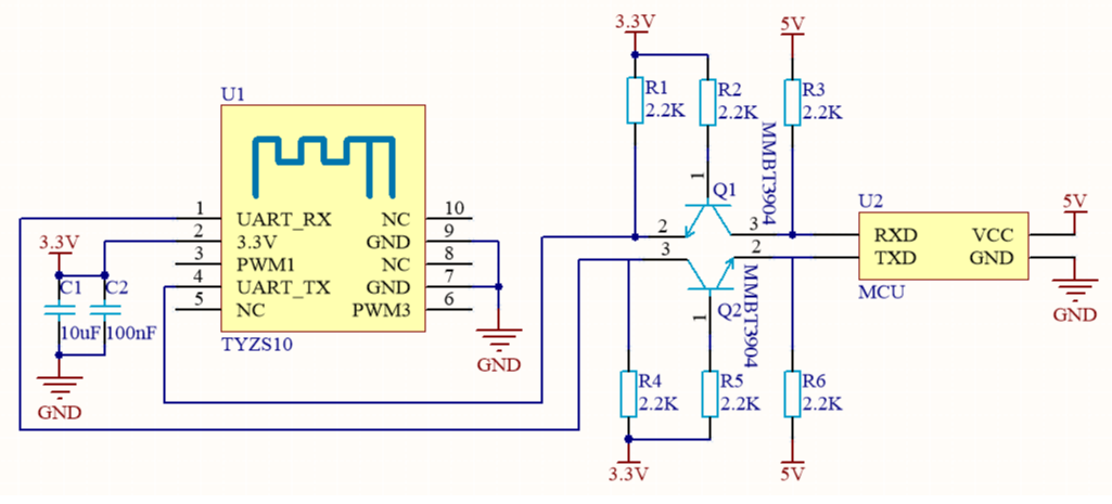
Diagram 2 MCU(5V) & Module cooperative processing mode
### Design specification
1.The module is under the condition of 250Kbps rate and + 19dBm transmit power, power supply consumption: 3.3V, the typical current is about 120mA. Proposed supply current≥300mA. 2. Power filter capacitor C1 & C2 should be distributed as close to the 3.3V pin as possible.C1 & C2≥10uF.
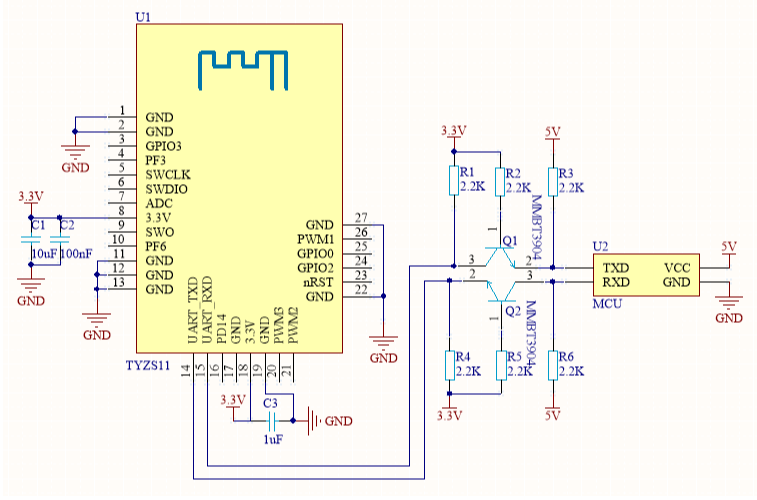
## TYZS11 Module & MCU serial communication instructions
### Typical Application diagram
Diagram 1 MCU(3.3V) & Module cooperative processing mode
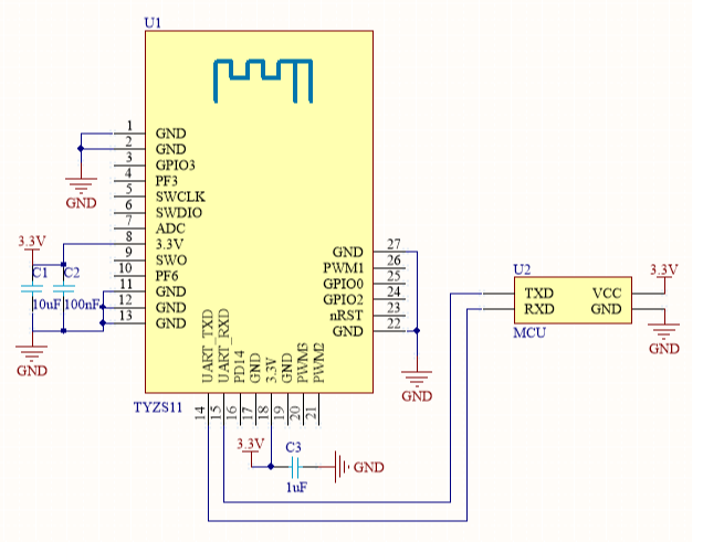
Diagram 2 MCU(5V) & Module cooperative processing mode
### Design specification
1.The module is under the condition of 250Kbps rate and + 19dBm transmit power, power supply consumption: 3.3V, the typical current is about 120mA. Proposed supply current≥300mA. 2. Power filter capacitor C1 & C2 should be distributed as close to the 3.3V pin as possible.C1 & C2≥10uF. 3. nRST pin is module hardware reset pin, effective under the low level. Without external circuitry, it can be directly connected to the IO port of MCU for use.
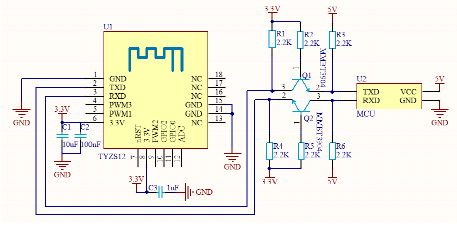
## TYZS12 Module & MCU serial communication instructions
### Typical Application diagram
Diagram 1 MCU(3.3V) & Module cooperative processing mode
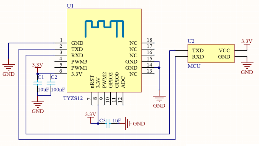
Diagram 2 MCU(5V) & Module cooperative processing mode
### Design specification
1.The module is under the condition of 250Kbps rate and + 19dBm transmit power, power supply consumption: 3.3V, the typical current is about 120mA. Proposed supply current≥300mA. 2. Power filter capacitor C1 & C2 should be distributed as close to the 3.3V pin as possible.C1 & C2≥10uF. 3. nRST pin is module hardware reset pin, effective under the low level. Without external circuitry, it can be directly connected to the IO port of MCU for use.
## TYZS13 Module & MCU serial communication instructions
### Typical Application diagram
Diagram 1 MCU(3.3V) & Module cooperative processing mode
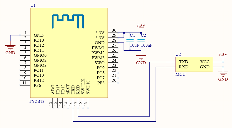
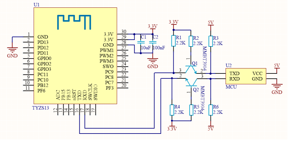
Diagram 2 MCU(5V) & Module cooperative processing mode
### Design specification
1.The module is under the condition of 250Kbps rate and + 19dBm transmit power, power supply consumption: 3.3V, the typical current is about 120mA. Proposed supply current≥300mA. 2. Power filter capacitor C1 & C2 should be distributed as close to the 3.3V pin as possible.C1 & C2≥10uF. 3. nRST pin is module hardware reset pin, effective under the low level. Without external circuitry, it can be directly connected to the IO port of MCU for use.