> For the complete documentation index, see [llms.txt](https://docs.ifreeq.com/llms.txt). Markdown versions of documentation pages are available by appending `.md` to page URLs; this page is available as [Markdown](https://docs.ifreeq.com/developer/smart-product-solution/lock/zigbee-lock.md).
# Zigbee Lock
## Universal Docking Agreement
### 1. \*Introduction\*
The Tuya Zigbee serial port general protocol is a Tuya customorize Zigbee module serial port general protocol, which is mainly used for Tuya Zigbee module, it directly connected to other MCU serial ports for serial communication. Its block diagram is shown in Figure 1 below.

### 1.1 \*Hardware connection\*
The Tuya Zigbee module and MCU control both use DC 3.3V power supply.
The baud rate of UART communication between Tuya Zigbee module and MCU is 115200-8-N-1, and there is no data flow control. The UART interface pins use the standard logic. In the idle state, the TXD and RXD pins are both high level, the low level is the start bit and the high level is the stop bit. The pin stays high even even the device in hibernation.
There is a GPIO port reserved between the Tuya Zigbee module and the MCU, use as the module to wake up the MCU. The default setting is the internal pull-up state, which is effective when pulled down to 10ms. The MCU wakes up the Zigbee module by waking up the serial command. If the device is a strong current device, the MCU only needs to make a handshake connection when the device is powered on for the first time. If the device is a weak current device with dormant, apart from making a handshake connection when power on, the MCU needs to connect to the handshake connection before each active command is initiated.
#### \*1.2 Timeout definition\*
#### 1.2.1 \*Synchronization Timeout\*
UART respond timeout time:500ms.
When the serial port of the module receives the wake-up frame of the MCU or the response frame of the wake-up frame, it will wake itself up for 500ms. At this time, the MCU can send other data. If the data interval between the two frames is 500ms, a wake-up frame needs to be added in the middle.
#### 1.2.2 \*Wake-up frame response timeout time\*
After the module sends the wake-up frame, the MCU needs to respond within 20ms, otherwise the module will continue to resend it, twice each time. When the response frame of MCU is not received after 3 transmissions, the data to be transmitted will be stored in the transmission queue, and wait for the next wake up to send again.
### 2. \*Serial port communication\*
### 2.1 \*Frame format\*
The UART communication data frame between the Tuya Zigbee module and the MCU consists of the frame header (Front), version (Ver), serial number (Seq), command word (Cmd), data length (Length), data (Data) and checksum (Check) composition, definition and description are shown below. 2
| Octets:2 | 1 | 2 | 1 | 2 | Variable | 1 |
| -------- | --- | --- | --- | ------ | -------- | ----- |
| Front | Ver | Seq | Cmd | Length | Data | Check |
### 2.2 \*Frame format description\*
| Field | description |
| ------------------- | ----------------------------------------------------------------------------------------------- |
| Front frame(Front) | 2 byte leading character, fixed to 0x55aa |
| Version (Ver) | Serial communication protocol version, for upgrading and expansion, the current version is 0x03 |
| Serial number(Seq) | The serial number(1\~0xfff0) |
| Command (Cmd) | The specific frame type, pls check sheet3 |
| Data length(Length) | Transmitted effective data length |
| Data (Data) | Transmitted effective data |
| Revise (Check) | Data revise, byte-to-byte summation from the beginning of the frame, more than 256 |
Sheet 1:Frame format description
Note: The serial number (seq) is to check each frame. It is not necessary to use the same one. The range of seq is limited to (1 \~ 0xfff0). When the MCU needs to respond to the data sent by the module, the seq in the response frame uses the seq issued by the module. When the MCU needs to send data to the module actively, each time the data is issued, the seq needs to be incremented within the specified range.
| Cmd ID | description | direction |
| -------------------------------------------------------- | --------------------------------------------------------------- | -------------- |
| 0x00 | Dormant wake up | (Zigbee<—>mcu) |
| Wake up response | (mcu<—>zigbee) | |
| 0x01 | Product info check | (zigbee—>mcu) |
| Product info response | (mcu—>zigbee) | |
| 0x02 | Zigbee status inquire | (mcu—>zigbee) |
| Zigbee status inquire response | (zigbee—>mcu) | |
| 0x03 | Zigbee device reset | (mcu—>zigbee) |
| Zigbee device reset response | (zigbee—>mcu) | |
| 0x04 | Data instruction issued | (zigbee—>mcu) |
| Data instruction issued response | (mcu—>zigbee) | |
| 0x05 | Data report | (mcu—>zigbee) |
| Data report response | (zigbee—>mcu) | |
| 0x06 | Zigbee status notice | (zigbee—>mcu) |
| 0x07 | Request dynamic password | (mcu—>zigbee) |
| Request a dynamic password response | (zigbee—>mcu) | |
| 0x23 | Record-type status reporting Data format (including time stamp) | (mcu—>zigbee) |
| Response to data format for record-type status reporting | (zigbee—>mcu) | |
| 0x24 | Mcu time synchronization request | (mcu—>zigbee) |
| Time synchronization request | (zigbee<—>mcu) | |
Sheet 2:Cmd description sheet
Description:
1. All data larger than 1 byte is transmitted in big-endian mode
2. In general, the command word one send and one receive synchronization mechanism is adopted, that is, one party sends a command and the other responds. If the sender does not receive the correct response packet after timeout, the transmission timeout

Note: The specific communication method is subject to the “detailed protocol”
1. The module control command is issued and the MCU status is reported in asynchronous mode. Assuming that the module control command is issued with the "command word" as x and the MCU status is reported with the "command word" as y, as shown below:
1\) Module control command is issued:

2\) MCU status report:
MCU status reporting is divided into two cases: passive reporting and active reporting;
I. Passive reporting: The module sends a data command to the MCU. The MCU responds to the control command first, and then executes the command. The MCU reports the final result to the module. After receiving the module, it sends a response and the data exchange ends.

II. Proactive reporting: MCU status changes (physical operation or restart after power cut, etc.), reporting the current status to the module actively; MCU actively reporting as asynchronous operation, there is no status report response frame received within the timeout period, or the status of the response frame is unsuccessful, MCU must retransmit.

### \*2.3 datapoint Data unit format\*
1\) datapoint The command / status data unit is as follows:
| Data | longth(byte) | description | |
| ------ | --------------- | ----------------------------------------------------------------------------------------------------------------------------- | -------------------------------------------------------------- |
| Dpid | 1 | Datapoint serial number | |
| Type | 1 | Corresponds to the specific data type of a datapoint on the open platform, identified by the following "representation value" | |
| type | Expressed value | length(byte) | explanation |
| raw | 0x00 | N | Corresponds to raw datapoint (module transparent transmission) |
| bool | 0x01 | 1 | Value range:0x00/0x01 |
| value | 0x02 | 4 | Corresponding int type,大端表示 |
| string | 0x03 | N | Corresponds to a specific string |
| enum | 0x04 | 1 | Enumerated type,range 0-255 |
| bitmap | 0x05 | 1/2/4 | When the length is greater than 1 byte,大端表示 |
| Len | 2 | Length corresponding number of bytes | |
| Value | 1/2/4/N | Hex means,Big-endian transmission should be used if more than 1 byte | |
2\) Except for the "raw" type, the datapoint command / status data unit all belongs to the "obj" type datapoint.
3\) The "command issuance" may include multiple datapoint "command data units".
4\) "Command issuance" is an asynchronous processing protocol, corresponding to the "status report" of the MCU's datapoint.
### 3. \*Protocol details\*
### 3.1 \*Wake up command\*
Description:
Zigbee wakes MCU or MCU wakes zigbee with this command
This command will be resent 3 times until a response package is received. After being awakened, it will start to accept data. The maximum time for accepting is one second, and it will go sleep mode after more than 1 second.
This instruction is preceded by 7 BYTE preambles.
Module transmission:
| Word | length(byte) | explanation |
| ------------------ | ------------ | -------------------------------------------------------------------------------- |
| Frame head | 2 | 0x55aa |
| version | 1 | 0x03 |
| Serial number(Seq) | 2 | 55AA(固定序列号) |
| Command word | 1 | 0x00 |
| Data length | 2 | 0x0000 |
| Check the sum | 1 | Byte-by-byte sum from the beginning of the frame,the result is remainder of 256. |
| | | |
MCU return:
| Word | length(byte) | explanation |
| ------------------ | ------------ | ------------------------------------------------------------------------------- |
| Frame head | 2 | 0x55aa |
| Version | 1 | 0x03 |
| Serial number(Seq) | 2 | 55AA(fix serial number) |
| Command word | 1 | 0x00 |
| Data length | 2 | 0 |
| Check the sum | 1 | Byte-by-byte sum from the beginning of the frame,the result is remainder of 256 |
Note: When the module actively wakes up the MCU, the serial number is fixed at 55 AA, and the ACK number returned by the MCU is also 55 AA;
When the MCU actively wakes up the module, the serial number is fixed at 00 00, and the module's ACK serial number returned by the MCU is also 00 00;
example:
1、Module wake up MCU:
Note: When the module actively wakes up the MCU, the serial number is fixed at 55 AA, and the ACK number returned by the MCU is also 55 AA;
When the MCU actively wakes up the module, the serial number is fixed at 00 00, and the module's ACK serial number returned by the MCU is also 00 00;
example:
1. The module wakes up the MCU:
**Module send:**
0x00 00 00 00 00 00 00 55 AA 03 55 AA 00 00 00 01
Leading code *frame head version Seq command word data length checksum*
**MCU reply:**
0x55 AA 03 55 AA 00 00 00 01
*frame head version Seq command word data length checksum*
2、MCU wake up module:
**MCU send:**
0x00 00 00 00 00 00 00 55 AA 03 00 00 00 00 00 02
Leading code *frame head version Seq command word data length checksum*
**Module reply:**
0x55 AA 03 00 00 00 00 00 02
*frame head version Seq command word data length checksum*
### 3.2 \*Check product info\*
Explanation:
1\) product ID: Corresponds to the Tuya Developer Platform PID (Product Identification), which is generated by the Tuya Cloud Developer Platform and is used to record product related information in the cloud.
2\) Product information consists of product ID and MCU software version.
3\) MCU software version number format definition: in dotted decimal form, "x.x.x" (0 <= x <= 99), x is a decimal number.
Module send:
| Word | length(byte) | explanation |
| ------------------ | ------------ | ------------------------------------------------------------------------------- |
| Frame head | 2 | 0x55aa |
| Version | 1 | 0x03 |
| Serial number(Seq) | 2 | In order |
| Command word | 1 | 0x01 |
| Data length | 2 | 0x0000 |
| Data | 0 | no |
| Check the sum | 1 | Byte-by-byte sum from the beginning of the frame,the result is remainder of 256 |
Example:0x55 AA 03 33 77 01 00 00 AD
Frame head ***\*version Seq command word data length check sum\****
MCU return:
| Word | length(byte) | explanation |
| ------------------ | ------------ | ------------------------------------------------------------------------------- |
| Frame head | 2 | 0x55aa |
| Version | 1 | 0x03 |
| Serial number(Seq) | 2 | The module issued seq |
| Command word | 1 | 0x01 |
| Data length | 2 | N |
| Data | N | {“p”:”AIp08kLI”,“v”:”1.0.0” } |
| Data | 1 | Support OTA or not, 1 support,0 not support |
| Check sum | 1 | Byte-by-byte sum from the beginning of the frame,the result is remainder of 256 |
Example:0x55 AA 03 33 77 01 00 1C 7B 22 70 22 3A 22 38 73 34 75 71 75 79 78 22 2C
Frame head ***\*version Seq command word data length { " p " : " 8 s 4 u q u y x " ,\****
22 76 22 3A 22 31 2E 30 2E 30 22 7D 01 7F
***\*" v " : " 1 . 0 . 0 " } check sum\****
P means product ID is 8s4uquyx
V means MCUversion is 1.0.0
Support OTA
### 3.3 \*Check the module network status\*
| Device status ID | Description |
| ---------------- | --------------------------------------------------------------------- |
| 0x00 | Device is not connected to the gateway |
| 0x01 | Device connected to the gateway |
| 0x02 | Device is entered server |
| 0x03 | The device is connected to the gateway and entered the server |
| 0x04 | Device is not connected to the sever |
| 0x05 | The device is connected to the gateway but has not entered the server |
| 0x10 | Transmission report successful |
| 0x20 | Transmission report fail |
| 0x40 | Transmission report timeout |
| 0x80 | Transmission report busy |
Picture 4 module status sheet(8421)
explanation:
1\) The device is not connected to the network: When the device is powered on for the first time, or fails to connect to the network, or is disconnected from the network, the device status is not connected to the network, this status will send to MCU.
2\) The device is in the networked status: After the device is successfully connected to the network, the device is in the networked status; the status is sent to the MCU.
3\) When the module detects the process of MCU restart or MCU disconnect then online again, it will actively send the module network status to the MCU.
4\) When the network status of the module changes, it will actively send the network status of the module to the MCU.
MCU sends
| Word | length(byte) | explanation |
| ------------------ | ------------ | ------------------------------------------------------------------------------- |
| Frame head | 2 | 0x55aa |
| Version | 1 | 0x03 |
| Serial number(Seq) | 2 | MCU effects |
| Command word | 1 | 0x02 |
| Word length | 2 | 0x0000 |
| Data | 0 | no |
| Check sum | 1 | Byte-by-byte sum from the beginning of the frame,the result is remainder of 256 |
example: 0x55 AA 03 00 00 02 00 00 04
Frame head ***\*version Seq command word data length check sum\****
Module return:
| word | Length (byte) | description |
| ------------------ | ------------- | ------------------------------------------------------------------------------- |
| Frame head | 2 | 0x55aa |
| Version | 1 | 0x03 |
| Serial number(Seq) | 2 | MCU send SEQ |
| Command word | 1 | 0x02 |
| Data length | 2 | 0x0001 |
| Data | 1 | Indicate module working status:Zigbee status,check picture 4 |
| Check sum | 1 | Byte-by-byte sum from the beginning of the frame,the result is remainder of 256 |
例:0x55 AA 03 00 00 02 00 01 03 08
Frame head ***\*version Seq command word data length data check sum\****
### 3.4 \*Configure Zigbee module\*
Description:
1\) If the device is a low-voltage device, the MCU needs to send a wake-up command to the module first, and then send a configuration command to the module; a strong-power device directly sends a configuration command to the module.
a. There are two types of commands for configuring the Zigbee module, as shown in the figure below.
| command | description |
| ------- | ------------------------------------------------------------------------- |
| 0x00 | Reset the module to factory default status (not connected to the network) |
| 0x01 | Configure the module to start network configuration |
MCU send:
| word | length(byte) | description |
| ------------------ | ------------ | ------------------------------------------------------------------------------- |
| Frame head | 2 | 0x55aa |
| version | 1 | 0x03 |
| Serial number(Seq) | 2 | MCU effects |
| Comand word | 1 | 0x03 |
| Data length | 2 | 0x0001 |
| Data | 1 | 0x00/0x01 |
| Check sum | 1 | Byte-by-byte sum from the beginning of the frame,the result is remainder of 256 |
Example:0x55 AA 03 00 00 03 00 01 01 07
Frame head ***\*version Seq command word data length data check sum\****
Module return:
| word | length(byte) | explanation |
| ------------------ | ------------ | ------------------------------------------------------------------------------- |
| Frame head | 2 | 0x55aa |
| version | 1 | 0x03 |
| Serial number(Seq) | 2 | MCU send SEQ |
| Command word | 1 | 0x03 |
| Data length | 2 | 0x0001 |
| data | 1 | 0x00:OK,0x01:error |
| Check sum | 1 | Byte-by-byte sum from the beginning of the frame,the result is remainder of 256 |
example:0x55 AA 03 00 00 03 00 01 00 06
Frame head ***\*version Seq command word data length data check sum\****
### \*3.5 Data Command issued\*
Module send:
| word | length(byte) | explanation |
| ------------------ | ------------ | ------------------------------------------------------------------------------- |
| Frame head | 2 | 0x55aa |
| version | 1 | 0x03 |
| Serial number(Seq) | 2 | Effect in order |
| Comand word | 1 | 0x04 |
| Data length | 2 | Depends on "command data unit" type and number |
| Data | N | “2.3data command unit” |
| Check sum | 1 | Byte-by-byte sum from the beginning of the frame,the result is remainder of 256 |
example:“doorbell select”,
0x55 AA 03 00 1C 04 00 05 0E 04 00 01 00 3A
Frame head ***\*version Seq command word data length dpID dp type data length data check sum\****
mcu返回:
| word | length(byte) | explanation |
| ------------------ | ------------ | ------------------------------------------------------------------------------- |
| Frame head | 2 | 0x55aa |
| version | 1 | 0x03 |
| Serial number(Seq) | 2 | The seq issued by module |
| Comand word | 1 | 0x04 |
| Data length | 2 | 0x0001 |
| Data | 1 | 0x00:OK,0x01:error |
| Check sum | 1 | Byte-by-byte sum from the beginning of the frame,the result is remainder of 256 |
例:0x55 AA 03 00 1C 04 00 01 00 23
Frame head ***\*version Seq command word data length data check sum\****
### \*3.6 MCU data reported\*
Explanation:
1\) After the MCU receives the 04 command, it must reply the 04 command immediately, and the reply is receivingcorrect or failed;
2\) After receiving the 04 instruction successfully, the MCU will process the 04 instruction and send the processed result to the module through the 05 instruction, and inform the module of the 04 instruction execution status;
3\) The module will immediately return ACK to the MCU after receiving the datapoint information of the 05 instruction;
4\) Multiple datapoint "command data units" may be included. For details of the datapoint status data unit, see "Section 2.3", but the data frame length cannot exceed 64 bytes.
MCU send:
| word | length(byte) | explanation |
| ------------------ | ------------ | ------------------------------------------------------------------------------- |
| Frame head | 2 | 0x55aa |
| version | 1 | 0x03 |
| Serial number(Seq) | 2 | MCU effects |
| Comand word | 1 | 0x05 |
| Data length | 2 | Depends on the type and number of "status data unit", including SeqNum and data |
| | N | “2.3status data unit” |
| Check sum | 1 | Byte-by-byte sum from the beginning of the frame,the result is remainder of 256 |
Example:“doorbell ring”,
0x55 AA 03 00 00 05 00 05 0E 01 00 01 01 1D
***\*Frame head version Seq command word data length dpID dp type data length data check sum\****
Module return:
| word | Length (byte) | Explanation |
| ------------------ | ------------- | ------------------------------------------------------------------------------- |
| Frame head | 2 | 0x55aa |
| version | 1 | 0x03 |
| Serial number(Seq) | 2 | MCU send SEQ |
| Comand word | 1 | 0x05 |
| Data length | 2 | 0x0001 |
| Data | 1 | Zigbee status,check picture 4 |
| Check sum | 1 | Byte-by-byte sum from the beginning of the frame,the result is remainder of 256 |
Example:0x55 AA 03 00 00 05 00 01 10 18
Frame head ***\*version Seq command word data length data check sum\****
### \*3.7 Zigbee notice\*
Note: zigbee asynchronous notification or network status change notification
Module sends:
| word | length(byte) | description |
| ------------------ | ------------ | ------------------------------------------------------------------------------- |
| Frame head | 2 | 0x55aa |
| version | 1 | 0x03 |
| Serial number(Seq) | 2 | Effects in order |
| Comand word | 1 | 0x06 |
| Data length | 1 | 0x02 |
| Data | 1 | Zigbee status,check picture 4 |
| Check sum | 1 | Byte-by-byte sum from the beginning of the frame,the result is remainder of 256 |
Example:“network status”effects:
0x55 AA 03 00 77 06 00 01 05 85
Frame head ***\*version Seq command word data length data check sum\****
MCU returns:
| word | length(byte) | explanation |
| ------------------ | ------------ | ------------------------------------------------------------------------------- |
| Frame head | 2 | 0x55aa |
| version | 1 | 0x03 |
| Serial number(Seq) | 2 | Seq issued by module |
| Comand word | 1 | 0x06 |
| Data length | 2 | 0x0001 |
| Data | 1 | Zigbee status,check picture 4 |
| Check sum | 1 | Byte-by-byte sum from the beginning of the frame,the result is remainder of 256 |
Example:“network status”respnse:
0x55 AA 03 00 77 06 00 01 10 90
Frame head ***\*version Seq command word data length data check sum\****
### \*3.8 Requesting a Dynamic Password\*
Note: (1) The time data in the protocol is used to calculate the current dynamic password. The dynamic password calculation time here is the current Green Time. The device needs to give the module Green Time data.
(2)On the APP side, you can set a mixed calculation whether the device currently needs to add the administrator password to the participate dynamic passwords. Every time the device requests to verify the dynamic password again, it needs to lock all the current door of the module. Administrator password.
(3) The data length of the sending package is at least 15 bytes, time data + password + the number of administrator password groups transmitted (not including the optional administrator password).
MCU sends:
| word | length(byte) | explanation |
| ------------------ | ------------ | ----------------------------------------------------------------------------------------------------------------------------------------------------------- |
| Frame head | 2 | 0x55aa |
| version | 1 | 0x03 |
| Serial number(Seq) | 2 | MCU effects |
| Comand word | 1 | 0x07 |
| Data length | 2 | xx xx |
| Data | 4 | Data length is 4bytes: the current device green time: data\[0]-data\[3] |
| | 8 | Password data entered by the user: Data\[4]Data\[11] the data content range‘0’’9’ data transmmit ASCLL code |
| | 1 | The number of administrator password groups (0 \~ 10), numbers of groups of administrator passwords are followed by the corresponding group number data |
| | 1 | The length of the first password (up to 8) |
| | n | The first group of administrator password (the password is composed of numbers) The data content range is ‘0’ \~ ’9’ The data transmission uses ASCLL code |
| | 1 | The length of the second set of passwords (no more than 8) |
| | n | The second group of administrator password (the password is composed of numbers) The data content range is ‘0’ \~ ’9’ The data transmission uses ASCLL code |
| | … | … |
| Check sum | 1 | Byte-by-byte sum from the beginning of the frame,the result is remainder of 256 |
Example:
55 AA 03 00 00 07 00 1D 5B BC 3A 41 33 37 32 32 34 32 30 31 02 Frame head ***\*version Seq command word data length time stamp active password Administrator password numbers\****
06 30 31 32 33 34 35 08
***\*First set of password length The first administrator password Second set of password length\**** 31 32 33 34 35 36 37 38 30
***\*The second set of administrator passwords check sum\****
Module return:
| word | length(byte) | explanation |
| ------------------ | ------------ | --------------------------------------------------------------------------------------------------------------- |
| Frame head | 2 | 0x55aa |
| version | 1 | 0x03 |
| Serial number(Seq) | 2 | MCU issued SEQ |
| Comand word | 1 | 0x07 |
| Data length | 2 | 0x0001 |
| Data | 1 | 0x00(password check successful) 0x01(Password check failed) 0x02(device not get seckey) 0x03(Data length error) |
| Check sum | 1 | Byte-by-byte sum from the beginning of the frame,the result is remainder of 256 |
Example:55 AA 03 00 00 07 00 01 00 0A
Frame head ***\*version Seq command word data length data check sum\****
### \*3.9 Zigbee module functional test\*
Note: The RF test method of the module is performed by loopback test between DUT (equipment under test) and GU (golden unit). That is, the DUT sends packets, and the GU sends the packets to DUT. Perform statistics and report the results to the MCU through the serial port. Round trip time interval is 3S.
1\) Send the production test command within 300ms after power on.
MCU send:
| word | length(byte) | explanation |
| ------------------ | ------------ | ------------------------------------------------------------------------------- |
| Frame head | 2 | 0x55aa |
| version | 1 | 0x03 |
| Serial number(Seq) | 2 | MCU effects |
| Comand word | 1 | 0x09 |
| Data length | 2 | 0x0001 |
| Data | Data | Channel value(11-26) |
| Check sum | 1 | Byte-by-byte sum from the beginning of the frame,the result is remainder of 256 |
Example:0x00 00 00 00 00 00 00 55 AA 03 00 00 09 00 01 19 25
Preamble Frame head ***\*version Seq command word data length data check sum\****
Module return:
| word | Length(byte) | explanation |
| ------------------ | ------------ | ------------------------------------------------------------------------------- |
| Frame head | 2 | 0x55aa |
| version | 1 | 0x03 |
| Serial number(Seq) | 2 | MCU下发的SEQ |
| Comand word | 1 | 0x09 |
| Data length | 2 | 0x0001 |
| Data | 2 | RFreceive0-100%(Suggested success rate80%) |
| Check sum | 1 | Byte-by-byte sum from the beginning of the frame,the result is remainder of 256 |
Example:0x55 AA 03 00 00 09 00 02 01 3C 4A
Frame head ***\*version Seq command word data length data check sum\****
Note:\*\*\*\*:support firmware version:1.0.4\*\*\*\*
### \*3.10\* \*MCU\* \*OTA\*
The MCU ota process is as follow:

\***\******MCU version check\******\***
If MCU upgrade is supported, this command must be implemented, and the MCU can also report actively;
Query scenarios: 1. During network distribution 2. When the MCU upgrade process is abnormal;
Proactive reporting scenarios: 1. After network pairing successful (must be added) 2. Upgrade finished;
Module send:
| word | Length(byte) | explanation |
| ------------------ | ------------ | ------------------------------------------------------------------------------- |
| Frame head | 2 | 0x55aa |
| version | 1 | 0x03 |
| Serial number(Seq) | 2 | Module effects |
| Comand word | 1 | 0x0A |
| Data length | 2 | 0x0000 |
| Data | 0 | |
| Check sum | 1 | Byte-by-byte sum from the beginning of the frame,the result is remainder of 256 |
Example:0x55 AA 03 00 f0 0A 00 00 26
Frame head ***\*version Seq command word data length check sum\****
MCU response or module send:
| word | Length(byte) | explanation |
| ------------------ | ------------ | ------------------------------------------------------------------------------- |
| Frame head | 2 | 0x55aa |
| version | 1 | 0x03 |
| Serial number(Seq) | 2 | MCU issued SEQ |
| Comand word | 1 | 0x0A |
| Data length | 2 | 0x0001 |
| Data | 1 | Version number (current version)01.00.0001 à1.0.1 |
| Check sum | 1 | Byte-by-byte sum from the beginning of the frame,the result is remainder of 256 |
### \*3.11 OTA update notice\*
Module send
| word | Length(byte) | explanation |
| ------------------ | ------------ | -------------------------------------------------------------------------------------------------- |
| Frame head | 2 | 0x55aa |
| version | 1 | 0x03 |
| Serial number(Seq) | 2 | Module effects |
| Comand word | 1 | 0x0B |
| Data length | 2 | 0x000F |
| Data | 8 | Data\[0]\~ Data\[7] PID |
| Data | 1 | Version number (update version)01.00.0001 à1.0.1 |
| Data | 4 | Firmwware size at most 64K |
| Data | 4 | Firmware checksum:Byte-by-byte sum from the beginning of the frame,the result is remainder of 2^32 |
| Check sum | 1 | Byte-by-byte sum from the beginning of the frame,the result is remainder of 256 |
Example:0x55 AA 03 00 1C 0B 00 0F 30 31 32 33 34 35 36 37 41
Frame head ***\*version Seq command word data length PID V\****
MCU corresponding:
| word | Length(byte) | explanation |
| ------------------ | ------------ | ------------------------------------------------------------------------------- |
| Frame head | 2 | 0x55aa |
| version | 1 | 0x03 |
| Serial number(Seq) | 2 | Module issued seq |
| Comand word | 1 | 0x0B |
| Data length | 2 | 0x0001 |
| Data | 1 | 0x00:OK,0x01:error |
| Check sum | 1 | Byte-by-byte sum from the beginning of the frame,the result is remainder of 256 |
Example:0x55 AA 03 00 1C 0B 00 01 00 23
Frame head ***\*version Seq command word data length data check sum\****
### \*3.12 OTA firmware content requests\*
MCU send:
| word | Length(byte) | explanation |
| ------------------ | ------------ | ------------------------------------------------------------------------------- |
| Frame head | 2 | 0x55aa |
| version | 1 | 0x03 |
| Serial number(Seq) | 2 | 0x0000 |
| Comand word | 1 | 0x0C |
| Data length | 2 | 0x0006 |
| Data | 8 | PID |
| Data | 1 | Version number (update version) 01.00.0001 à1.0.1 |
| Data | 4 | Offset of data package (location of firmware) |
| Data | 1 | Data package size |
| Checksum | 1 | Byte-by-byte sum from the beginning of the frame,the result is remainder of 256 |
Example:0x55 AA 03 00 f0 0C 00 06 26
Frame head ***\*version Seq command word data length checksum\****
Module corresponding:
| word | length(byte) | explanation |
| ------------------ | ------------ | ------------------------------------------------------------------------------- |
| Frame head | 2 | 0x55aa |
| version | 1 | 0x03 |
| Serial number(Seq) | 2 | 0x0000 |
| Comand word | 1 | 0x0C |
| Data length | 6+N | 0x0006+N |
| Data | 1 | Status 0 succeed 1:fail |
| Data | 8 | PID |
| Data | 1 | Version number (update version) 01.00.0001 à1.0.1 |
| Data | 4 | Offset of data package (location of firmware) |
| Data | N | Data |
| checksum | 1 | Byte-by-byte sum from the beginning of the frame,the result is remainder of 256 |
Example:
55 AA 03 00 39 24 00 08 00 00 0D 2B 00 00 7D AB C7
Frame head ***\*version Seq command word data length standard time\**** ***\*local time check sum\****
### \*3.13 OTA firmware upgrade result report\*
Note: This result is reported after the MCU upgrade is completed; no matter whether the MCU upgrade is successful or failed, as long as the upgrade action is initiated, the upgrade process must be terminated through the result report command;
MCU sends:
| word | Length(byte) | explanation |
| ------------------ | ------------ | ------------------------------------------------------------------------------- |
| Frame head | 2 | 0x55aa |
| version | 1 | 0x03 |
| Serial number(Seq) | 2 | MCU issued SEQ |
| Comand word | 1 | 0x0D |
| Data length | 2 | 0x0004 |
| Data | 1 | Status 0 succeed 1:fail |
| Data | 8 | PID |
| Data | 1 | Version number (update version) 01.00.0001 à1.0.1 |
| Checksum | 1 | Byte-by-byte sum from the beginning of the frame,the result is remainder of 256 |
Example:
0x55 AA 03 00 f0 0C 00 06 26
Frame head ***\*version Seq command word data length checksum\****
Module corresponding:
| word | Length(byte) | explanation |
| ------------------ | ------------ | ------------------------------------------------------------------------------- |
| Frame head | 2 | 0x55aa |
| version | 1 | 0x03 |
| Serial number(Seq) | 2 | MCU下发的SEQ |
| Comand word | 1 | 0x0D |
| Data length | 2 | 0x0001 |
| Data | 1 | 0x00:OK,0x01:error |
| Check sum | 1 | Byte-by-byte sum from the beginning of the frame,the result is remainder of 256 |
Example:0x55 AA 03 00 1C 0D 00 01 00 23
Frame head ***\*version Seq command word data length data checksum\****
### \*3.14 Data format for record-type status reporting (including time stamp)\*
Explanation:
1\) When the MCU data changes , such as various door opening actions, various alarm information, local password changes, etc., which involves the local operation of the door lock, the door lock MCU needs to use this command to send the corresponding DP data to the module;
2\) When reporting the frame data, the frame needs to carry a time stamp. If the MCU has time data locally, the time stamp needs to be included in the data;
3\) Multiple datapoint "command data units" can be included. For details of the datapoint status data unit, see "Section 2.3", but the data frame length cannot exceed 64 bytes.
MCUsend:
| word | Length(byte) | explanation |
| ------------------ | ------------------ | -------------------------------------------------------------------------------------------------------------- |
| Frame head | 2 | 0x55aa |
| version | 1 | 0x03 |
| Serial number(Seq) | 2 | MCU effects |
| Comand word | 1 | 0x23 |
| Data length | 2 | Depends on the type and number of "status data unit" |
| Data | 5 | Data\[0]: whether use mcu time or not0:use gateway time1:Time reported using mcuData\[1]\~ Data\[4] time stamp |
| N | “Status data unit” | |
| Checksum | 1 | Byte-by-byte sum from the beginning of the frame,the result is remainder of 256 |
Example:“Fingerprint unlock”:
0x55 AA 03 00 00 23 00 0D 01 5B F6 67 B1 01 02
Frame head ***\*version Seq command word data length MCU time time stamp dpID dp type\****
00 04 00 00 00 0B AE
***\*data length data checksum\****
“Password + fingerprint combination unlock”:
0x55 AA 03 00 00 23 00 15 00 5B F6 67 B1 02
Frame head ***\*version Seq command word data length gateway time time stamp dpID(password)\****
02 00 04 00 00 00 01 01 02 00 04 00 00 00 05 B8
***\*Dp type data length data dpID(pingerprint) dp type data length data checksum\****
Data return:
| word | Length(byte) | explanation |
| ------------------ | ------------ | ------------------------------------------------------------------------------- |
| Frame head | 2 | 0x55aa |
| version | 1 | 0x03 |
| Serial number(Seq) | 2 | MCU issued SEQ |
| Comand word | 1 | 0x23 |
| Data length | 2 | 0x0001 |
| Data | 1 | Zigbee status,check picture 4 |
| Check sum | 1 | Byte-by-byte sum from the beginning of the frame,the result is remainder of 256 |
Example:0x55 AA 03 00 00 23 00 01 10 36
Frame head ***\*version Seq command word data length\**** data checksum
The data format of the record-type status report includes the record number and the timestamp when the record occurred.
1, timestamp: the timestamp of the record, using the standard timestamp, that is, 00 January 00 10:00 00: 00 GMT (Beijing time 01 January 1970 08: 00 00 00 minutes Total seconds from now
### \*3.15 Time synchronization data format\*
MCU sends:
| word | Length(byte) | Explanation |
| ------------------ | ------------ | ------------------------------------------------------------------------------- |
| Frame head | 2 | 0x55aa |
| version | 1 | 0x03 |
| Serial number(Seq) | 2 | MCU产生 |
| Comand word | 1 | 0x24 |
| Data length | 2 | 0x0000 |
| Data | 0 | |
| Check sum | 1 | Byte-by-byte sum from the beginning of the frame,the result is remainder of 256 |
Example:0x55 AA 03 00 00 24 00 00 26
Frame head ***\*version Seq command word data length check sum\****
Module response or module send:
| word | Length(byte) | Explanation |
| ------------------ | ------------ | --------------------------------------------------------------------------------- |
| Frame head | 2 | 0x55aa |
| version | 1 | 0x03 |
| Serial number(Seq) | 2 | MCU issued SEQ |
| Comand word | 1 | 0x24 |
| Data length | 2 | 0x0008 |
| Data | 8 | Data\[0]\~ Data\[3] is standard time stampData\[4]\~ Data\[7] is local time stamp |
| Check sum | 1 | Byte-by-byte sum from the beginning of the frame,the result is remainder of 256 |
Example:55 AA 03 00 39 24 00 08 00 00 0D 2B 00 00 7D AB C7
Frame head ***\*version Seq command word data length standard time local time checksum\****
\1. MCU-> gateway: MCU requests time synchronization, the data length in the frame head is 0, and MCU can initiate a synchronization request on its own (when the MCU is powered on again or the timing is synchronized)
\2. Gateway-> MCU: The gateway synchronizes the time to the MCU. The data must include the correct standard time stamp and local time stamp.
After the gateway obtains the correct time, and the sub-device enters the network, the gateway will synchronize the time with the MCU
3.The standard time stamp is the total seconds from 00: 00: 00 on January 01, 1970 GMT.
Local time stamp = standard time stamp + seconds between standard time and local time (including time zone and daylight saving time)
\4. MCU àgateway: MCU requests time synchronization, the data length in the frame header is 0, MCU can initiate synchronization request automatically (when MCU is powered on again or timing synchronization time)
\5. Gateway à MCU: The gateway synchronizes the time to the MCU. The data must include the correct standard time stamp and local time stamp.
After the gateway obtains the correct time, and the sub-device enters the network, the gateway will synchronize the time with the MCU
6.The standard time stamp is the total number of seconds from 00: 00: 00 on January 01, 1970, GMT.
Local time stamp = standard time stamp + seconds between standard time and local time (including time zone and daylight saving time)
\7. MCUà gateway: MCU requests time synchronization, the data length in the frame header is 0, MCU can initiate synchronization request automatically (when MCU is powered on again or timing synchronization time)
\8. Gatewayà MCU: The gateway synchronizes the time to the MCU. The data must include the correct standard time stamp and local time stamp.
After the gateway obtains the correct time, and after the sub-device enters the network, the gateway will synchronize the time with the MCU
9.The standard time stamp is the total number of seconds from 00: 00: 00 on January 01, 1970, GMT.
Local time stamp = standard time stamp + seconds between standard time and local time (including time zone and daylight saving time)
Send feedback
History record
### 4. \*DP explanation\*
| ***\*Function Name\**** | ***\*dpid\**** | ***\*Type\**** | ***\*Description\**** | ***\*Mode\**** | ***\*Serial command word\**** | ***\*Data length\**** | ***\*Data Format\**** |
| --------------------------------------------------------------------------------- | ------------------ | -------------- | -------------------------------------------------------------------------------------------------------------------------------------------------------------------------------------------------------------------------------------------------------------------------------------------------------------------------------------------------------------------------------------------------------------------------------------------------------------------------------------------------------------------------------------------------------- | -------------- | ----------------------------- | --------------------- | -------------------------------------------------------------------------------------------------------------------------------------------------------------------------------------------------------------------------------------------------------------------------------------------------------------------------------------------------------------------------------------------------------------------------------------------------------------------------------------------------------------------------------------------------------------------------------------------------------------------------- |
| Fingerprint unlock | 1 | value | The fingerprint is entered on the door lock. After the entry , the ID is assigned by the hardware. After the fingerprint unlocked, the door lock will report the dp point. | Report | 0x23 | 0x04 | {"unit":"","min":0,"max":999,"scale":0,"step":1,"type":"value"} |
| Ordinary Password unlock | 2 | value | The ordinary password is entered on the door lock. After the entry, the ID is assigned by the hardware. After the ordinary password is unlocked, the door lock will report the dp point. The ordinary password refers to the password created on the door lock hardware, and does not include the temporary password created through the app. | Report | 0x23 | 0x04 | {"unit":"","min":0,"max":999,"scale":0,"step":1,"type":"value"} |
| Temporary Password unlock | 3 | value | The temporary password created through the app must be reported after the door is successfully opened using this function type. | Report | 0x23 | 0x04 | {"unit":"","min":0,"max":999,"scale":0,"step":1,"type":"value"} |
| Dynamic password unlock | 4 | value | After the door is successfully opened using the dynamic password, the report is performed, as long as the specified number 1 is reported. When the app displays, as long as there is a dynamic password record, the specific number is not displayed, only the type | Report | 0x23 | 0x04 | {"unit":"","min":0,"max":999,"scale":0,"step":1,"type":"value"} |
| Card unlock | 5 | value | | Report | 0x23 | 0x04 | {"unit":"","min":0,"max":999,"scale":0,"step":1,"type":"value"} |
| Face unlock | 6 | value | | Report | 0x23 | 0x04 | {"unit":"","min":0,"max":999,"scale":0,"step":1,"type":"value"} |
| Mechanical key unlock | 7 | value | | Report | 0x23 | 0x04 | {"unit":"","min":0,"max":999,"scale":0,"step":1,"type":"value"} |
| Door opening and closing events | 8 | bool | If the door lock hardware supports the monitoring of door opening and closing events, select this option. In the door opening record, add the door opening and closing events, and the latest door opening and closing record reflects the current opening and closing status of the door. 0 = close, 1 = open | Report | 0x23 | 0x01 | {"type":"bool"} |
| Alarm | 9 | enum | 1 = Fingerprint trial and error alarm, 2 = Password trial and error alarm, 3 = Card trial and error alarm, 4 = Face trial and error alarm, 5 = False lock (the tongue is stuck), 6 = High temperature alarm, 7 = Do not close the door after timeout , 8 = electronic lock tongue does not pop up, 9 = anti-pry alarm, 10 = key insertion, 11 = low battery alarm; low battery temporarily retains the design of a separate dp point, if the low power alarm value in this dp point is used , Don't use 11dp point. | Report | 0x05 | 0x01 | {"range":\["wrong\_finger","wrong\_password","wrong\_card","wrong\_face","tongue\_bad","too\_hot","unclosed\_time","tongue\_not\_out","pry","key\_in","low\_battery"],"type":"enum"} |
| Remaining battery | 10 | value | Door lock reported power percentage | Report | 0x05 | 0x04 | {"unit":"","min":0,"max":100,"scale":0,"step":1,"type":"value"} |
| Low battery alarm | 11 | Enum | Low power temporarily retains the design of using a separate dp point. If low power alarm in 109dp point is used, do not use this dp point.It is recommended that do not use this dp point if there is no special situation. | | | | {"range":\["normal","low","power\_off"],"type":"enum"} |
| Anti-lock state | 12 | bool | If the door lock can be anti-locked by remote control, the dp point can issue an anti-lock command. When operating through hardware, it will also report the state of the anti-lock to the server to unlock the anti-lock command.If the door lock cannot be anti-locked remotely, this dp point is only used for status display; When anti-locking through hardware, the unlock operation will be reported to the server. | Issue | 0x04 | 0x01 | {"type":"bool"} |
| Report | 0x05 | 0x01 | {"type":"bool"} | | | | |
| Child lock status | 13 | bool | Door locks with child lock function need to check this function. When the status changes, the status value will be reported to the server. | Report | 0x05 | 0x01 | {"type":"bool"} |
| Doorbell call | 14 | bool | Support door lock with doorbell. After button is pressed, the door lock hardware emits a door bell, the app receives a reminder. | Report | 0x05 | 0x01 | {"type":"bool"} |
| Doorbell selection | 15 | enum | Ringtone selection. After the app set the ringtone, if the hardware receives it, the original setting value needs to be returned to the server. If it is set to 5, the hardware will return 5 if the setting is successful, otherwise no return. Doorbell gear can be configured according to actual conditions | Issue | 0x04 | 0x01 | {"range":\["1","2","3","4","5","6","7","8","9"],"type":"enum"} |
| Report | 0x05 | 0x01 | | | | | |
| Doorbell volume | 16 | enum | Set the volume of the door lock. You can uniformly set the sound level of the keypad feedback operation on the door lock hardware. mute = mute, low = low, normal = normal, high = high.Doorbell gear can be configured according to actual conditions After the app set the volume, if the hardware receives it, the original setting value needs to be returned to the server. If it is set to high, the hardware will return high if the setting is successful, otherwise no return. | Issue | 0x04 | 0x01 | {"range":\["mute","low","normal","high"],"type":"enum"} |
| Report | 0x05 | 0x01 | | | | | |
| Door lock language switch | 17 | enum | 1 = Simplified Chinese, 2 = English, 3 = Japanese, 4 = German, 5 = Spanish, 6 = Latin, 7 = French, 8 = Russian, 9 = Italian, 10 = Traditional Chinese, 11 = Korean. After the app set the language, if the hardware receives it, the original setting value needs to be returned to the server. If it is set to 5, the hardware will return 5 if the setting is successful, otherwise no return. | Issue | 0x04 | 0x01 | {"range":\["1","2","3","4","5","6","7","8","9","10","11"],"type":"enum"} |
| Report | 0x05 | 0x01 | | | | | |
| Display welcome word management | 18 | string | Door lock with display, if it supports defining welcome words from the app, enable this dp point | Issue | 0x04 | N | {"type":"string","maxlen":255} |
| Report | 0x05 | N | | | | | |
| Button volume | 19 | enum | From 0 to 9, it means from mute to maximum volume. After the app set the volume, if the hardware receives it, the original setting value needs to be returned to the server. If it is set to 5, the hardware will return 5 if the setting is successful, otherwise no return. | Issue | 0x04 | 0x01 | {"range":\["0","1","2","3","4","5","6","7","8","9"],"type":"enum"} |
| Report | 0x05 | 0x01 | | | | | |
| | | | | | | | |
| Door lock local navigation volume | 20 | enum | From 0 to 9, it means from mute to maximum volume. After the app is set, if the hardware receives it, it needs to return the original set value to the server. If it is set to 5, the hardware setting returns 5 if the setting is successful, and does not return if the setting fails. | Issue | 0x04 | 0x01 | {"range":\["0","1","2","3","4","5","6","7","8","9"],"type":"enum"} |
| report | 0x05 | 0x01 | | | | | |
| Remote open door instruction | 21 | raw | When the door open instruction is issued, the password is verified locally to the door lock, and the door lock is unlocked after the verification. After receiving the dp, the door lock needs to reply 22, if the password is successfully opened, it needs to reply 38, and reply 41 | Issue | 0x04 | 0x06 | Data\[0]- Data\[5] ASCII code corrsponding 6-digit password |
| report | Upload use dpid 22 | | | | | | |
| Remote door open command response | 22 | bool | Report the result of opening the door. The result is reported by the gateway transmit. | report | 0x05 | 0x01 | {"type":"bool"} |
| Disable remote door opening | 23 | bool | Through the app settings, you can disable and enable the remote door opening function. After disabling the remote door opening function, you cannot open the door remotely through the app. The door lock hardware will refuse to perform this operation. The door can be opened remotely after re-enabling. | Issue | 0x04 | 0x01 | {"type":"bool"} |
| report | 0x05 | 0x01 | | | | | |
| Create temporary password | 24 | raw | The app / web initiates the operation, calls the server structure, and the server is converted to a dp point | Issue | 0x04 | 0x15 | Tuya serial number + server serial number + door lock manufacturer number + start time +End time + whether it is a one-time + password.a) tuya serial number: Data \[0], Data \[1]b) Server serial number: Data \[2] Data \[3]c) Door lock manufacturer number: Data \[4] Data \[5], when creating, the value is 0x0 0x0d) Start time: Data \[6] -Data \[9]: standard time stampe) End time: Data \[10] -Data \[13]: standard time stampf) Whether it is one time: Data \[14], 1 means one time password, 0 means it is not one time passwordg) Password: Data \[15]-Data \[20] ASCII code corresponds to 6-digit password |
| report | 0x05 | 0x07 | Tuya serial number + server serial number + door lock manufacturer number + return status1) Content analysis:Tuya serial number: Data \[0], Data \[1]Server serial number: Data \[2], Data \[3]Door lock manufacturer number: Data \[4], Data \[5]Return status: Data \[6], 0: failure 1: success 2: duplicate password 3: password is full | | | | |
| Delete temporary password | 25 | raw | The app / web initiates the operation, calls the server structure, and the server is converted to a dp point | Issue | 0x04 | 0x06 | Tuya serial number + server serial number + door lock manufacturer number Tuya serial number: Data \[0], Data \[1] server serial number: Data \[2], Data \[3] door lock manufacturer number: Data \[4], Data \[5] |
| report | 0x05 | 0x07 | Tuya serial number + server serial number + door lock manufacturer number + return statusTuya serial number: Data \[0], Data \[1]Server serial number: Data \[2], Data \[3]Door lock manufacturer number: Data \[4], Data \[5]Return status: Data \[6], 0: failure 1: success 2: password does not exist | | | | |
| Change temporary password | 26 | raw | The app / web initiates the operation, calls the server structure, and the server is converted to a dp point | Issue | 0x04 | 0x15 | Same format as creating temporary password |
| 上行 | 0x05 | 0x07 | Same format as creating temporary password | | | | |
| Freeze temporary password | 27 | raw | The app / web initiates the operation, calls the server structure, and the server is converted to a dp point | Issue | 0x04 | 0x06 | Same format as creating temporary password |
| report | 0x05 | 0x07 | Same format as creating temporary password | | | | |
| Unfreeze temporary passwords | 28 | raw | aThe app / web initiates the operation, calls the server structure, and the server is converted to a dp point | Issue | 0x04 | 0x06 | Same format as creating temporary password |
| report | 0x05 | 0x07 | Same format as creating temporary password | | | | |
| Create a room key remotely | 29 | raw | | Issue | 0x04 | | |
| report | 0x05 | | | | | | |
| Remotely delete room key | 30 | raw | | Issue | 0x04 | | |
| report | 0x05 | | | | | | |
| Remotely modify your room card | 31 | raw | | Issue | 0x04 | | |
| report | 0x05 | | | | | | |
| Remote Freeze Card | 32 | raw | | Issue | 0x04 | | |
| report | 0x05 | | | | | | |
| Remote unfreeze Card | 33 | raw | | Issue | 0x04 | | |
| report | 0x05 | | | | | | |
| Switch between Single unlock and combinationUnlock | 34 | enum | | Issue | 0x04 | 0x01 | {"range":\["Single","Combination"],"type":"enum"} |
| report | 0x05 | 0x01 | | | | | |
| Hijack alarm | 35 | bool | This function does not require hardware implementation by default, and the door lock does not need to be hijacked. Just mark the unlock id on the app. | report | 0x05 | 0x01 | {"type":"bool"} |
| The door opens from the inside | 36 | bool | If the door lock supports the opening detection of the inner handle, but does not support the detection of the opening / closing action, then use this dp point. Such as the electronic lock body, if the inner door can be detected, the dp can be used to open the door from the internal test, which is reflected in the door opening record. Time when inside door opened, report ture (1) | report | 0x05 | 0x01 | {"type":"bool"} |
| Door was opened | 38 | bool | The dp point means that the door has an unlock event, and it does not mean that the door changes from the closed state to the open state, and the opening and closing state needs to be achieved by 108 dp points. The role of this dp is that users can more easily configure automated configuration on the app. If the door lock can detect inside and outside opening, it is recommended to use 8dp point for linkage; if it cannot detect, it is triggered by the unlock event | report | 0x05 | 0x01 | {"type":"bool"} |
| Clear the door lock temporary password | 39 | raw | When the app restores the door lock to its factory settings, the cloud sends instructions to the door lock, and the door lock clears the local temporary password. If the door lock is restored to factory settings locally and the local temporary password is cleared, the dp point cloud needs to be reported to ensure that the temporary password record in the cloud is consistent with the local one. If the 39 failure is reported when the factory settings are restored locally, you need to report 39 after the next network reconfiguration. | issue | 0x04 | 0x06 | Format is same as deleting temporary password |
| report(issue ACK) | 0x05 | 0x07 | Format is same as deleting temporary password | | | | |
| report(report actively)Note: valid 10 seconds after the module enters the network | 0x23 | 0x07 | Format is same as deleting temporary password | | | | |
| Non-password remote unlock the door | 40 | raw | When using this dp for remote door opening, the app triggers remote door opening without a password, and the door lock is unlocked directly after receiving. The door lock received this dp , need to reply 22, reply 38, reply 41 | issue | 0x04 | 0x00 | |
| report | Report use dpid 22 | | | | | | |
| Remote door unlock record | 41 | value | When the door lock is opened remotely,1.Respond to the successful remote door opening instructionReport Open Door Record2.The report door is opened | report | 0x23 | 0x04 | {"unit":"","min":0,"max":999,"scale":0,"step":1,"type":"value"} |
| Lift up anti-lock | 42 | bool | \[Optional] outside of the door lock, after locking the door, the dp point is reportedAnti-lock = ture, not anti-lock = false | report | 0x23 | 0x01 | {"type":"bool"} |
| SMS notification | 43 | bool | \[Pay-Optional] If the password needs to be notified to the user via SMS after the password is created in the app, please click the dp point; if no SMS is required, please do not tick Note: SMS notification is a paid service, all accounts need to be recharged in advance to enable this function by pid | issue | | 0x01 | {"type":"bool"} |
| Iris unlock | 44 | value | \[Optional] record the iris on the door lock. After the entry is completed, the ID is assigned by the hardware. If unlock by the iris, the door lock will report the dp point. Please report as record | report | 0x23 | 0x04 | {"unit":"","min":0,"max":99,"scale":0,"step":1,"type":"value"} |
| Palm print unlock | 45 | value | Enter the palm print on the door lock. After the entry is completed,The ID is assigned by the hardware. If unlock by palmprint, the door lock will report the dp point. Please report as record | report | 0x23 | 0x04 | {"unit":"","min":0,"max":99,"scale":0,"step":1,"type":"value"} |
| Finger vein unlock | 46 | value | \[Optional] Finger vein unlock is entered on the door lock. After the entry is completed, the ID is assigned by the hardware. If unlock by finger vein, the door lock will report the dp point. Please report as record | report | 0x23 | 0x04 | {"unit":"","min":0,"max":99,"scale":0,"step":1,"type":"value"} |
| Opening and closing state | 47 | enum | \[Optional] Select the function (geomagnetic, gyroscope, etc.) that can judge the door opening and closing status on the door lock hardware. When the status changes, report the corresponding value. When the network is initialized for the first time, it is reported as unknown | report | 0x23 | 0x01 | 枚举范围:unknown,open,closed |
| Set a secret-free remote door opening key | 48 | raw | Current key format is 8 digitsSet a password for remote non-secret door opening. The MCU needs to save the password. The issued remote door opening DP will carry a password. You can determine whether to open the door remotely by comparing the passwords. | issue | 0x04 | 0x15 | Whether it is valid (1byte 0 means invalid, 1 means valid) + member number (2byte) + valid time (4byte) + invalid time (4byte) + password usage (2byte) + password (8byte |
| report | 0x05 | 0x03 | Received successfully (1byte 0 means success 1 means failure) + member number (2byte) | | | | |
| New password-free remote door opening-with key | 49 | raw | Remotely open the door to issue a DP. The issued DP data contains the password under DP48. MCU compares the password to determine whether to open the door. | issue | 0x04 | 0x0b | Door open status (1byte 0 means door closed 1 means door opened) + member number (2byte) + password (8byte) |
| report | 0x05 | 0x03 | Reception status (1byte0 Success1 Failure2 member number does not exist3 Key comparison error) + member number (2byte) | | | | |
| Automatic lock-out switch | 50 | raw | Remotely open the door to issue a DP. The issued DP data contains the password under DP48. MCU compares the password to determine whether to open the door. | issue | 0x04 | 0x0b | Door open status (1byte 0 means door closed 1 means door opened) + member number (2byte) + password (8byte) |
| report | 0x05 | 0x03 | Reception status (1byte0 Success1 Failure2 member number does not exist3 Key comparison error) + member number (2byte) | | | | |
| Automatic lockout delay setting | 51 | value | After the automatic lockout is turned on, manufacturers can set the time period on the iot platform according to their own needs.Timing duration:0x00000000\~0xFFFFFFFF(unit:second)if it is 0,close the “ automatic lockout” | issue | 0x04 | 0x04 | Delay time(4byte 0x00000000\~0xFFFFFFFF) |
| report | 0x05 | 0x04 | Delay time(4byte 0x00000000\~0xFFFFFFFF) | | | | |
| Motor torque | 52 | enum | Motor torque is divided into three gears, customers can choose the grade on the iot platform according to their needs | issue | 0x04 | 0x01 | Torque power(1byte)0x01 low Torque 0x02 middle Torque 0x03 high Torque |
| report | 0x05 | 0x01 | Torque power(1byte)0x01 low Torque 0x02 middle Torque 0x03 high Torque | | | | |
## Functions of smart residential locks
This topic describes how to configure the functions for an electronic smart lock with Zigbee technology, including network interconnection, power usage display, remote control, and so forth. However, the involved protocols and DPs (Data Point) are not mentioned, for more information, see [General Docking Agreement for Zigbee](https://docs.tuya.com/en/iot/device-development/access-mode-product-solution/product-solution-lock/product-solution-lock-zigbee/zigbee-door-lock-universal-docking-agreement?id=K9bjcnh616mg5).
### Change log
| Version | Type | Data | Description |
| ------- | ------ | -------- | ------------------------------------------------------------------------------------------ |
| V1.0.0 | New | 2019.3.4 | The first release. |
| V1.0.1 | Revise | 2020.3.2 | Added how to restore factory settings.
Modified description about remote unlock.
|
### Connect to network
To connect a smart lock to the network, a module can perform that independently without predefined DP.
#### Process
Before pairing a smart lock to the gateway, the gateway device must be connected by using app.
After the smart lock is connected, it transmits data, powers on the module, and waits for the module to return the network state. See the following picture for the connection process.
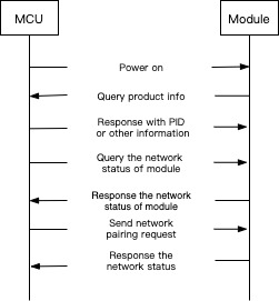
Involved UART communication protocol:
* 0x01: query the product information
* 0x02: query the network status of module
* 0x03: configure the Zigbee module
### Battery percentage status
You can show the battery percentage of the devices.
#### DP setting
| DP ID | Name | Description | Range of DP value |
| ----- | ------- | ---------------------------------------------------------------------------------------------------------------------------------------------------------------------------------------------------------------------------------------------------------------------------------------------------------------------------------------------------------------------------------------- | ----------------- |
| 10 | Battery | Show the current battery percentage of the device, unit: %.
The value is transmitted and updated in the following situations.
- The device is connected for the first time or reconnected.
- The device is restarted by replacing battery or other actions.
- The battery power changes.
- Periodically (for example, every 10 days) updated.
| 0\~100 |
Involved UART communication protocol: 0x05, status reporting in the real time
### Unlocking event record
The user can view the recorded unlocking history of the smart lock in the app.
However, you need to contact your account manager to use this function.
#### DP setting
| DP ID | Name | Description | Range of DP value |
| ----- | ----------------------- | ----------------------------------------------------- | ----------------- |
| 1 | Fingerprint recognition | The DP value can be used to distinguish the unlocker. | 0\~999 |
| 2 | Password | The DP value can be used to distinguish the unlocker. | 0\~999 |
| 3 | Temporary password | The DP value has no special meaning. | 0\~999 |
| 4 | Dynamic password | The DP value has no special meaning. | 0\~999 |
| 5 | Key card | The DP value can be used to distinguish the unlocker. | 0\~999 |
| 6 | Facial recognition | The DP value can be used to distinguish the unlocker. | 0\~999 |
| 7 | Door key | The DP value has no special meaning. | 0\~999 |
| 41 | App unlocking | The DP value has no special meaning. | 0\~999 |
| 44 | Iris recognition | The DP value can be used to distinguish the unlocker. | 0\~999 |
| 45 | Palm print recognition | The DP value can be used to distinguish the unlocker. | 0\~999 |
| 46 | Finger vein recognition | The DP value can be used to distinguish the unlocker. | 0\~999 |
* Fingerprint recognition, password, key card, facial recognition, iris recognition, palm print recognition, finger vein recognition: the DP value is valid from `0` to `999` and used to distinguish the unlocker. When transmitted, the control panel of the app displays the information of the corresponding unlocker. For example, if the transmitted DP value of a password unlocking event is `1`, and then *1 Password Unlocking* is displayed on the control panel. You can associate the unlocking event with app member to extent the displayed information, for more information, see the following section [Member management](https://docs.tuya.com/en/iot/smart-product-solution/product-solution-lock/product-solution-lock-zigbee/zigbee-doorlock-function-developer?id=K9fe9esofkzlf#Member-management).
* Temporary password, dynamic password, door key password, remote unlocking (app): the DP value is valid from `0` to `999` and has no special meaning. When transmitted, the control panel of the app only displays the information of the corresponding unlocking method. For example, if the transmitted DP value of a door key unlocking event is `25`, and then *Door Key Unlocking* is displayed on the control panel.
#### Process
When the door is successfully unlocked, the function name of the unlocking method is transmitted. To guarantee the consistency of the log with the actual unlocking event, Tuya Smart recommends that you use record type to transmit data, for more information, see the format of 0x23 command in the [Universal Docking Agreement](https://docs.tuya.com/en/iot/device-development/access-mode-product-solution/product-solution-lock/product-solution-lock-zigbee/zigbee-door-lock-universal-docking-agreement?id=K9bjcnh616mg5).
The module of a disconnected device stores the data that are failed to be transmitted, and re-transmits them together the next time, the time information of recorded data is determined by the local time of the device.
| Unlocking method | Function name | Range of DP value | Sample of DP value |
| ----------------------- | ------------------ | ------------------- | ------------------ |
| Fingerprint recognition | Fingerprint Unlock | Actual value | 1 |
| Password | Password | Actual value | 2 |
| Temporary password | Temporary Password | Any values are okay | 3 |
| Dynamic password | Dynamic Password | Any values are okay | 4 |
| Key card | Card | Actual value | 5 |
| Facial recognition | Face | Actual value | 6 |
| Door key | Key | Any values are okay | 7 |
| Remote unlocking (app) | App Unlock | Any values are okay | 8 |
| Iris recognition | Iris Unlock | Actual value | 9 |
| Palm print recognition | Palm Unlock | Actual value | 0 |
| Finger vein recognition | Finger Vein Unlock | Actual value | 999 |
See the following picture for the process.

Involved UART communication protocol: 0x23, data transmission in the record type
### Member management
App members comprise family members and visitor members.
* To become a family member, the user must have an app account and be invited by the device owner.
* A visitor member can be added without an app account. Visitor member is used to record the door lock and opening operation, and he or she cannot use the method of dynamic password, temporary password, and remote unlocking.
When adding members on the app, the user must assign them with unlocking methods. For example, the user adds the member *Tester* and assigns the *Fingerprint 3* to *Tester*. When the device transmits the door unlocking information of *Fingerprint 3*, the app displays *Tester, fingerprint recognized*. If the *Fingerprint 3* is not assigned to members, the app displays *3 Fingerprint Unlocking*.
#### Process

### Message and alarm
When the door lock alarm is triggered, the app can notify the alarm in time and the user can view the alarm record.
However, to use this function, you need to contact your Tuya account manager.
#### DP setting
| DP ID | Name | Description | Range of DP value |
| ----- | ------------ | ----------------------------------------------------------------------------------------------------------------------------------------------------------------------------------------------------------------------------------------------------------------------------------------------------------------------- | ------------------------------------------------------------------------------------------------------------------------------------------------------------------------------ |
| 9 | Alarm | An alarm can be declared when non-matching of fingerprints, passwords, key card, facial password, or door key happens, and when high temperature alarm, door opening timeout alarm, electronic latch not ejected, anti-pry alarm, the detection of door key, or low power alarm is triggered. | `wrong_finger`, `wrong_password`, `wrong_card`, `wrong_face`, `tongue_bad`, `too_hot`, `unclosed_time`, `tongue_not_out`, `pry`, `key_in`, `low_battery`, `power_off`, `shock` |
| 14 | Doorbell | It can be used when the door is equipped with the doorbell capacity. | {0,1} |
| 35 | Hijack Alarm | It can be used when the door is equipped with the hijack alarm capacity. A hijacking alarm is issued from the cloud rather than device. For example, if user sets the *Fingerprint 3* as the hijacking alarm trigger, the alarm will be triggered when the server side received the unlocking event of *Fingerprint 3*. | {0,1} |
#### Process
When the alarm is triggered, the MCU transmits the corresponding alarm DP value.
> **Note**: it is recommended to use the time of the local device when transmitting the data in the record type. If the device time lags behind the actual time, the alarm icon on the app does not flash when the alarm data is received, but the user can click and view the alarm record. However, if the timestamp of the alarm relies on the server time, the device will be connected to the Internet again after the network is disconnected, at this time, the app shows that the record time does not conform to the actual event.
See the following picture for the interaction process of an alarm.

See the following picture for the interaction process of a hijacking alarm.

Involved UART communication protocol: 0x23, data transmission in the record type
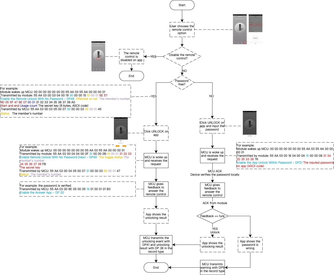
### Remote control on App
The user can remotely unlock the door with password and without password by using an App.
#### DP setting
| DP ID | Name | Description | Range of DP value |
| ----- | ------------------------------------ | ------------------------------------------------------------------------------------------------------------------------------------------------------------------------------------------------------------------------------------------------------------------------------------------------------------------------------------------------------------------------------------------------------------------------------------------------------------------- | --------------------------------------------------------- |
| 21 | App Unlock Within Password | A password is required when the door is remotely unlocked on app. The DP value is received by the MCU from the module. | The password that is configured by the user on the app |
| 22 | Answer App | It is used in cooperation with the remote door opening instruction including the *App Unlock Within Password*, *Set Key For Remote Unlock*, and *Remote Unlock With No Password (new)*. When the MCU receives remote control request from the app, the smart lock determines whether to open the door or not and transmits the DP value to the cloud. | {0,1} |
| 23 | Forbidden App Unlock | To disable the remote control function, the relevant feature must be pre-defined by the app. After disabling the remote control function, the user cannot unlock the door by using the app. | {0,1} |
| 41 | App Unlock | See the section Unlocking event record. | 0\~999 |
| 48 | Set Key For Remote Unlock | The user can disable or enable the secret key. If the user sets all accounts to be secret key free, the control panel calls HTTP interface to transmit *Set Key For Remote Unlock* of DP 48 to MCU. If the user chooses the **Forbidden App Unlock** or **App Unlock Within Password**, the control panel calls HTTP interface to transmit DP 48 to make the password free key invalid. The key is removed when the smart lock is restored to the factory settings. | The secret key that is created by the Tuya cloud platform |
| 49 | Remote Unlock With No Password (new) | The user does not need to enter password when unlocking the door on app. The DP value is received by the MCU from the module. | The secret key that is created by the Tuya cloud platform |
#### Process
The user sends a remote control from the app, and the smart lock verifies its validity after receiving the request, controls the locking status, and gives feedback to the control command.
### Dynamic password
The user generates a dynamic password on the app. Within the valid time (5 minutes), visitors can input the dynamic password on the smart lock to open the door.
#### Process
1. The dynamic password is created on the app.
2. The unlocker inputs a password on the smart lock.
3. The module of smart lock verifies the dynamic password.
4. The smart lock responds to the verification result by accepting or rejecting the unlocking request.
A dynamic password is a temporary password that is independent from the network. The authentication method of a dynamic password depends on the encrypted algorithm. When the smart lock receives a password suspected to be a dynamic password, the password, the current time, and the administrator password are transmitted to the Tuya module. The module performs the decryption of the received data in combination with the initial secret key saved by the module, and compares the password obtained after the decryption with the password entered by the user. If the two password is consistent, the module tells MCU to unlock the door. Otherwise, the unlocking operation is denied.

Involved UART communication protocol: 0x23, querying the dynamic password
### Temporary password
The user sets a temporary password on the app, within the valid period, visitors can input the temporary password on the smart lock to open the door.
#### DP setting
| DP ID | Name | Description |
| ----- | --------------------------- | -------------------------------------------------------------------------------------------------------------------------------------------------------------------------------------------------------------------------------------------------------------------------------------------------------------------------------------------------------------------------------------------------------------------------------------------------------------------- |
| 24 | Create Temporary Password | It is transmitted when the temporary password is created on app. |
| 25 | Delete Temporary Password | It is transmitted when the temporary password is deleted on app. |
| 26 | Update Temporary Password | It is transmitted when the password or validity period of the temporary password is modified on app. |
| 27 | Frozen Temporary Password | It is transmitted when the temporary password is frozen on app. A frozen temporary password can be resumed. |
| 28 | Unfreeze Temporary Password | It is transmitted when a frozen temporary password is resumed on app. |
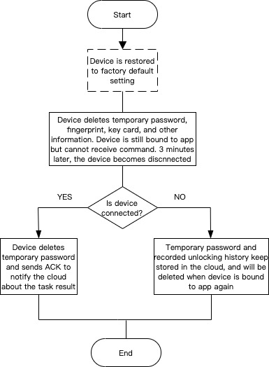
| 39 | Reset Temporary Password | It is used to restore the smart lock to factory setting and clear all temporary passwords. When the door lock is restored to the factory settings, the cloud makes a request to the smart lock to clear the local temporary password, after the restoration is completed, the cloud receives the temporary password status that are transmitted by the module. In case of network failure, the module transmits the result again when it is connected the next time. |
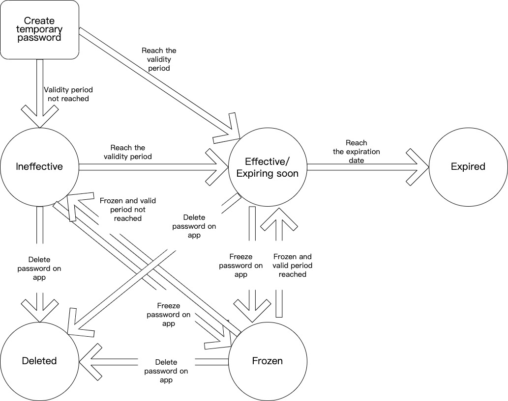
#### Status of temporary password
* Configuring: the temporary password is transmitted from the cloud to the device, but no feedback is given.
> **Note**: the module queries the temporary passwords that are in configuring status every hour or when the Zigbee gateway is connected. Once detected, the device updates the temporary password. However, the user can use app to proactively query the password (by calling APIs) when click the drop-down list of password.
* Ineffective: the temporary password does not reach the valid period.
* Effective: the temporary password is in use and there are more than 7 days from expiration.
* Expiring soon: the temporary password is in used and there are less than 7 days from expiration.
* Frozen: the temporary password is frozen on the app. If the password exceeds the validity period, the app cannot resume the password.
* Inactive: the password is expired.
* Deleted: the password is deleted on the app.
See the following picture for the relationship of the preceding status.
#### Process
A temporary password is only valid in a specific period. After the temporary password is created on the app, the cloud sends it to the smart lock, the password and the period of validity is stored in the smart lock. The temporary password is used within the valid period before the smart lock deletes or modifies it. The creation, deletion, and modification of the smart lock is dependent on the network availability.
The following picture illustrates how to create a temporary password.

### Factory setting restoration
Both the app and the smart lock can be restored to the factory default setting. This section takes the clearance and creation of temporary password as an example to describe the interaction process during the factory setting restoration.
#### Restore the app to factory setting
The following procedure describes the interaction process of the Tuya Smart App after restored to the factory default setting.
1. The user resets the app.
2. The cloud clears all the temporary password, recorded unlocking history, and other information.
3. The cloud sends the temporary password clearance command of DP 39 to smart lock.
* If the the DP 39 command is received, the smart lock clears the temporary password and returns an ACK to notify the cloud about the reception of DP 39.
* If the DP 39 command is not received due to network disconnection, the cloud proactively sends the command again when the network connection between the smart lock and the cloud resumes. And the smart lock clears the temporary password and returns an ACK to notify the cloud about the reception of DP 39.
Taking the creation of temporary password as an example, the following procedure describes the interaction process of the Tuya Smart App after the device is reset to the factory setting.
1. The smart lock is connected again after the restoration.
2. The user creates a temporary password on app.
3. The cloud checks the ACK confirmation from the device to determine if the devices has cleared the previous temporary password.
* If the device has cleared the temporary password and returned an ACK, the cloud allows the app to create temporary password.
* If the device does not clear the temporary password and return an ACK, the cloud transmits the DP 39 command to the device first, and waits for the ACK.
The following picture illustrates the process of the preceding description.

#### Restore the smart lock to factory setting
A smart lock must transmit the DP 39 to the cloud after factory setting restoration and temporary password clearance.
* If the cloud cannot receive the DP 39 because of network connection exception, the temporary password and unlocking history keep stored in the cloud, and the device must transmit the DP 39 again after the network connection is resumed.
* If the cloud receives the DP 39 successfully, the smart lock will be unbound with the app, the temporary password and unlocking history will be erased in the cloud. When the device is connected next time, the the temporary password and unlocking history in the app will be erased.
The following picture illustrates the process of the preceding description.