> For the complete documentation index, see [llms.txt](https://docs.ifreeq.com/llms.txt). Markdown versions of documentation pages are available by appending `.md` to page URLs; this page is available as [Markdown](https://docs.ifreeq.com/developer/smart-product-solution/gateway/mcu-access.md).
# MCU Access
## Tuya Gateway Development Overview
### Introduction
This article is mainly an overview of the MCU development process of Tuya Gateway general solution.
### Development Process
The development process mainly includes: product creation-hardware debugging-software development-functional debugging.
#### Create Product
Log in to the [IoT Workbench](https://iot.tuya.com/) and create a product. Select the product category according to the actual needs, and select Wi-Fi for the networking method. After the product is created, you can select the functions, panels, modules, and firmware according to the actual needs of the product and then download it to the MCU development kit.
The specific steps to create a product can refer to: [Product Creation-IoT Platform Operation](https://docs.tuya.com/en/iot/device-development/access-mode-mcu/mcu-access-guide/mcu-access-guide#IoT%20Platform%20Operation)

Sub-device creation: When creating a product, select a non-exempt development plan. If you can choose the protocol shown below, it is the sub-device plan.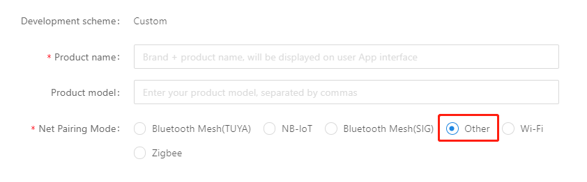
#### Hardware debugging
**Hardware selection**
When creating a product selection module, the platform will recommend some common module models. At present, the gateway MCU access solution can only be provided by Wi-Fi gateway module-WRG1.
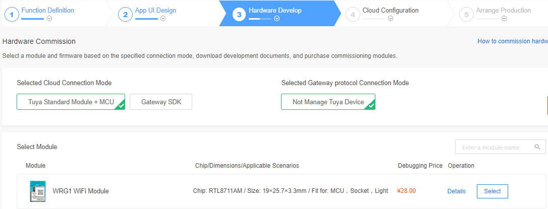
After selecting the module and firmware, you can purchase module samples online.
The hardware engineer can enter the drawing board stage, and the related materials for hardware development can be viewed in the document center:
Data manual link: [Wi-Fi Gateway Module-WRG1 Datasheet](https://docs.tuya.com/en/iot/device-development/module/wifi-module/wifiwrg1module)
Module minimum schematic: [Wi-Fi Gateway Module-WRG1 minimal system schematic diagram](https://docs.tuya.com/en/iot/smart-product-solution/product-solutiongateway/gateway-mcu-access-solution/tuya-gateway-development-overview?id=K9f3ph8kmsxsv) PCB data: [Common module package library](https://pan.baidu.com/s/10xJBTxyDQjweUI6C6LhrNQ)
**Distribution Network Verification**
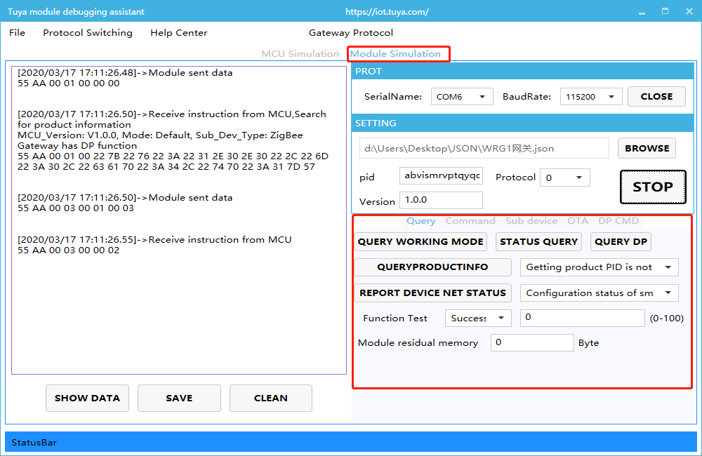
After getting the module, users do n’t need to worry about writing code first. It is recommended to use the module debugging assistant (MCU simulation mode) provided by Tuya to connect with the WRG1 module first. When verifying the module, users can be familiar with The protocol interaction process will greatly improve the efficiency of development and debugging later.

Tuya module debugging assistant-MCU simulation mode. The assistant will simulate the MCU to automatically reply the module's correct protocol data. After the module is networked with a mobile phone, the DP data can be reported and issued. The following briefly introduces the main steps of the assistant and module distribution network operation. Before using it, you need to know the instructions of Tuya Module Debugging Assistant in advance. Users who use the assistant for the first time can read in advance: [Module Debugging Assistant Instruction](https://docs.tuya.com/en/iot/device-development/access-mode-simmulator/access-mode-mdodule-simmulator)
**step1.** According to the minimum system schematic diagram, set up the module peripheral circuit, and simple test can directly fly the wire.
**step2.** Set device capabilities,open the Tuya module debugging assistant in the development kit and import the debugging file. Protocol selection Wi-Fi gateway protocol, MCU simulation mode.
**step3.** Connect the serial port of the module to the computer through the USB to TTL tool. The assistant selects the corresponding serial port and baud rate. Open the serial port and click Start. You will see that the module and the host computer automatically perform the initialization process protocol interaction.
**Note:** If no data is sent after power on, please check if the peripheral circuit of the module is correct.
**step4.** Click Reset Module, the module enters the network distribution mode. The module supports two modes of network configuration: EZ and AP mode ([the difference between EZ mode and AP mode](https://support.tuya.com/en/help/_detail/K9d1qfql1dekm)). The reset button will switch the network configuration mode. According to the status prompt, the App performs the corresponding network configuration operation. For the network configuration operation, you can read the instruction of the App. Attach a demo video of the network distribution in two modes: [Wi-Fi module network distribution demonstration video](https://www.bilibili.com/video/av44242203).

#### Software Development
In the process of hardware debugging, the user saw that the module and the MCU have a series of serial protocol protocol interaction data. For the understanding of these data, please refer to the protocol document in the development kit.
The agreement is mainly divided into two parts: the basic agreement and the functional agreement. The basic protocol has nothing to do with the product. It is a common protocol of the module, including module initialization instructions and some extended function instructions. The function protocol part is mainly based on the command word of the report of the basic protocol, and has explained the DP data content format in detail. The complete content of the basic protocol, the document center is kept updated in real time, you can click the link to view: [Tuya Cloud Gateway Access Protocol](https://docs.tuya.com/en/iot/smart-product-solution/product-solutiongateway/gateway-mcu-access-solution/tuya-gateway-development-overview?id=K9f3ph8kmsxsv)
There are two ways for MCU to interface with Tuya module: transplant the MCU SDK or connect the protocol by yourself.
* Self-docking agreement
When MCU resources are limited or the MCU SDK is not suitable for porting, customers can choose to connect the serial port protocol by themselves. The detailed explanation of serial port protocol can refer to: [Tuya Cloud Gateway Access Protocol Analysis](https://docs.tuya.com/en/iot/smart-product-solution/product-solutiongateway/gateway-mcu-access-solution/tuya-gateway-development-overview?id=K9f3ph8kmsxsv)
* Porting MCU SDK
If the MCU resources are sufficient, it is generally recommended that users directly port the MCU SDK for efficient and convenient development. The MCU SDK in the development kit is a C-based protocol application code provided by Tuya, which can be directly added to the MCU project. The MCU SDK requires MCU hardware resources: 4K bytes of Flash; RAM is related to the length of the DP point data, about 100 bytes (if OTA function is required, it must be greater than 260 bytes); the number of function nesting levels is 9 levels. If users with insufficient resources can connect the protocol by themselves, the functions in the SDK package can still be used as a reference.
MCU SDK porting tutorial, please refer to: [Tuya Wi-Fi Gateway MCU\_SDK Instructions](https://docs.tuya.com/zh/iot/device-development/access-mode-product-solution/product-solutiongateway/gateway-mcu-access-solution/tuya-gateway-mcu-sdk-demo-document)
#### Functional debugging
After porting the MCU SDK code development, you can use the Tuya module debugging assistant-module simulation mode to verify the correctness of the MCU code. The usage method is similar to the MCU simulation mode. In the simulation module mode, the assistant will automatically send the initialization data stream to verify that the MCU response is correct and give corresponding prompts for the incorrect data. After the initial interaction is passed, you can manually click to test other extended functions.
**Note:** Tuya module debugging assistant module simulation mode, without networking function, only used to verify the correctness of MCU serial protocol transmission and reception. After the test is completed, the MCU can be connected to the actual module and network.

Debugging common tool links:
[Background log query entry](https://docs.tuya.com/en/iot/guidelines-for-platform/operation-center/operation#Log%20query%3A%20Use%20Behavior%20Query%20on%20a%20Single-Device%20Basis): IoT Workbench-Operation Center. You can query related device background log data based on the device ID.
[Tuya Online Support Portal](https://docs.tuya.com/en/iot/guidelines-for-platform/support-center/troubleshooting): Tuya provides online support services. If the problem documents cannot be answered, you can Ask questions directly online, and the professional and technical team will answer your questions.
## Tuya Gateway MCU Access Communication Protocol
**Version Record:**
| Version | Revision description | Revised by | Revision date | Remarks |
| ------- | -------------------- | -------------- | ------------- | -------------------------------------------------------------------------------------------------------------------------------------------------------------------------------------------------------------------------------------------------------------------------------------------------------------------------------------------------------------------------------------------------------------------------------- |
| 1.0.0 | Document creation | Kang Liu | 20181018 | Document creation |
| 1.0.1 | Modify | Kang Liu | 20181025 | Modify version 3.3 sub-devices protocol added,add the time setting of heartbeat |
| 1.0.2 | Modify | Shanshan Zhou | 20181027 | 1.Add command to query product information
2.Add command to query MCU working mode
3.Report command of device network status
4.Add command of resetting WIFI
5.Add command of resetting WIFI-select configuration mode
6.Adjust the command code of each command
|
| 1.0.3 | Modify | Shanshan Zhou | 20181030 | 1.Delete the pid information in the product
2.Limit the port port in 3.2 to A-D
|
| 1.0.4 | Modify | Kang Liu | 20181107 | 1. Add sub-device operation of adding and deleting group under local group
2.Modify the query for product information,add device return ability (Whether local groups or local scenes is supported)
|
| 1.0.5 | Modify | Kang Liu | 20181107 | 1.Add return result set of group operation |
| 1.0.6 | Modify | Shanshan Zhou | 20190111 | 1.Add time to read (Green time and local time)
2.Add the function of adding sub-devices in bulk
3.Add the return result of adding sub-devices in bulk
4. sub\_id'0000'represent Gateway itself
5. Heartbeat interval time is at least 30S.
|
| 1.0.7 | Modify | Shanshan Zhou | 20190118 | 1.Add group control frame
2. Return 3.19 to the result of adding devices in bulk,change command word to 0x13.
3 Add group control command 0x014 4.Add production test command 0x15
|
| 1.0.8 | Modify | Shanshan Zhou | 20190319 | 1.The response after adding sub-devices. |
| 1.0.9 | Modify | Shanshan Zhou | 20190413 | 1.The bit3 adding cap identify internal sigmesh。
2.Add the frame of pulling network information
3.Add the frame of applying for network node
4.Add the frame of sigmesh sub-device
5.Add the frame which allows or disable to add sub-devices locally
6.Add the frame of getting module memory
|
| 1.1.0 | Modify | Shanshan Zhou | 20190520 | 1.The bit4 adding cap,if MCU ota function is available
2.Add remote service instruction
3.Add the frame of getting wifi status
4.Add the frame of deleting the sub-devices locally
5.Add the frame of querying sub-device list
6.Add the frame of restoring factory setting locally
7.Add the command of reporting removal status
8.Add the command of sig mesh getting the source node
|
| 1.1.1 | Modify | Shanshan Zhou | 20190529 | 1.Add group control command with sub\_id information
2.Add the command of getting dev\_key
3.The instruction of restoring the factory setting locally
4.Add the group control with sub\_id in product information
5.Add dev\_key when deleting the sub-devices of sigmesh gateway
|
| 1.1.2 | Modify | Shanshan Zhou | 20190713 | 1.Add serial port distribution network command (integrated)
2.Add serial transparent transmission network command (split)
3.Add the command of querying dp status
4.Add the command of clearing the sub-devices information by sigmesh
5.Add the command of sigmesh getting local ID
6.Add the command of sigmesh updating group address
7.The serial port upgrade subpacket is compatible with 128byte
|
| 1.1.3 | Modify | Shanshan Zhou | 20191202 | 1.Add tp code on product information
2.Add dual link extension protocol, add sub-device synchronization
3.Update sub-devices online / offline status
4.Add cancel heartbeat mechanism of the cap code added in product information
5.Add the command of getting Mac
6.Add record real-time reporting interface
7.Change heartbeat minimum interval from 30s to 60s
|
| 1.1.4 | Modify | Xiangjuan Meng | 20191212 | 1.Add tp code of product information
2. Change heartbeat interval from 60s to 180s
|
### Serial communication convention
Baud rate:115200
Data bit:8
Parity: None
Stop bit:1
Data flow control: none
MCU:User will control the chip through control board, connected with Tuya module through serial port
### Frame format description
| Field | Length(byte) | Description |
| ------------ | ------------ | -------------------------------------------------------------------------------------------- |
| Header | 2 | Fixed as 0x55aa |
| Version | 1 | Used for update and extension |
| Command word | 1 | Specific frame type |
| Data length | 2 | Large endian |
| Data | N | |
| Checksum | 1 | The result obtained by summing bytes from the beginning of the frame to the remainder of 256 |
### Basic agreement details
#### Query product information
Description:
1. product ID:Corresponding to the PID on Tuya IoT Platform, generated by Tuya IoT developer platform, used to record product related information in the cloud
2. The product information is comprised by product ID and MCU version
3. MCU version number format definition: in dotted decimal format,”x.x.x”(0<=x<=99),x is decimal.
Module send:
| Field | Length(byte) | Description |
| ------------ | ------------ | -------------------------------------------------------------------------------------------- |
| Header | 2 | 0x55aa |
| Version | 1 | 0x00/ 0x01
0x00:not supported to get pid;
0x01:supported to get pid;
|
| Command word | 1 | 0x01 |
| Data length | 2 | 0x0000 |
| Data | 0 | none |
| Checksum | 1 | The result obtained by summing bytes from the beginning of the frame to the remainder of 256 |
For example:0x55aa 00 01 0000 00
MCU return:
| Field | Length(byte) | Description |
| ------------ | ------------ | ------------------------------------------------------------------------------------------------------------------------------------------ |
| Header | 2 | 0x55aa |
| Version | 1 | 0x00/0x01 |
| Command word | 1 | 0x01 |
| Data length | 2 | N |
| Data | N | Version is 0x00:{“v”:”1.0.0”,”m”:1,”cap”:0, “tp”:4}
Version is 0x01: {“v”:”1.0.0”,”m”:1,”cap”:0, “tp”:4, “p”:”mhnmpqzf7ntzmmdb”}
|
| Checksum | 1 | The result obtained by summing bytes from the beginning of the frame to the remainder of 256 |
For example:{“v”:”1.0.0”,”m”:1,”cap”:0, “tp”:4,“p”:”mhnmpqzf7ntzmmdb”}
v means MCU version is 1.0.0
m represents pairing methods: 0 default pairing mode、1 Low power consumption mode、2 special pairing mode
cap represent device ability: bit0(local group),bit1(local scene) ,bit2(gateway have function dp), bit3(is sigmesh), bit4(support MCU upgrade), bit5(group control command with sub\_id) , bit6 (Bluetooth serial port paring mode,otherwise just AP mode is available)(the bit unused is 0)
Case 1: device support the local group control, cap is 1:
Case 2:device support local group control and local scene,cap is 3;
Case 3:device does not support local group control and local scene, but the gateway has function dp, cap is 4
Case 4:device is sigmesh device, with local group,it has to issue sub\_id when control the group(issue 0x22 command), cap is 41(0x29)
tp represents the sub-devices type integrated: 1:Zigbee 2:Bluetooth 3:Smart IR 4:Others if tp is not transmitted, it will be others defaultly; Pls note:The type of sub-devices: zigbee/Bluetooth/Smart IR are applied for Tuya self-developed products, if it the products developed by the customers, the sub-devices category will be others. p represent gateway product pid,pid is mhnmpqzf7ntzmmdb
#### Querying MCU, set the working mode of the module
Description:
1. The working mode of the module is mainly for how to indicate the working status of the Wi-Fi module and how to reset the Wi-Fi module. There are two main cases:
2. MCU cooperates with the module, that is, the module notifies the MCU through the serial port, the current working status is supported by the MCU, the Wi-Fi will be reset through the serial port when the MCU detect the reset request.
3. Module self-processing: The working status of the WIFI module drives the LED status display through the WIFI GPIO pin; WIFI reset is processed by detecting the GPIO input requirements
> The method of resetting the Wi-Fi module through module self-processing:WIFI will be triggered when detecting that the low level of GPIO entrance last for more than 5s. Reset: The GPIO pins used by the indicators and buttons are configured by the following commands.
Module send:
| Field | Length(byte) | Description |
| ------------ | ------------ | -------------------------------------------------------------------------------------------- |
| Header | 2 | 0x55aa |
| Version | 1 | 0x00 |
| Command word | 1 | 0x02 |
| Data length | 2 | 0x0000 |
| Data | 0 | none |
| Checksum | 1 | The result obtained by summing bytes from the beginning of the frame to the remainder of 256 |
For example:0x55aa 00 02 0000 01
MCU return:
| Field | Length(byte) | Description |
| ------------ | ------------ | ----------------------------------------------------------------------------------------------------------------------------------------------------------------------------------------------------------------------------------------------------------------- |
| Header | 2 | 0x55aa |
| Version | 1 | 0x00 |
| Command word | 1 | 0x02 |
| Data length | 2 | 0x0000/0x0004
0x0000:Indicating the module to work in the 'MCU and module co-processing' mode, the MCU needs to implement the functions mentioned in the "Description" above
0x0004:Instructing the module to work in "module self-processing" mode.
|
| Data | 0/2 | Data length is 4:
Data\[0]:WIFI indicator port,
Data\[1]: WIFI indicator pin,
Datat\[2]:reset button port,
Datat\[3]:reset button pin,
Port range:0-3 represent A-D
Pin range:0-7
|
| Checksum | 1 | The result obtained by summing bytes from the beginning of the frame to the remainder of 256 |
For example:0x55aa 00 02 0000 04(MCU work with the module)
0x55aa 00 02 0004 0103 0102 0C(module self-processing,indicator 0x0103:PB\_3,reset button 0x0102:PB\_2)
#### Report the device connection status
| Device connection status | Description | Status value |
| ------------------------ | -------------------------------------------------- | ------------ |
| Status 1 | smart configuration status | 0x00 |
| Status 2 | AP configuration status | 0x01 |
| Status 3 | WIFI is configured but not connected to the router | 0x02 |
| Status 4 | WIFI is configured and connected to the router | 0x03 |
| Status 5 | Connected to the router and the cloud | 0x04 |
| Status 6 | WIFI device is in low power mode | 0x05 |
Description:
1. Device connection status:1 smart configuration status 2 AP configuration status 3 WIFI is configured but not connected to the router 4 WIFI is configured and connected to the router 5 Device is connected to the router and the cloud. The LED indicator under 'module self-processing' working mode is:1 Flashing at intervals of 250ms;2 Flashing at intervals of 1500ms;3 Long dark status;4 or 5 Long light status
2. When the module detects that the MCU restarts or the MCU is disconnected and then goes online, it will sends the WIFI status to the MCU actively.
3. When the WIFI status of the module changes, it will actively send the WIFI status to the MCU
4. If the module working mode is set to 'module self-processing', the MCU does not need to implement this protocol
Module send:
| Field | Length(byte) | Description |
| ------------ | ------------ | ---------------------------------------------------------------------------------------------------------------------------- |
| Header | 2 | 0x55aa |
| Version | 1 | 0x00 |
| Command word | 1 | 0x03 |
| Data length | 2 | 0x0001 |
| Data | 1 | Indicating Wi-Fi working status:
0x00:Status 1
0x01:Status 2
0x02:Status 3
0x03:Status 4
0x04:Status 5
|
| Checksum | 1 | The result obtained by summing bytes from the beginning of the frame to the remainder of 256 |
For example:0x55aa 00 03 0001 00 03
MCU return:
| Field | Length(byte) | Description |
| ------------ | ------------ | -------------------------------------------------------------------------------------------- |
| Header | 2 | 0x55aa |
| Version | 1 | 0x00 |
| Command word | 1 | 0x03 |
| Data length | 2 | 0x0000 |
| Data | 0 | none |
| Checksum | 1 | The result obtained by summing bytes from the beginning of the frame to the remainder of 256 |
For example:0x55aa 00 03 0000 02
#### Reset WIFI
Description:
1. Resetting WIFI status transition as shown below: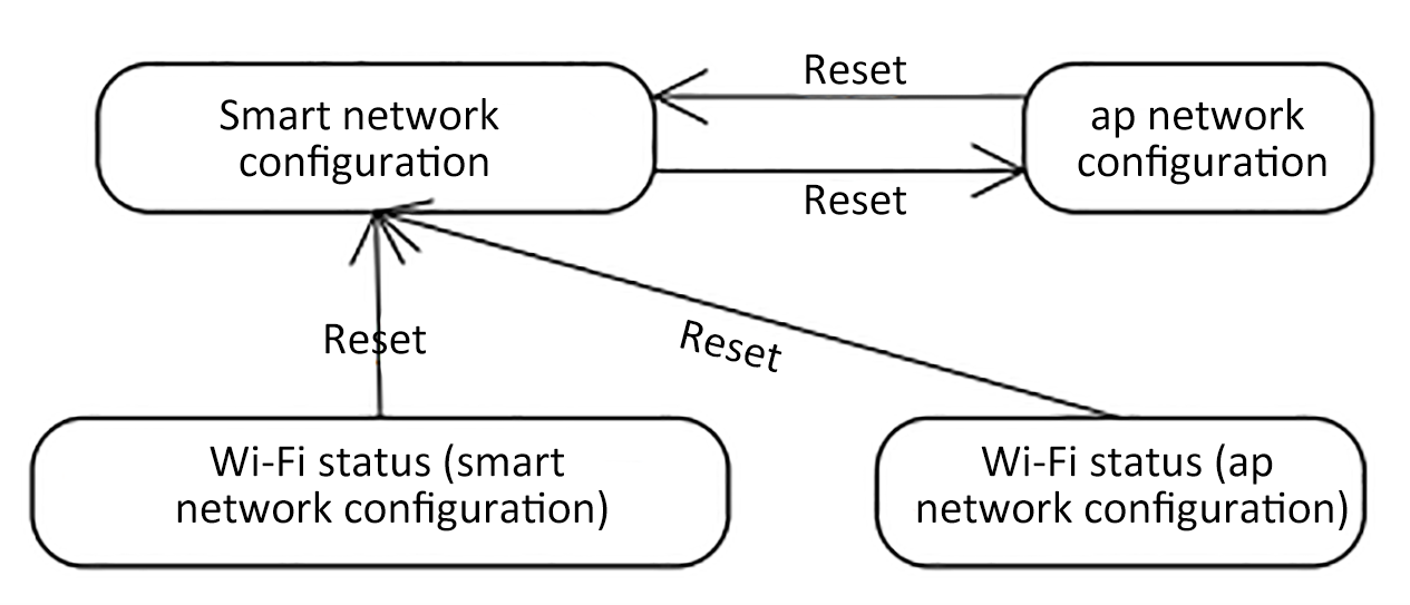The self-processing WIFI reset method of the module is: Wi-Fi will be triggered for reset when detecting the low level of the GPIO entrance for more than 5s.
2. If the module working mode is set to 'module self-processing', the MCU does not need to implement this protocol
MCU send:
| Field | Length(byte) | Description |
| ------------ | ------------ | -------------------------------------------------------------------------------------------- |
| Header | 2 | 0x55aa |
| Version | 1 | 0x00 |
| Command word | 1 | 0x04 |
| Data length | 2 | 0x0000 |
| Data | 0 | none |
| Checksum | 1 | The result obtained by summing bytes from the beginning of the frame to the remainder of 256 |
For example:0x55aa 00 04 0000 03
Module return:
| Field | Length(byte) | Description |
| ------------ | ------------ | -------------------------------------------------------------------------------------------- |
| Header | 2 | 0x55aa |
| Version | 1 | 0x00 |
| Command word | 1 | 0x04 |
| Data length | 2 | 0x0000 |
| Data | 0 | none |
| Checksum | 1 | The result obtained by summing bytes from the beginning of the frame to the remainder of 256 |
For example:0x55aa 00 04 0000 03
#### Reset WIFI-select the configuration mode
Description:
1. Compared with 'Reset WIFI' in section 3.5, this section provides the MCU to selectively choose the configuration method after resetting the WIFI depend on different conditions.
2. MCU solution users can selectively implement this protocol depend on their requirements.
3. If the module working mode is set to 'module self-processing', the MCU does not need to implement this protocol
MCU send:
| Field | Length(byte) | Description |
| ------------ | ------------ | -------------------------------------------------------------------------------------------- |
| Header | 2 | 0x55aa |
| Version | 1 | 0x00 |
| Command word | 1 | 0x05 |
| Data length | 2 | 0x0001 |
| Data | 1 | 0x00:get into smart configuration mode
0x01:get into AP configuration mode
|
| Checksum | 1 | The result obtained by summing bytes from the beginning of the frame to the remainder of 256 |
For example:0x55aa 00 05 0001 00 05,get into smart configuration mode
Module return:
| Field | Length(byte) | Description |
| ------------ | ------------ | -------------------------------------------------------------------------------------------- |
| Header | 2 | 0x55aa |
| Version | 1 | 0x00 |
| Command word | 1 | 0x05 |
| Data length | 2 | 0x0000 |
| Data | 0 | none |
| Checksum | 1 | The result obtained by summing bytes from the beginning of the frame to the remainder of 256 |
Foe example:0x55aa 00 05 0000 04
#### Allow sub-device to access the network
Description:
1. The App sends a network access permission to the Gateway, and allows the sub-device to access the network within a certain period of time.
Module send:
| Field | Length(byte) | Description |
| ------------ | ------------ | -------------------------------------------------------------------------------------------- |
| Header | 2 | 0x55aa |
| Version | 1 | 0x00 |
| Command word | 1 | 0x06 |
| Data length | 2 | 0x0000 |
| Data | 0 | none |
| Checksum | 1 | The result obtained by summing bytes from the beginning of the frame to the remainder of 256 |
MCU return:
| Field | Length(byte) | Description |
| ------------ | ------------ | -------------------------------------------------------------------------------------------- |
| Header | 2 | 0x55aa |
| Version | 1 | 0x00 |
| Command word | 1 | 0x06 |
| Data length | 2 | 0x0000 |
| Data | 0 | none |
| Checksum | 1 | The result obtained by summing bytes from the beginning of the frame to the remainder of 256 |
#### Disable the permission of sub-device accessing the network
Description:
The App sends a command to close the network to the Gateway
Module send:
| Field | Length(byte) | Description |
| ------------ | ------------ | -------------------------------------------------------------------------------------------- |
| Header | 2 | 0x55aa |
| Version | 1 | 0x00 |
| Command word | 1 | 0x07 |
| Data length | 2 | 0x0000 |
| Data | 0 | None |
| Checksum | 1 | The result obtained by summing bytes from the beginning of the frame to the remainder of 256 |
MCU return:
| Field | Length(byte) | Description |
| ------------ | ------------ | -------------------------------------------------------------------------------------------- |
| Header | 2 | 0x55aa |
| Version | 1 | 0x00 |
| Command word | 1 | 0x07 |
| Data length | 2 | 0x0000 |
| Data | 0 | None |
| Checksum | 1 | The result obtained by summing bytes from the beginning of the frame to the remainder of 256 |
#### Add sub-device
Description:
1. MCU send the sub-device network access to Wi-Fi
2. pk\_type is alternate field, can be ignored, the default value is 1
MCU send:
| Field | Length(byte) | Description |
| ------------ | ---------------------------------------------------------------- | --------------------------------------------------------------------------------------------------------------------------------------------------------------------------------------------------------------------------------------------------------------------------------------------------------------------------------------------------------------------------------------------------------- |
| Header | 2 | 0x55aa |
| Version | 1 | 0x00 |
| Command word | 1 | 0x08 |
| Data length | 2 | N |
| Data | { 'pk\_type':xx, 'sub\_id':'xxxx', 'pid':'xxxx', 'ver':'x.x.x' } | User product classification pk\_type: The user-defined product type is optional to be filled
Sub-device identification sub\_id: Generally it is MAC address or chip id, it has to be Uniqueness. '0000' is not allowed.'0000' represent the gateway itself.
Product identification pid: Product ID(ProductID),when creating the product generated by the Tuya cloud
version:such as 1.0.0
|
| Checksum | 1 | The result obtained by summing bytes from the beginning of the frame to the remainder of 256 |
Module return:
| Field | Length(byte) | Description |
| ------------ | ------------ | ------------------------------------------------------------------------------------------------------------------------------------- |
| Header | 2 | 0x55aa |
| Version | 1 | 0x00 |
| Command word | 1 | 0x08 |
| Data length | 2 | 0x0001 |
| Data | 1 | 0x00 accept the request
0x01 refuse the request (Whether the sub-device is connected to the network successfully, see 3.19)
|
| Checksum | 1 | The result obtained by summing bytes from the beginning of the frame to the remainder of 256 |
#### Delete the sub-device
Description:
The App sends a command to close the network to the Gateway.
Module send:
| Field | Length(byte) | Description |
| ------------ | ------------------------------------ | -------------------------------------------------------------------------------------------- |
| Header | 2 | 0x55aa |
| Version | 1 | 0x00 |
| Command word | 1 | 0x09 |
| Data Length | 2 | N |
| Data | { “sub\_id”:”xxxx”, “devkey”:”xxx” } | the sub-device id to be deleted Devkey: used to remove sigmesh sub-device |
| Checksum | 1 | The result obtained by summing bytes from the beginning of the frame to the remainder of 256 |
MCU return:
| Field | Length(byte) | Description |
| ------------ | ------------ | -------------------------------------------------------------------------------------------- |
| Header | 2 | 0x55aa |
| Version | 1 | 0x00 |
| Command word | 1 | 0x09 |
| Data length | 2 | 0x0000 |
| Data | 0 | None |
| Checksum | 1 | The result obtained by summing bytes from the beginning of the frame to the remainder of 256 |
#### Heartbeat detection
Description:
WIFI module schedule(1-3 mins)detect the online/offline status of sub-device. When adding sub-devices in batches,heartbeat detection will stop.
Module send:
| Field | Length(byte) | Description |
| ------------ | -------------------- | -------------------------------------------------------------------------------------------- |
| Header | 2 | 0x55aa |
| Version | 1 | 0x00 |
| Command word | 1 | 0x0A |
| Data length | 2 | N |
| Data | { “sub\_id”:“xxxx” } | sub\_id:sub-device ID |
| Checksum | 1 | The result obtained by summing bytes from the beginning of the frame to the remainder of 256 |
MCU return:
\| Field | Length(byte) | Description |
\| -------- | --------------------------------- | ------------------------------------------------------------ | | Header | 2 | 0x55aa | | Version | 1 | 0x00 | | Command word | 1 | 0x0A | | Data length | 2 | N | | Data | { “sub\_id”:“xxxx”, “hb\_time”:xx } | sub\_id:sub-device ID\
Heartbeat intervalhb\_time(Unit: second)for example:60 means 60 seconds,0 does not support heartbeat,always online。If the heartbeat interval is less than 180s, it will be processed for 180s (except 0) | | Checksum | 1 | The result obtained by summing bytes from the beginning of the frame to the remainder of 256 |
Description:
The online device needs to responde to the heartbeat. If it does not reply for two consecutive heartbeat cycles, the device is considered offline.
#### Status query
Description:
Used to synchronize the status of sub-devices.
Module send:
| Field | Length(byte) | Description |
| ------------ | ------------ | -------------------------------------------------------------------------------------------- |
| Header | 2 | 0x55aa |
| Version | 1 | 0x00 |
| Command word | 1 | 0x0B |
| Data length | 2 | N |
| Data | 0 | None |
| Checksum | 1 | The result obtained by summing bytes from the beginning of the frame to the remainder of 256 |
MCU return:(3.13 status report)
#### Command issue
Description:
Control command issue.
datapoint: command status unit:
1. datapoint: the command / status data unit is as follows:
| Data segment | length(byte) | Description | | | |
| ------------ | ------------ | -------------------------------------------------------------------------------------------------------------------------------- | -------------------- | -------------- | --------------------------------------------------------------- |
| dpid | 1 | datapoint Serial number | | | |
| type | 1 | corresponding to the specific data type of a datapoint on IoT platform, it is identified by the following 'representation value' | | | |
| | | type | Representation value | length (bytes) | description |
| | | raw | 0x00 | N | corresponding to raw datapoint(Module transparent transmission) |
| | | bool | 0x01 | 1 | value range:0x00/0x01 |
| | | value | 0x02 | 4 | corresponding to int type,large endian representation |
| | | string | 0x03 | N | corresponding to a specific string |
| | | enum | 0x04 | 1 | Enum,range from 0-255 |
| | | bitmap | 0x05 | 1/2/4 | when the length is more than 1 byte,using large endian |
| len | 2 | number of bytes corresponding to length (big endian) | | | |
| value | 1/2/4/N | hex represent,big endian transmission for larger than 1 byte | | | |
1. datapoint command/ except for the 'raw' type, other types of state data units belong to the 'obj' type datapoint
2. 'command issue' contains several datapoint 'command data unit'
3. 'command issue' is asynchronous processing protocol,corresponding to MCU datapoint 'status report'
Module send:
| Field | Length(byte) | Description |
| ------------ | ------------------------------------------ | ------------------------------------------------------------------------------------------------------------------------------------------------------------------------------------------------------------ |
| Header | 2 | 0x55aa |
| Version | 1 | 0x00 |
| Command word | 1 | 0x0C |
| Data length | 2 | N |
| Data | id\_len(1byte) + sub\_id(nbyte)+ datapoint | id\_len: sub-device id length
sub\_id: sub-device id, when sub\_id is '0000',means that this command is to the gateway itself's dp (main device). datapoint: Control command data point collection
|
| Checksum | 1 | The result obtained by summing bytes from the beginning of the frame to the remainder of 256 |
#### Status report
Description:
The sub-device actively pushes the instruction after the command is issued and replied or the status changes.
MCU send:
\| Field | Length(byte) | Description |
\| -------- | ---------------------------------------- | ------------------------------------------------------------ | | Header | 2 | 0x55aa | | Version | 1 | 0x00 | | Command word | 1 | 0x0D | | Data length | 2 | N | | Data | id\_len(1byte) + sub\_id(nbyte)+ datapoint | id\_len: sub-device id length\
sub\_id: sub-device id. when the sub\_id is '0000',this command is to the gateway itself's dp (main device) . datapoint: Control command data point collection | | Checksum | 1 | The result obtained by summing bytes from the beginning of the frame to the remainder of 256 |
#### Group sub-device join in
Description:Local group sub-devices are added, support local group-created devices. Module send:
| Field | Length(byte) | Description |
| ------------ | ---------------------------------------- | --------------------------------------------------------------------------------------------------------------------------------------- |
| Header | 2 | 0x55aa |
| Version | 1 | 0x00 |
| Command word | 1 | 0x0E |
| Data length | 2 | N |
| Data | { “gid”:”01”, “cids”:\[”12”,”34”,”56”] } | gid represents group id cids:The set of sub-devices to join the group. For example:sub-device ”12”,”34”,”56” will join in to group ”01” |
| Checksum | 1 | The result obtained by summing bytes from the beginning of the frame to the remainder of 256 |
MCU return:
| Field | Length(byte) | Description |
| ------------ | --------------------------------------------------------- | ---------------------------------------------------------------------------------------------------------------------------------------------------------------------------------------------------------------------------------------------------- |
| Header | 2 | 0x55aa |
| Version | 1 | 0x00 |
| Command word | 1 | 0x0E |
| Data length | 2 | N |
| Data | { “gid”:”12”, “cids”:\[”12”,”34”,”56”], “rets”:\[0,0,0] } | gid represents group id cids:The collection of sub-devices to join the group,the return result combined with rets: 0:add successfully 1:group limit exceeded 2:sub-device times out 3:the value exceed the limit 4:file writing error 5:other errors |
| Checksum | 1 | The result obtained by summing bytes from the beginning of the frame to the remainder of 256 |
#### Group sub-device deletion
Description:The local group sub-device is deleted.
Module send:
| Field | Length(byte) | Description |
| ------------ | ------------------------------ | ---------------------------------------------------------------------------------------------------------------------------------------- |
| Header | 2 | 0x55aa |
| Version | 1 | 0x00 |
| Command word | 1 | 0x0F |
| Data length | 2 | N |
| Data | { 'gid':'01', 'cids':\['12'] } | gid represents group id cids:The collection of sub-devices to be deleted. For example:Sub-device '12' need to be deleted from group '01' |
| Checksum | 1 | The result obtained by summing bytes from the beginning of the frame to the remainder of 256 |
MCU return:
| Field | Length(byte) | Description |
| ------------ | ------------------------------------------- | ------------------------------------------------------------------------------------------------------------------------------------------------------------------------------------------------------------------------------------------------------------------------------------ |
| Header | 2 | 0x55aa |
| Version | 1 | 0x00 |
| Command word | 1 | 0x0F |
| Data length | 2 | N |
| Data | { “gid”:”01”, “cids”:\[”12”], “rets”:\[0] } | gid represents group id
cids:The collection of sub-devices to join the group
the return results combined with rets:
0:add successfully
1:group limit exceeded
2:sub-device times out
3:the value exceed the limit
4:file writing error
5:other errors
|
| Checksum | 1 | The result obtained by summing bytes from the beginning of the frame to the remainder of 256 |
#### Get system time (Green Time)
MCU send:
| Field | Length(byte) | Description |
| ------------ | ------------ | -------------------------------------------------------------------------------------------- |
| Header | 2 | 0x55aa |
| Version | 1 | 0x00 |
| Command word | 1 | 0x10 |
| Data length | 2 | 0x0000 |
| Data | 0 | None |
| Checksum | 1 | The result obtained by summing bytes from the beginning of the frame to the remainder of 256 |
For example:0x55aa 00 10 0000 0F
Module return:
| Field | Length(byte) | Description |
| ------------ | ------------ | -------------------------------------------------------------------------------------------------------------------------------------------------------------------------------------------------------------------------------------------------------------------------------------------------------------------------------------------------------------------------------------------------------------------- |
| Header | 2 | 0x55aa |
| Version | 1 | 0x00 |
| Command word | 1 | 0x10 |
| Data length | 2 | 0x0007 |
| Data | 7 | data length is 7 bytes: Data\[0] is the symbol whether to obtain the time successfully, 0 means failure, 1 means success Data \[1] is the year, 0x00 means 2000 Data\[2] means month,start from Jan, end with Dec Data\[3] means data,start from 1st, end with 31st.Data\[4] means hours,start from 0, end with 23 Data\[5] means mins,start from 0, end with 59. Data\[6] means seconds ,start from 0, end with 59. |
| Checksum | 1 | The result obtained by summing bytes from the beginning of the frame to the remainder of 256 |
For example:0x55aa 00 10 0007 01 10 04 13 05 06 07 50(April 19, 2016 5: 6: 7 GMT)
#### Obtain system time
MCU send:
| Field | Length(byte) | Description |
| ------------ | ------------ | -------------------------------------------------------------------------------------------- |
| Header | 2 | 0x55aa |
| Version | 1 | 0x00 |
| Command word | 1 | 0x11 |
| Data length | 2 | 0x0000 |
| Data | xxxx | None |
| Checksum | 1 | The result obtained by summing bytes from the beginning of the frame to the remainder of 256 |
Module return:
| Field | Length(byte) | Description |
| ------------ | ------------ | ----------------------------------------------------------------------------------------------------------------------------------------------------------------------------------------------------------------------------------------------------------------------------------------------------------------------------------------------------------------------------------------------------------------------------------------------------------------------------- |
| Header | 2 | 0x55aa |
| Version | 1 | 0x00 |
| Command word | 1 | 0x11 |
| Data length | 2 | 0x0008 |
| Data | Data | data length is 8 bytes: Data\[0]is the symbol whether to obtain the time successfully, 0 means failure, 1 means success Data \[1] is the year, 0x00 means 2000 Data\[2] means month,start from Jan, end with Dec Data\[3] means data,start from 1st, end with 31st.Data\[4] means hours,start from 0, end with 23 Data\[5] means mins,start from 0, end with 59. Data\[6] means seconds ,start from 0, end with 15. Data\[7] means week,start from 1, end with 7. 1 means Mon |
| Checksum | 1 | The result obtained by summing bytes from the beginning of the frame to the remainder of 256 |
For example:
(1)If the device is activated in China, the local time is Beijing time (East 8 District)
0x55aa 00 11 0008 01 10 04 13 05 06 07 02 54(Beijing time April 19, 2016 5: 6: 7)
(2)If the device is activated abroad, the local time is the time zone of the device
#### Add devices in bulk
Description:Add multiple sub-devices of the same pid in batch. Note:The maximum number of sub-devices added in a batch is 32. MCU send:
| Field | Length(byte) | Description |
| ------------ | ---------------------------------------------------------- | -------------------------------------------------------------------------------------------------------------------------------------------------------------------- |
| Header | 2 | 0x55aa |
| Version | 1 | 0x00 |
| Command word | 1 | 0x12 |
| Data length | 2 | N |
| Data | { “pid”:” xxxx”, “cids”:\[”12”,”34”,”56”], “ver”:”x.x.x” } | product identity pid: Product ID(ProductID),generated by the Tuya cloud when creating the product cids:Collection of sub-devices to be added. ver: for example:1.0.0 |
| Checksum | 1 | The result obtained by summing bytes from the beginning of the frame to the remainder of 256 |
Module return:
| Field | Length(byte) | Description |
| ------------ | ------------ | --------------------------------------------------------------------------------------------------- |
| Header | 2 | 0x55aa |
| Version | 1 | 0x00 |
| Command word | 1 | 0x12 |
| Data length | 2 | N |
| Data | 1 | 00 indicates that accept the data successfully, data 01 means that accept or parsing unsuccessfully |
| Checksum | 1 | The result obtained by summing bytes from the beginning of the frame to the remainder of 256 |
#### Back to add device result
Description:inform the MCU result when adding the devices successfully
Module send:
| Field | Length(byte) | Description |
| ------------ | --------------------------------------------- | ---------------------------------------------------------------------------------------------------- |
| Header | 2 | 0x55aa |
| Version | 1 | 0x00 |
| Command word | 1 | 0x13 |
| Data length | 2 | N |
| Data | { “cids”:\[”12”,”34”,”56”], “rets”:\[0,0,0] } | cids:the collection of sub-devices, the returned results combined with rets: 0:success non-0:failure |
| Checksum | 1 | The result obtained by summing bytes from the beginning of the frame to the remainder of 256 |
MCU return:
| Field | Length(byte) | Description |
| ------------ | ------------ | -------------------------------------------------------------------------------------------- |
| Header | 2 | 0x55aa |
| Version | 1 | 0x00 |
| Command word | 1 | 0x13 |
| Data length | 2 | 0000 |
| Data | None | |
| Checksum | 1 | The result obtained by summing bytes from the beginning of the frame to the remainder of 256 |
#### Control group command issu
Module send:
| Field | Length(byte) | Description |
| ------------ | ------------------------------------------ | -------------------------------------------------------------------------------------------------- |
| Header | 2 | 0x55aa |
| Version | 1 | 0x00 |
| Command word | 1 | 0x14 |
| Data length | 2 | N |
| Data | id\_len(1byte) + grp\_id(nbyte)+ datapoint | id\_len: group id length grp\_id: group id datapoint: the collection of control command data point |
| Checksum | 1 | The result obtained by summing bytes from the beginning of the frame to the remainder of 256 |
MCU return:
| Field | Length(byte) | Description |
| ------------ | ------------ | -------------------------------------------------------------------------------------------- |
| Header | 2 | 0x55aa |
| Version | 1 | 0x00 |
| Command word | 1 | 0x14 |
| Data length | 2 | 0000 |
| Data | none | |
| Checksum | 1 | The result obtained by summing bytes from the beginning of the frame to the remainder of 256 |
#### WIFI functionality test
Description:scan the specific SSID: tuya\_mdev\_test, return the scanning result and signal percentage
MCU send:
| Field | Length(byte) | Description |
| ------------ | ------------ | -------------------------------------------------------------------------------------------- |
| Header | 2 | 0x55aa |
| Version | 1 | 0x00 |
| Command word | 1 | 0x15 |
| Data length | 2 | 0x0000 |
| Data | Data | None |
| Checksum | 1 | The result obtained by summing bytes from the beginning of the frame to the remainder of 256 |
Module return:
| Field | Length(byte) | Description |
| ------------ | ------------ | ----------------------------------------------------------------------------------------------------------------------------------------------------------------------------------------------------------------------------------------------------------------------------------------------------------------------------------------------------------------------------- |
| Header | 2 | 0x55aa |
| Version | 1 | 0x00 |
| Command word | 1 | 0x15 |
| Data length | 2 | 0x0002 |
| Data | 2 | data length is 2 bytes; Data\[0]: 0x00 failure, 0x01 success; when Data\[0] is 0x01,means success,Data\[1] represent signal strength (0-100, 0 has the worst signal,100 has the best signal). When Data\[0] is 0x00,means failure, Data\[1] 0x00 represent scan the specific ssid unsuccessfully,Data\[1] is 0x01 means that the module was not written the authorization key |
| Checksum | 1 | The result obtained by summing bytes from the beginning of the frame to the remainder of 256 |
#### Obtain the WIFI status
Description:The MCU can obtain the WIFI status according to this command. See 3.3 for specific WIFI status. The gateway will not restore the wifi state before the network initialization is completed.
MCU send:
| Field | Length(byte) | Description |
| ------------ | ------------ | -------------------------------------------------------------------------------------------- |
| Header | 2 | 0x55aa |
| Version | 1 | 0x00 |
| Command word | 1 | 0x16 |
| Data length | 2 | 0x0000 |
| Data | Data | None |
| Checksum | 1 | The result obtained by summing bytes from the beginning of the frame to the remainder of 256 |
Module return:
| Field | Length(byte) | Description |
| ------------ | ------------ | -------------------------------------------------------------------------------------------- |
| Header | 2 | 0x55aa |
| Version | 1 | 0x00 |
| Command word | 1 | 0x16 |
| Data length | 2 | 0x0001 |
| Data | 1 | Wi-Fi working status: 0x00:status 1 0x01:status 2 0x02:status 3 0x03:status 4 0x04:status 5 |
| Checksum | 1 | The result obtained by summing bytes from the beginning of the frame to the remainder of 256 |
#### Restore to the factory setting(optional)
Description:The local factory restoration will cause the cloud information and local information to be out of sync, and it must be used while the device is online or before the device is activated for the first time.
MCU send:
| Field | Length(byte) | Description |
| ------------ | ------------ | -------------------------------------------------------------------------------------------- |
| Header | 2 | 0x55aa |
| Version | 1 | 0x00 |
| Command word | 1 | 0x17 |
| Data length | 2 | 0x0000 |
| Data | 0 | None |
| Checksum | 1 | The result obtained by summing bytes from the beginning of the frame to the remainder of 256 |
#### Report the removing status
Description:1)When the gateway receive the command of remove or restore the factory setting, it will report to the MCU.
2)If only receive the removing instruction, the gateway will only remove the distribution network and will not delete the sub-device information. The sub-device information will still be displayed on the App the next time the device is online.
3)If receiving the factory restoring instruction, the gateway will remove the network distribution and delete all sub-devices information.
Module send:
| Field | Length(byte) | Description |
| ------------ | ------------ | --------------------------------------------------------------------------------------------------------------------------- |
| Header | 2 | 0x55aa |
| Version | 1 | 0x00 |
| Command word | 1 | 0x18 |
| Data length | 2 | 0x0001 |
| Data | 1 | 0x00 restore the factory setting locally 0x01 remove remotely 0x02 remove locally 0x03 restore the factory setting remotely |
| Checksum | 1 | The result obtained by summing bytes from the beginning of the frame to the remainder of 256 |
#### 3.25 delete the sub-devices locally
Description:
MCU send the command to delete the sub-devices
MCU send:
| Field | Length(byte) | Description |
| ------------ | ------------------- | -------------------------------------------------------------------------------------------- |
| Header | 2 | 0x55aa |
| Version | 1 | 0x00 |
| Command word | 1 | 0x19 |
| Data length | 2 | N |
| Data | { “sub\_id”:”xxx” } | |
| Checksum | 1 | The result obtained by summing bytes from the beginning of the frame to the remainder of 256 |
Module return:
| Field | Length(byte) | Description |
| ------------ | ------------ | -------------------------------------------------------------------------------------------- |
| Header | 2 | 0x55aa |
| Version | 1 | 0x00 |
| Command word | 1 | 0x19 |
| Data length | 2 | 0x0001 |
| Data | 1 | 0x00 delete successfully 0x01 delete unsuccessfully |
| Checksum | 1 | The result obtained by summing bytes from the beginning of the frame to the remainder of 256 |
#### Allow to stop adding sub-devices locally
MCU send:
| Field | Length(byte) | Description |
| ------------ | ------------ | ----------------------------------------------------------------------------------------------------------------------------------------------------------------------- |
| Header | 2 | 0x55aa |
| Version | 1 | 0x00 |
| Command word | 1 | 0x1A |
| Data length | 2 | 0x0003 |
| Data | 3 | Data\[0]: 0:close the entrance to add the sub-devices 1:allow to add sub-devices data\[1]: allow to add the time(high bytes) data\[2]: allow to add the time(low bytes) |
| Checksum | 1 | The result obtained by summing bytes from the beginning of the frame to the remainder of 256 |
Module return:
| Field | Length(byte) | Description |
| ------------ | ------------ | -------------------------------------------------------------------------------------------- |
| Header | 2 | 0x55aa |
| Version | 1 | 0x00 |
| Command word | 1 | 0x1A |
| Data length | 2 | 0x0001 |
| Data | 1 | 0:success 1:failure |
| Checksum | 1 | The result obtained by summing bytes from the beginning of the frame to the remainder of 256 |
#### Obtain the module memory
Description:obtain the remaining memory of Wi-Fi module
MCU send:
| Field | Length(byte) | Description |
| ------------ | ------------ | -------------------------------------------------------------------------------------------- |
| Header | 2 | 0x55aa |
| Version | 1 | 0x03 |
| Command word | 1 | 0x1B |
| Data length | 2 | 0x0000 |
| Data | Data | none |
| Checksum | 1 | The result obtained by summing bytes from the beginning of the frame to the remainder of 256 |
Module return:
| Field | Length(byte) | Description |
| ------------ | ------------ | -------------------------------------------------------------------------------------------- |
| Header | 2 | 0x55aa |
| Version | 1 | 0x00 |
| Command word | 1 | 0x1B |
| Data length | 2 | 0x0004 |
| Data | 4 | data length is 4 bytes, large endian: 0x00 0x00 0x28 0x00 represent 10240 remaining memory |
| Checksum | 1 | The result obtained by summing bytes from the beginning of the frame to the remainder of 256 |
#### Query the sub-device list
Description: 1)MCU can query all sub-devices list under the gateway.
2)when the list data is larger than 255 bytes, it will be sent separately MCU send:
| Field | Length(byte) | Description |
| ------------ | ------------ | -------------------------------------------------------------------------------------------- |
| Header | 2 | 0x55aa |
| Version | 1 | 0x00 |
| Command word | 1 | 0x1C |
| Data length | 2 | 0x0000 |
| Data | 0 | None |
| Checksum | 1 | The result obtained by summing bytes from the beginning of the frame to the remainder of 256 |
Module return:
| Field | Length(byte) | Description |
| ------------ | --------------------------------------------------------------------------------- | ----------------------------------------------------------------------------------------------------------------------------------------------------------------------------------------------------------------------------------------------------------------------------------------- |
| Header | 2 | 0x55aa |
| Version | 1 | 0x00 |
| Command word | 1 | 0x1C |
| Data length | 2 | N |
| Data | id(1byte)+sub\_num(1byte) sub1\_len(1byte)+sub1\_id+….. subn\_len(1byte)+subn\_id | id: bit 7: FALSE all sub-devices address have been sent TRUE there will still have sub-device address and a package of data. Bit0-6: package number start from 0. sub\_num: the number of sub-devices of this package of data. sub1\_len: sub-device id length sub1\_id: sub-device id …. |
| Checksum | 1 | The result obtained by summing bytes from the beginning of the frame to the remainder of 256 |
#### OTA service
Description:
1. When to upgrade the firmware will depend on the configurations customers set on IoT platform, module will only serves as a data transmission channel that supports MCU upgrades, and does not do any analysis of the data content.
2. Currently, the MCU OTA supports 4 methods on IoT Platform as follows.
3. App reminder upgrade:the end user will receive the pop-up message of upgrade every time they enter the device panel, the end user will decide update or not.
4. App silent upgrade:there is no pop-up reminder of this method, The firmware will automatically detect the upgrade within one minute after it is powered on. If the upgrade package is found and with a higher version, it will automatically start to pull the relevant upgrade package. After the first power-on, the module will go to the cloud to detect whether there is an upgrade package configuration every 24 hours.
5. App forced upgrade: the end user will receive the pop-up message of this method, the panel cannot be used normally if the end user does not confirm the upgrade.
6. App detection upgrade: there is not pop-up message on the app side, the end user has to click 'check the firmware upgrade' to detect if newer version is available. The pop-up message only appears when newer version is available.
7. MCU OTA process:
After the Wi-Fi module has sent all the upgrade packages, re-send the 01 command word (3.2 query product information). The MCU needs to reply within one minute to the software version number in the product information with the upgraded MCU version number. The version number needs to be the same as the upgraded version number configured at the Tuya backend.
**MCU start upgrade**
Description:
After the Wi-Fi module has sent all the upgrade packages, re-send the 01 command word (3.1 query product information). The MCU needs to reply within one minute with the software version number in the product information with the upgraded MCU version number. The version number needs to be the same as the upgraded version number configured at Tuya backend.

Module send:
| Field | Length(byte) | Description |
| ------------ | ------------------ | -------------------------------------------------------------------------------------------- |
| Header | 2 | 0x55aa |
| Version | 1 | 0x00 |
| Command word | 1 | 0x1D |
| Data length | 2 | 0x0004 |
| Data | file\_size (4byte) | file\_size: the upgrade file size,unsigned int,the large endian |
| Checksum | 1 | The result obtained by summing bytes from the beginning of the frame to the remainder of 256 |
MCU return:
| Field | Length(byte) | Description |
| ------------ | ------------ | ----------------------------------------------------------------------------------------------------------------------------------------------- |
| Header | 2 | 0x55aa |
| Version | 1 | 0x00 |
| Command word | 1 | 0x1D |
| Data length | 2 | 0x0001 |
| Data | 1 | the sub-packet transmission size of upgrade package: 0x00:default 256byte(Compatible with old firmware) 0x01:512byte 0x02:1024byte 0x03:128byte |
| Checksum | 1 | The result obtained by summing bytes from the beginning of the frame to the remainder of 256 |
**MCU OTA package transmission**
Description:
1. Upgrade package transmission data format: the package offset (unsigned short) + package data
2. The package transmission will be end when the MCU receive the data length is 4 and the package offset is >= the size of firmware
Module send:
| Field | Length(byte) | Description |
| ------------ | -------------------------------- | -------------------------------------------------------------------------------------------- |
| Header | 2 | 0x55aa |
| Version | 1 | 0x00 |
| Command word | 1 | 0x1E |
| Data length | 2 | 0x0004+m |
| Data | offset\_addr(4byte)+ pack(mbyte) | offset\_addr: the package offset pack: Packet content |
| Checksum | 1 | The result obtained by summing bytes from the beginning of the frame to the remainder of 256 |
For example:
If the size of upgraded package is 530 Bytes,(The last package data response is optional)
(1) The first package data,the package offset is 0x00000000,the length is 256
0x55aa 00 1e 0104 00000000 xx…xx XX
(2) The second package data,the package offset is 0x00000100,the length is 256
0x55aa 00 1e 0104 00000100 xx…xx XX
(3) The third package data,the package offset is 0x00000200,the length is 18
0x55aa 00 1e 0016 00000200 xx…xx XX
(4) The last package,the package offset is 0x00000212,the length is 0
0x55aa 00 1e 0004 00000212 xx...xx XX
MCU return:
| Field | Length(byte) | Description |
| ------------ | ------------ | -------------------------------------------------------------------------------------------- |
| Header | 2 | 0x55aa |
| Version | 1 | 0x00 |
| Command word | 1 | 0x1E |
| Data length | 2 | 0x0000 |
| Data | 0 | None |
| Checksum | 1 | The result obtained by summing bytes from the beginning of the frame to the remainder of 256 |
**The sub-device upgrade start**
Module send:
| Field | Length(byte) | Description |
| ------------ | -------------------------------------------------- | ------------------------------------------------------------------------------------------------------------------------- |
| Header | 2 | 0x55aa |
| Version | 1 | 0x00 |
| Command word | 1 | 0x1F |
| Data length | 2 | N |
| Data | id\_len(1byte) + sub\_id(nbyte)+ file\_size(4byte) | id\_len: su-device id length sub\_id: sub-device id file\_size: the size of upgrade package,unsigned int,the large endian |
| Checksum | 1 | The result obtained by summing bytes from the beginning of the frame to the remainder of 256 |
MCU return:
| Field | Length(byte) | Description |
| ------------ | ------------ | ----------------------------------------------------------------------------------------------------------------------------------------------- |
| Header | 2 | 0x55aa |
| Version | 1 | 0x00 |
| Command word | 1 | 0x1F |
| Data length | 2 | 0x0001 |
| Data | 1 | the sub-packet transmission size of upgrade package: 0x00:default 256byte(Compatible with old firmware) 0x01:512byte 0x02:1024byte 0x03:128byte |
| Checksum | 1 | The result obtained by summing bytes from the beginning of the frame to the remainder of 256 |
**Sub device upgrade package transmission**
Description:
1. Upgrade package transmission data format: package offset (unsigned short) + package data
2. The package transmission will be end when the MCU receive the data length is 4 and the package offset is >= the size of firmware
Module send:
| Field | Length(byte) | Description |
| ------------ | ----------------------------------------------------------------- | -------------------------------------------------------------------------------------------------------- |
| Header | 2 | 0x55aa |
| Version | 1 | 0x00 |
| Command word | 1 | 0x20 |
| Data length | 2 | N |
| Data | id\_len(1byte) + sub\_id(nbyte)+ offset\_addr(4byte)+ pack(mbyte) | id\_len: sub-device id length sub\_id: sub-device id offset\_addr: the offset address pack: data package |
| Checksum | 1 | The result obtained by summing bytes from the beginning of the frame to the remainder of 256 |
For example:
If sub\_id 为”1234”, the size of upgrade package is 530 Bytes,(The last package data response is optional)
(1) The first package data,the package offset is 0x00000000,the data length is 256
0x55aa 00 20 0109 04 31 32 33 34 00000000 xx…xx XX
(2) The second package data,the package offset is 0x00000100,the data length is 256
0x55aa 00 20 0109 04 31 32 33 34 00000100 xx…xx XX
(3) The third package data,the package offset is 0x00000200,the data length is 18
0x55aa 00 20 001B 04 31 32 33 34 00000200 xx…xx XX
(4) The third package data,the package offset is 0x00000212,the data length is 0
0x55aa 00 20 0009 04 31 32 33 34 00000212 xx...xx XX
MCU return:
| Field | Length(byte) | Description |
| ------------ | ------------ | -------------------------------------------------------------------------------------------- |
| Header | 2 | 0x55aa |
| Version | 1 | 0x00 |
| Command word | 1 | 0x20 |
| Data length | 2 | 0x0000 |
| Data | 0 | none |
| Checksum | 1 | The result obtained by summing bytes from the beginning of the frame to the remainder of 256 |
**Query sub-device version number**
Module send:
| Field | Length(byte) | Description |
| ------------ | ------------------- | -------------------------------------------------------------------------------------------- |
| Header | 2 | 0x55aa |
| Version | 1 | 0x00 |
| Command word | 1 | 0x21 |
| Data length | 2 | N |
| Data | { “sub\_id”:”xxx” } | sub\_id:sub-device id |
| Checksum | 1 | The result obtained by summing bytes from the beginning of the frame to the remainder of 256 |
MCU return:
| Field | Length(byte) | Description |
| ------------ | ------------------------------------ | -------------------------------------------------------------------------------------------- |
| Header | 2 | 0x55aa |
| Version | 1 | 0x00 |
| Command word | 1 | 0x21 |
| Data length | 2 | N |
| Data | { | sub\_id: sub-device ID ver: sub-device firmware version |
| | “sub\_id”:”xxx”, “ver”:”xx.xx.xx”, } | |
| Checksum | 1 | The result obtained by summing bytes from the beginning of the frame to the remainder of 256 |
#### the group control command issue (with sub\_id)
Module send:
| Field | Length(byte) | Description |
| ------------ | ----------------------------------------------------------------------------- | ------------------------------------------------------------------------------------------------------------------------------------------------------------------------ |
| Header | 2 | 0x55aa |
| Version | 1 | 0x00 |
| Command word | 1 | 0x22 |
| Data length | 2 | N |
| Data | grp\_len(1byte) + grp\_id(nbyte)+ sub\_len(1byte) + sub\_id(mbyte)+ datapoint | grp\_len: group id length grp\_id: group id sub\_len: sub-device (one sub-device in the group)id length sub\_id sub-device id datapoint: control command data collection |
| Checksum | 1 | The result obtained by summing bytes from the beginning of the frame to the remainder of 256 |
MCU return:
| Field | Length(byte) | Description |
| ------------ | ------------ | -------------------------------------------------------------------------------------------- |
| Header | 2 | 0x55aa |
| Version | 1 | 0x00 |
| Command word | 1 | 0x22 |
| Data length | 2 | 0000 |
| Data | none | |
| Checksum | 1 | The result obtained by summing bytes from the beginning of the frame to the remainder of 256 |
#### serial port distribution network (Integrated)
MCU send:
| Field | Length(byte) | Description |
| ----------- | ----------------------------------- | -------------------------------------------------------------------------------------------- |
| Header | 2 | 0x55aa |
| Version | 1 | 0x00 |
| Command | 1 | 0x23 |
| Data length | 2 | N |
| Data | { “s”:”xxx”, ”p”:”yyy”, ”t”:”zzz” } | s:ssid p:password t:token,由App生成 |
| Checksum | 1 | The result obtained by summing bytes from the beginning of the frame to the remainder of 256 |
Module return:
| Field | Length(byte) | Description |
| ------------ | ------------ | -------------------------------------------------------------------------------------------- |
| Header | 2 | 0x55aa |
| Version | 1 | 0x00 |
| Command word | 1 | 0x23 |
| Data length | 2 | 0x0001 |
| Data | none | 0x00:success 0x01:not in pairing status 0x02: json data illegal |
| Checksum | 1 | The result obtained by summing bytes from the beginning of the frame to the remainder of 256 |
#### Serial port transparent transmission distribution network (distributed)
**WiFI send the broadcast**
Description:The data packet is transparently transmitted by the Wi-Fi module to the MCU module for broadcasting
Module send:
| Field | Length(byte) | Description |
| ------------ | ------------ | -------------------------------------------------------------------------------------------- |
| Header | 2 | 0x55aa |
| Version | 1 | 0x00 |
| Command word | 1 | 0x24 |
| Data length | 2 | N |
| Data | N | broadcast package |
| Checksum | 1 | The result obtained by summing bytes from the beginning of the frame to the remainder of 256 |
MCU return:
| Field | Length(byte) | Description |
| ------------ | ------------ | -------------------------------------------------------------------------------------------- |
| Header | 2 | 0x55aa |
| Version | 1 | 0x00 |
| Command word | 1 | 0x24 |
| Data length | 2 | 0x0002 |
| Data | 2 | status return: data\[0]: 0x00:success 0x01:fail data\[1]: success: 0 fail: failure reason |
| Checksum | 1 | The result obtained by summing bytes from the beginning of the frame to the remainder of 256 |
**MCU send the network pairing information**
Description:The data packet is transparently transmitted by the App to the WI-Fi through the MCU
MCU send:
| Field | Length(byte) | Description |
| ------------ | ------------ | -------------------------------------------------------------------------------------------- |
| Header | 2 | 0x55aa |
| Version | 1 | 0x00 |
| Command word | 1 | 0x25 |
| Data length | 2 | N |
| Data | data | Encrypted data |
| Checksum | 1 | The result obtained by summing bytes from the beginning of the frame to the remainder of 256 |
Module return:
| Field | Length(byte) | Description |
| ------------ | ------------ | -------------------------------------------------------------------------------------------- |
| Header | 2 | 0x55aa |
| Version | 1 | 0x00 |
| Command word | 1 | 0x25 |
| Data length | 2 | 0x0000 |
| Data | none | |
| Checksum | 1 | The result obtained by summing bytes from the beginning of the frame to the remainder of 256 |
**WIFI report the network paring information**
Description:Data package will be transmitted transparently to the app from the MCU through Wi-Fi
Module send:
| Field | Length(byte) | Description |
| ------------ | ------------ | -------------------------------------------------------------------------------------------- |
| Header | 2 | 0x55aa |
| Version | 1 | 0x00 |
| Command word | 1 | 0x26 |
| Data length | 2 | N |
| Data | data | Encrypted data |
| Checksum | 1 | The result obtained by summing bytes from the beginning of the frame to the remainder of 256 |
MCU return:
| Field | Length(byte) | Description |
| ------------ | ------------ | -------------------------------------------------------------------------------------------- |
| Header | 2 | 0x55aa |
| Version | 1 | 0x00 |
| Command word | 1 | 0x26 |
| Data length | 2 | 0x0000 |
| Data | none | |
| Checksum | 1 | The result obtained by summing bytes from the beginning of the frame to the remainder of 256 |
**MCU connection status**
Description:The MCU will actively push the connection status with the mobile to the wifi module.
MCU send:
| Field | Length(byte) | Description |
| ------------ | ------------- | -------------------------------------------------------------------------------------------- |
| Header | 2 | 0x55aa |
| Version | 1 | 0x00 |
| Command word | 1 | 0x27 |
| Data length | 2 | 0x0001 |
| Data | Connect state | connection status: 0x00 disconnected 0x01 connected |
| Checksum | 1 | The result obtained by summing bytes from the beginning of the frame to the remainder of 256 |
**Wi-Fi module disconnect actively**
Module send:
| Field | Length(byte) | Description |
| ------------ | ------------ | -------------------------------------------------------------------------------------------- |
| Header | 2 | 0x55aa |
| Version | 1 | 0x00 |
| Command word | 1 | 0x28 |
| Data length | 2 | 0x0000 |
| Data | none | |
| Checksum | 1 | The result obtained by summing bytes from the beginning of the frame to the remainder of 256 |
MCU return:
| Field | Length(byte) | Description |
| ------------ | ------------ | -------------------------------------------------------------------------------------------- |
| Header | 2 | 0x55aa |
| Version | 1 | 0x00 |
| Command word | 1 | 0x28 |
| Data length | 2 | 0x0000 |
| Data | none | |
| Checksum | 1 | The result obtained by summing bytes from the beginning of the frame to the remainder of 256 |
#### Query dp status
Module send:
| Field | Length(byte) | Description |
| ------------ | --------------------------------------- | -------------------------------------------------------------------------------------------- |
| Header | 2 | 0x55aa |
| Version | 1 | 0x00 |
| Command word | 1 | 0x29 |
| Data length | 2 | N |
| Data | { “sub\_id”:”xxx”, “dpid”:\[xx,xx,xx] } | sub\_id: device id: dpid: corresponding dpid group |
| Checksum | 1 | The result obtained by summing bytes from the beginning of the frame to the remainder of 256 |
MCU return:3.13 protocol(command word 0x0D)
#### Update the status of sub-device online/offline
MCU send:
| Field | Length(byte) | Description |
| ------------ | --------------------------------------------------------------------------- | --------------------------------------------------------------------------------------------------------------------------------------------------------------------------------------------------- |
| Header | 2 | 0x55aa |
| Version | 1 | 0x00 |
| Command word | 1 | 0x2A |
| Data length | 2 | N |
| Data | {"all":0,"cids":\["xxx","xxx"],"state":1} or
{"all":1,""state":1}
| all:
0 represent not all sub-devices,only cids data;
1:represent all sub-devices,cis is unnecessary to be transferred。
cids:device id group。
state:
0:offline ;
1:online 。
|
| Checksum | 1 | The result obtained by summing bytes from the beginning of the frame to the remainder of 256 |
Module return:
| Field | Length(byte) | Description |
| ------------ | ------------ | -------------------------------------------------------------------------------------------- |
| Header | 2 | 0x55aa |
| Version | 1 | 0x00 |
| Command word | 1 | 0x2A |
| Data length | 2 | 0x0001 |
| Data | 1 | 0x00:success
0x01:failure
|
| Checksum | 1 | The result obtained by summing bytes from the beginning of the frame to the remainder of 256 |
**get module MAC address**
MCU send:
| Field | Length(byte) | Description |
| ------------ | ------------ | -------------------------------------------------------------------------------------------- |
| Header | 2 | 0x55aa |
| Version | 1 | 0x00 |
| Command word | 1 | 0x2B |
| Data length | 2 | 0x0000 |
| Data | 0 | |
| Checksum | 1 | The result obtained by summing bytes from the beginning of the frame to the remainder of 256 |
Module return:
| Field | Length(byte) | Description |
| ------------ | ------------ | -------------------------------------------------------------------------------------------------------------------------------------------------------------------------------------------------------------------------------------------------------------------------------- |
| Header | 2 | 0x55aa |
| Version | 1 | 0x00 |
| Command word | 1 | 0x2B |
| Data length | 2 | 0x0007 |
| Data | data | data\[0]:
the success or failure symbol of getting MAC address :
0x00 represent success and the MAC address with 6 bytes is valid;
0x01 means failed to obtain MAC address,and the MAC address with 6 bytes is invalid
data\[1]\~data\[6]: module MAC address
|
| Checksum | 1 | The result obtained by summing bytes from the beginning of the frame to the remainder of 256 |
**Recorded status report in real time (with time)**
Description:\
1)For record-type sub-devices such as door locks, the dp status is also reported with the time stamp when these records were generated\
2)This reporting interface is a synchronous reporting interface. After the mcu report data, you can check the result returned from the module to determine the success of the report.
Module send:
| Field | Length(byte) | Description |
| ------------ | --------------------------------------- | ------------------------------------------------------------------------------------------------------------------------------------------------------------------------------------------------------------------------------------------------------------------------------------------------------------------------------------------------------------------------------------------------------------------------------------------------------------------------------------------------------------------------------------------------------------------------------------------------------------------------------------------------------------------------------------------------------------------------------------------------------------------------------------------------------------------------------------------------------------------------------------------------------------------------------------- |
| Header | 2 | 0x55aa |
| Version | 1 | 0x00 |
| Command word | 1 | 0x2C |
| Data length | 2 | N |
| Data | time | Data length is 7 bytes:
data \[0] indicates whether this data transmission has a time flag:
0 means that this data does not have the time after the time, the module task data is invalid and not processed;
1 indicates that the following time data is valid, and the local time (date format) where the time data is reported.
2 indicates that the following time data is valid, and the Green Time (date format) where the time data is reported.
3 indicates that the following time data is valid, the time data is time stamped, and the accuracy is up to s.
date format:
data\[1] is year,0x00 means year 2000
data\[2] is month,start from 1 to 12
data\[3] is date,from 1 to 31
data\[4] is hour,from 0-23
data\[5] is minute,from 0-59
data\[6] is second,from 0-59
timestamp:
data\[1]\~data\[4] is 4 bytes timestamp, large endian.
data\[5]\~data\[6] fill with 0
|
| | id\_len(1byte)+sub\_id(nbyte)+datapoint |
id\_len:
sub-device id length;
sub\_id:
sub-device id, when sub\_id is '0000',means that the gateway itself's dp will be reported
datapoint:
Status command data point collection
|
| Checksum | 1 | The result obtained by summing bytes from the beginning of the frame to the remainder of 256 |
MCU return:
| Field | Length(byte) | Description |
| ------------ | ------------ | -------------------------------------------------------------------------------------------- |
| Header | 2 | 0x55aa |
| Version | 1 | 0x00 |
| Command word | 1 | 0x2C |
| Data length | 2 | 0x0001 |
| Data | | 0:success 1:failure |
| Checksum | 1 | The result obtained by summing bytes from the beginning of the frame to the remainder of 256 |
## FAQs
### Version Record
| Version | Revision description | Revised by | Revision date | Remarks |
| ------- | -------------------- | -------------- | ------------- | ------- |
| 1.0.0 | Document creation | Chunsheng Zhao | 20200325 | |
### Q:How many sub-devices can be connected under one gateway?
A:1:Up to 128 sub-devices; 2:The number of sub-devices added at one time cannot exceed 32
### Q:Does it support 433, Bluetooth and 485 sub-devices?
A:Gateway general MCU integration:MCU is developed by customers according to the Wi-Fi module Tuya provides. As long as the MCU sends data according to the serial port protocol, it can access the Tuya platform. Therefore, the general connection of the gateway is not related to the communication type of the sub-device.
### Q:What is the number of local linkages?
A:This is related to the number of conditions and actions created by the user. One condition is about 250 bytes, and one action is about 200 bytes. If you create 1 condition and 5 actions, it is not recommended to exceed 10.
### Q:How to set sub-device heartbeat interval by the MCU?
A:The MCU sets the next heartbeat interval in the heartbeat reply frame. The default heartbeat interval time is 1min, and the minimum settable heartbeat interval is 180s
### Q:When will the module query the sub-device heartbeat?
A:The module will query the sub-device heartbeat before the heartbeat cycle arrives, and the heartbeat of the sub-device will be delivered in advance (8S + random seconds). This is to avoid the condition that the MCU has no time to deal with the heartbeat when multiple sub-devices sending the heartbeat at the same time.
### Q:How does the module determine the online or offline status of the sub-device?
A:The module will send a heartbeat query package to the MCU in ahead of time before the heartbeat cycle arrives. If the MCU does not reply within 8s, the heartbeat query package will be retransmitted again. If the MCU has not responded in 3 times. The module will report to the cloud that device is offline. After that, the module will stop sending a heartbeat frame until the MCU sends a status frame of the sub-device to the WiFi module. The module will notify the cloud to be online and restart the sub-device heartbeat.
### Q:When will the module refresh the heartbeat and re-start?
A:During the heartbeat interval, the module will refresh the heartbeat and re-start when it receives the status data of the sub-device.
### Q:What is the maximum frame and frequency that the module serial port can receive?
A:It is recommend that each frame of the data does not exceed 256 bytes, if the amount of data needed to synchronise the status of the sub-device after networking is quite a few, it can be sent in packets. The frame interval is recommended to be 100ms.
### Q:'pid', 'sub\_id', 'gid‘,any length limitation of these fields?
A:'pid' can be filled in created on IoT platform. The length of 'sub\_id' cannot exceed 25 bytes. 'gid' is decided when the module issue,the range is from 0 to 65535,the length cannot exceed 5 bytes.
### Q:Any limitation of MCU or sub-device version number?
A:yes,the firmware version number format is xx.xx.xx x is from 0 to 9
### Q:Will the sub-device information still exist when the gateway is removed?
A:The information of sub-devices will be kept if only removing the gateway. However, the sub-device information will not be available when the gateway is restored to the factory setting. Besides, the information also be invalid when the device is re-paired under another app account.
### Q:After the serial port command is issued, how long does it take for the MCU not to reply with an ACK?
A: The default timeout time for general commands is 500ms. Heartbeat detection is 8s.
### Q:What if the App issues a control command but the sub-device is not detected offline in time?
A:The commando will be resent, resent 2 times in 1s interval -> resent 3 times at 10s intervals -> stop resending
### Q:How to control WiFi module hardware reset?
A:Pull low the pin 8-EN
### Q:How to obtain the Wi-Fi running log?
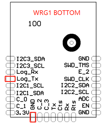
A:When you encounter problems during debugging and need to obtain the module operation log for Tuya analysis, as shown above, the flying line leads the `Log_Tx` and`GND` pins, connect the USB to serial port tool, the serial port configuration `38400,8, N, 1`, Use the PC serial assistant to grab the log to save the text, and give it to the graffiti engineer for analysis.
### If the above methods cannot solve my issues?
Pls log in Tuya IoT Platform,[Tuya online support team](https://docs.tuya.com/zh/iot/guidelines-for-platform/support-center/troubleshooting), Tuya will have professional engineers to answer your questions online. In order to quickly understand and solve your problem, it is recommended that you describe your problem in the following format:
-Problem background: For example,I am the engineer of XYZ company, doing XX solution for now. -Problem description: Describe as far as possible the conditions under which your problem occurs. What is the problem phenomenon? Can it be re-appeared? -Problem attachments: Please upload attachments for screenshots or logs of faulty scenes if you have.
---
# Agent Instructions
This documentation is published with GitBook. GitBook is the documentation platform designed so that both humans and AI agents can read, navigate, and reason over technical content effectively. Learn more at gitbook.com.
## Querying This Documentation
If you need additional information that is not directly available in this page, you can query the documentation dynamically by asking a question.
Perform an HTTP GET request on the current page URL with the `ask` query parameter, and the optional `goal` query parameter:
```
GET https://docs.ifreeq.com/developer/smart-product-solution/gateway/mcu-access.md?ask=&goal=
```
`ask` is the immediate question: it should be specific, self-contained, and written in natural language.
`goal` is optional and describes the broader end goal you are ultimately trying to accomplish on behalf of the user. GitBook uses it to tailor the answer towards what is most useful for that goal.
The response will contain a direct answer to the question and relevant excerpts and sources from the documentation.
Use this mechanism when the answer is not explicitly present in the current page, you need clarification or additional context, or you want to retrieve related documentation sections.