> For the complete documentation index, see [llms.txt](https://docs.ifreeq.com/llms.txt). Markdown versions of documentation pages are available by appending `.md` to page URLs; this page is available as [Markdown](https://docs.ifreeq.com/developer/device-development/access-mode-soc/electrician/guidance.md).
# Guidance
## Creating a Development-free Electrical Engineering Product on the Tuya Smart Platform
### Registering with and Logging In to the Tuya Smart Platform
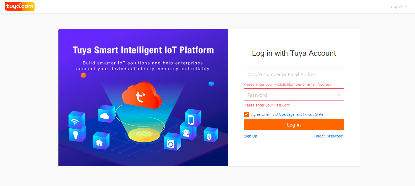
1. Register with and log in to the Tuya Smart platform at .
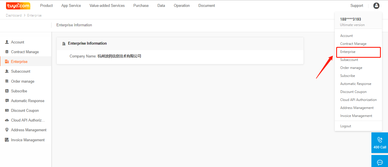
2. (Recommended) Complete enterprise certification to upgrade your account to a corporate account with more functions.
### Creating a Development-free Smart Electrical Engineering Product
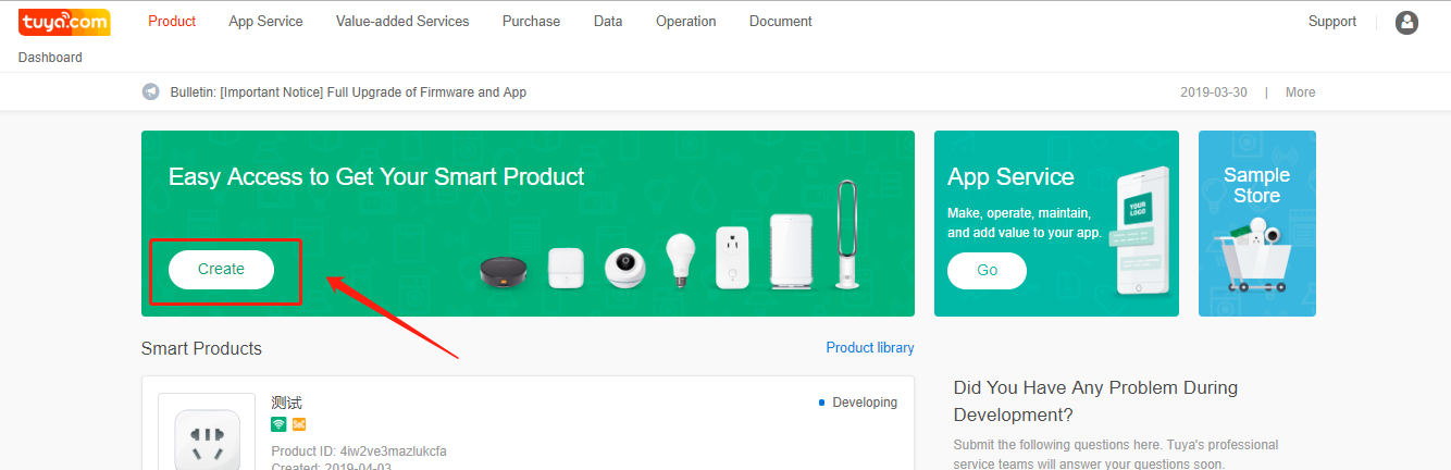
1. On the **Product** page, click **Create** in the **Easy Access to Get Your Smart Product** area.
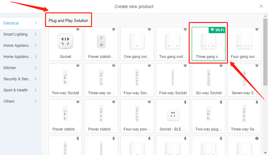
2. On the displayed **Create new product** page, choose **Electrical** and select a socket or switch under **Plug and Play Solution**. Alternatively, select a product under **Custom** if the development-free solution cannot meet your product function requirements.


1. Specify the product name, which will be displayed on the App control panel.
2. Specify the internal or customer product model to facilitate product maintenance and order management.
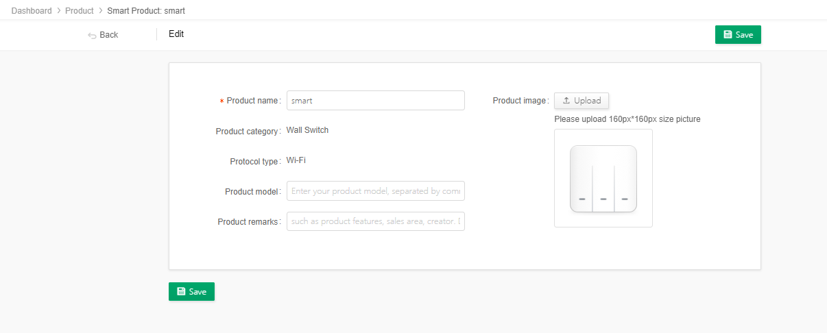
3. After the product is created, click **Edit Product Information** on the product configuration page to modify the product name and model.
4. If you subscribe to a third-party service for the product, the third-party service subscription icon is highlighted for the product on the **Product** page.


### Configuring the App Control Panel
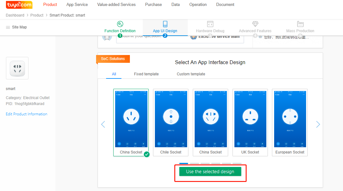
1. Click **App UI Design**. If you have upgraded your account to a corporate account, more templates and panel UI functions are available.
2. Select a control panel template and use the Tuya Smart or Smart Life App to scan the QR code to verify the control panel effect.
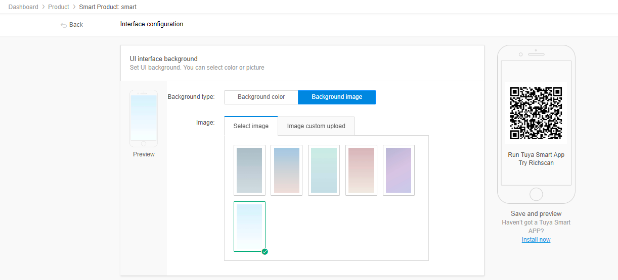
3. If you select a custom panel, click **Edit** to change panel elements, such as the background color and image.


### Debugging Hardware
#### Hardware Configuration
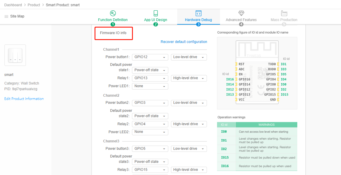
**I/O Port Configuration**
The firmware works based on whether the selected I/O ports are at high level or low level. For example, if you configure GPIO3 as a button effective at low level, the firmware triggers the button when it detects that the button input signal of GPIO3 has changed from high to low. If you incorrectly connect the GPIO3 button to an LED indicator or relay, the firmware cannot detect the input signal of the button.
**Feature Configuration**
The firmware can implement different functional features through personalized configuration. For example, if **Reset time/s** is set to **3**, press and hold the power button for more than 3s to change the network configuration mode.
**Other Hardware Configuration**
The firmware works according to the parameters that you specify. For example, select the bl0937 or hlw8012 chip as the power statistics chip and 1 mΩ or 2 mΩ as the current sampling resistance.
#### Precautions
1. After you save the settings and the module is delivered, the module's I/O port settings and functional features cannot be modified. If the actual I/O port settings of the module are different from those in the hardware diagram, modify and save the configuration of the module. A new module with the modified I/O port settings and functional features will be delivered. Before modifying the module's configuration, confirm the I/O port settings with the hardware engineer who designed the circuit diagram to ensure correct configuration.
2. Currently, the power statistics socket only supports pulse count power statistics chips, for example, bl0937 and hlw8012. If you select other types of chips, the power statistics function will become unavailable.
Table 4-1 I/O port description
| | IO0 | IO1 | IO2 | IO3 | IO4 | IO5 | IO12 | IO13 | IO14 | IO15 | IO16 |
| ------------- | ------------------------------------------- | ------------------------------------------- | ------------------------------------------- | -------------------------- | -------------------------- | -------------------------- | -------------------------- | -------------------------- | -------------------------- | --------------------------------------------- | ------------------------------------------- |
| E1S | Yes | Yes | Yes | Yes | Yes | Yes | Yes | Yes | Yes | Yes | No |
| E2S | No | Yes | No | Yes | Yes | Yes | Yes | Yes | Yes | No | No |
| E3S | Yes | Yes | Yes | Yes | Yes | Yes | Yes | Yes | Yes | Yes | Yes |
| If used | Connected to an external pulled up resistor | Connected to an external pulled up resistor | Connected to an external pulled up resistor | | | | | | | Connected to an internal pulled down resistor | Connected to an external pulled up resistor |
| Button | Low-level drive | Low-level drive | Not recommended | Low-level drive | Low-level drive | Low-level drive | Low-level drive | Low-level drive | Low-level drive | Unavailable | Low-level drive |
| LED indicator | Low-level drive | Not recommended | Not recommended | High-level/Low-level drive | High-level/Low-level drive | High-level/Low-level drive | High-level/Low-level drive | High-level/Low-level drive | High-level/Low-level drive | High-level drive | Low-level drive |
| Relay | Unavailable | Unavailable | Unavailable | High-level/Low-level drive | High-level/Low-level drive | High-level/Low-level drive | High-level/Low-level drive | High-level/Low-level drive | High-level/Low-level drive | High-level drive | Low-level drive |
#### Parameter Description
**Channel (Separate Control)**
* A channel is a module with the on-off control function. To enable or disable channels 1 and 2, press the corresponding buttons.
* When a channel is enabled, the relay is connected and the power indicator (if any) is on. When a channel is disabled, the relay is disconnected and the power indicator (if any) is off.
* When the module is powered off and then on, the relay and power indicator work based on the default power state.
**Power button**:
* The power button can be a physical or touch button.
* To enable or disable a channel, press the power button. To switch the network configuration mode, press and hold the power button.
* When there is a general button, the channel button can be null. If you do not select the general button, select at least one separate control button. A channel without a separate control button is enabled or disabled by the general button or App control panel.
**Default power state**:
* If you select **Power-off state**, the relay is disconnected each time the product is powered on.
* If you select **Power-on state**, the relay is connected each time the product is powered on.
* If you select **Power-off memory**, the relay status remains unchanged each time the product is powered on.
**Relay**:
* A relay has an on-off control function. During product design, the relay can be the control I/O interface of a socket, switch, or USB power supply port.
* The relay status can be controlled by the separate control button of the channel or the general control button.
* Each channel must have a relay.
**Power LED**:
* The power indicator indicates the relay status of a channel, rather than the power supply status of the product.
* After you select the I/O port of the power indicator, the firmware controls the relay indicator. When the relay is connected or disconnected, the power indicator is on or off, respectively.
* When you set the I/O port of the power indicator to **None**, use the hardware indicator to indicate the relay status. The I/O port of the relay is also used to control the on and off status of the LED indicator. If the hardware relay indicator is not used, use the Wi-Fi indicator as the relay indicator.
* Select a power indicator or **None** for each channel.
**Main Control Settings for a Socket with Two or More Ways**
**General power indicator**:
* When the general power indicator is not set to **None**, the indicator is on when one or more channels are enabled and off when all channels are disabled.
* You can select a general power indicator or set it to **None**.
**General button**:
* If the general button is not set to **None**, all channels are enabled or disabled when you press the general button. When you press and hold the general button, the network configuration mode changes.
* If there is a general button, all separate control buttons can be set to **None**. If the general button is set to **None**, select at least one separate control button.
**Switch button type**: An action is triggered after you press and release a push button switch, and an action is executed immediately after you tap a touch switch. Set the switch button type based on the panel type of your switch.
**Network Configuration Settings**
**Wi-Fi LED**:
* A Wi-Fi module has four working states: disconnected from the network, common network configuration, AP network configuration, and connected to the network.
* The Wi-Fi indicator has five display states: quick blinking, slow blinking, off, on, and indicating the relay status.
* When the Wi-Fi module is in common network configuration state, the Wi-Fi indicator blinks at 500 ms intervals. When the Wi-Fi module is in the compatible network configuration state, the Wi-Fi indicator blinks at 3s intervals. These Wi-Fi indicator status settings cannot be modified.
* Typically, the Wi-Fi indicator indicates the working status of the Wi-Fi module.
* Configure the Wi-Fi indicator status when the Wi-Fi module is disconnected from or connected to the network as follows:
**Wi-Fi indicator status when the Wi-Fi module is disconnected from the network:**
* **Light off**: The Wi-Fi indicator is off.
* **Light on**: The Wi-Fi indicator is on.
* **Indicate relay status**: The Wi-Fi indicator is on when at least one relay is connected and off when all relays are disconnected.
**Wi-Fi indicator status when the Wi-Fi module is connected to the network:**
* **Light off**: The Wi-Fi indicator is off.
* **Light on**: The Wi-Fi indicator is on.
* **Indicate relay status**: The Wi-Fi indicator is on when at least one relay is connected and off when all relays are disconnected.
| **Wi-Fi Module Status** | Disconnected from the network | Common network configuration | AP network configuration | Connected to the network |
| --------------------------------------- | ---------------------------------- | --------------------------------- | ------------------------ | ---------------------------------- |
| **Configurable Wi-Fi Indicator Status** | Yes | No | No | Yes |
| **Wi-Fi Indicator Status** | On/Off/Indicating the relay status | Common network configuration mode | Slow blinking | On/Off/Indicating the relay status |
There are two typical solutions. Solution 1 is the single-indicator solution, in which the Wi-Fi indicator indicates both the Wi-Fi network configuration status and the relay status. Solution 2 is the dual-indicator solution, in which the Wi-Fi indicator only indicates the Wi-Fi network configuration status. Another indicator shows the relay status. The following table describes the solution settings.
| | Wi-Fi module status | Disconnected from the network | Common network configuration | AP network configuration | Connected to the network |
| ----------------------------- | ---------------------- | ----------------------------- | ---------------------------- | ------------------------ | --------------------------- |
| **Single-indicator Solution** | Wi-Fi indicator status | Indicating the relay status | Quick blinking | Slow blinking | Indicating the relay status |
| **Dual-indicator Solution** | Wi-Fi indicator status | Off | Quick blinking | Slow blinking | On |
**1st time add device way**:
* **Blinking once powered on**: When you use the product for the first time, the Wi-Fi module automatically enters the common network configuration mode and the Wi-Fi indicator blinks quickly.
* **Long press to blinking**: When you use the product for the first time, the Wi-Fi module is disconnected from the network and enters the common network configuration mode after you press and hold the button.
**Reset time/s**: If you enter **3**, the network configuration mode of the Wi-Fi module is changed after you press and hold any button for over 3s. The value range is from 3 to 10, in seconds.
**Electricity Statistics Configuration**
**Chip selection**: Currently, only pulse count power statistics chips, such as bl0937 and hlw8012, are supported. If you select an incorrect chip, the power statistics function will become unavailable.
**Current sampling resistance(mΩ)**: The value can be **1**, **2**, or **5**, in milliohms. The value of **1** is recommended.
* Design the rated voltage ratio of the voltage sampling resistance based on 1 kΩ/3 x 680 kΩ, 1 kΩ/2 x 1 MΩ, or 1 kΩ/4 x 470 kΩ. If the sampling circuit is not designed based on the recommended resistance value, the power statistics value will be inaccurate and calibration will fail.
* After configuring and purchasing a trial-production module, do not change the sampling resistance. If the configured value is different from the actual value, the power statistics function will be inaccurate and calibration will fail.
**Over current protection(mA)**: If you require the overcurrent protection function, specify a current limit. If you do not need the overcurrent protection function, set this parameter to **0**. For example, if you require the relay to be disconnected automatically when the current is greater than 17.6 A, that is, 17600 mA, set this parameter to **17600**. Note that the current unit is milliampere (mA). It is recommended that **Over current protection** be set to a value about 10% higher than the relay specification.
**Rated voltage (V)**: The value can be **120** or **220**, in volts. You can only test and calibrate the power statistics function under the selected voltage. For details about the testing or calibration process, see the testing document. If the product can work properly under 120 V or 220 V, select either value as the testing or calibration voltage. If the designed voltage resistance of the product is less than 220 V, select 120 V as the testing or calibration voltage.
**Electricity statistics**: An I/O port of the module corresponds to the CF pin of the power statistics chip bl0937 or hlw8012. Typically, the IO4 port is used.
**C/V statistics**: An I/O port of the module corresponds to the CF1 pin of the power statistics chip. Typically, the IO5 port is used.
**C/V statistical switching**: An I/O port of the module corresponds to the SEL pin of the power statistics chip. Typically, the IO12 port is used. If both the I/O port of the module and SEL pin of the power statistics chip are connected to high level input, select **Positive connect**. If a reverse transistor or optical coupler is connected between the I/O port and SEL pin, which are respectively connected to high level input and low level input, select **Reverse connect**.
## Creating a Development-free 3-Way Socket on the Tuya Smart Platform
### Registering with and Logging In to the Tuya Smart Platform

1. Register with and log in to the Tuya Smart platform at .
2. (Recommended) Complete enterprise certification to upgrade your account to a corporate account with more functions.

### Creating a Development-free 3-Way Socket

1. On the **Product** page, click **Create** in the **Easy Access to Get Your Smart Product** area.
2. On the displayed **Create new product** page, choose **Electrical** and select a 3-way socket under **Plug and Play Solution**.
Alternatively, select a 3-way socket under **Custom** if the development-free solution cannot meet your product function requirements.
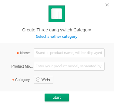
1. Specify the product name, which will be displayed on the App control panel.
2. Specify the internal or customer product model to facilitate product maintenance and order management.
3. After the product is created, click **Edit Product Information** on the product configuration page to modify the product name and model.
4. If you subscribe to a third-party service for the product, the third-party service subscription icon is highlighted for the product on the **Product** page.

### Configuring the App Control Panel
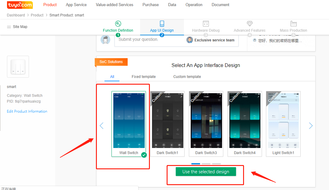
1. Click **App UI Design**. If you have upgraded your account to a corporate account, more templates and panel UI functions are available.
2. Select a control panel template and use the Tuya Smart or Smart Life App to scan the QR code to verify the control panel effect.
3. If you select a custom panel, click **Edit** to change panel elements, such as the background color and image.

### Debugging Hardware
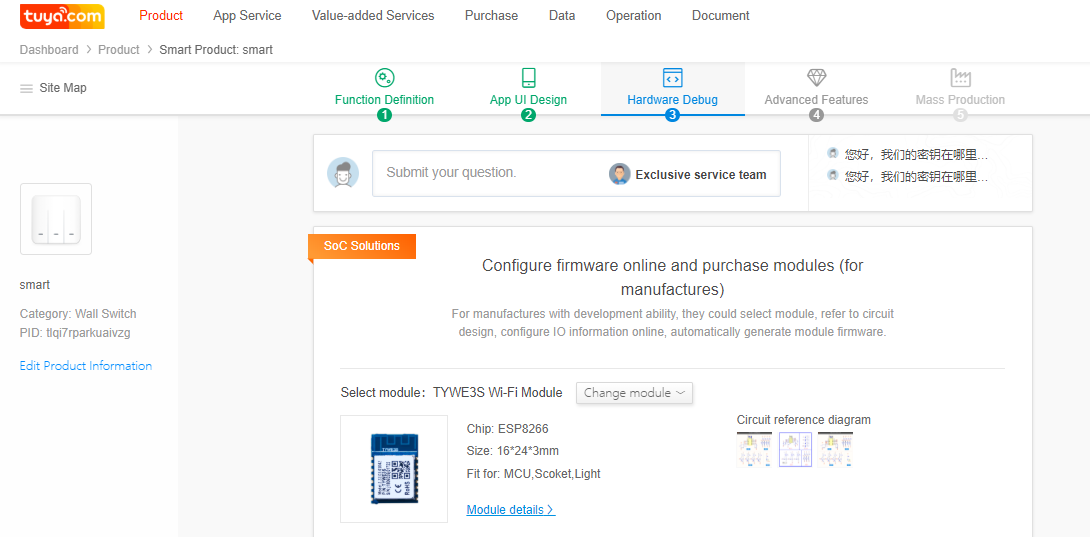
1. Select a module and check the circuit reference diagram. If you change the module, the circuit reference diagram is updated. You are advised to select a recommended module that supports most product functions and can meet your product requirements. Change a module if it is improper.
1. Configure I/O port information based on your actual requirements. Refer to *Creating a Development-free Electrical Engineering Product*
1. Click **Purchase** at the bottom of the **Hardware Debug** page to purchase the required module.
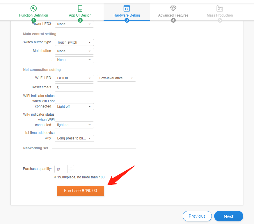
Note: The module will be programmed based on the settings that you specify on this page. After the module is delivered, the settings cannot be modified. If you modify the settings after the module is delivered, any online upgrades will not apply to the product because the settings will be inconsistent.
## Creating a Development-free Smart Power Statistics Socket on the Tuya Smart Platform
### I. Registering with and Logging In to the Tuya Smart Platform

1. Register with and log in to the Tuya Smart platform at [https://iot.tuya.com](https://iot.tuya.com/).
2. (Recommended) Complete enterprise certification to upgrade your account to a corporate account with more functions.

### II. Creating a Development-free Smart Power Statistics Socket

1, On the **Product** page, click **Create** in the **Easy Access to Get Your Smart Product** area.
2, (Recommended) On the displayed **Create new product** page, choose **Electrical** and select **Power statistics socket** under **Plug and Play Solution**. Alternatively, select a product under **Custom** if the development-free solution cannot meet your product function requirements.


3, Specify the product name, which will be displayed on the App control panel.
4, Specify the internal or customer product model to facilitate product maintenance and order management.
5, After the product is created, click **Edit Product Information** on the product configuration page to modify the product name and model.
6, If you subscribe to a third-party service for the product, the third-party service subscription icon is highlighted for the product on the **Product** page.


### III. Configuring the App Control Panel

1. Click **App UI Design**. If you have upgraded your account to a corporate account, more templates and panel UI functions are available.
2. Select a control panel template and use the Tuya Smart or Smart Life App to scan the QR code to verify the control panel effect.
3. If you select a custom panel, click **Edit** to change panel elements, such as the background color and image.


### IV. Debugging Hardware
The following describes how to configure the TYWE3S module.

1, Select a suitable module and check the reference circuit diagram. If you change the module, the reference circuit diagram will be updated.\
If you need a plug-in module, select the WR2 or TYWE2S module.\
If you need an SMT module, select the WR3 or TYWE3S module.

**2, Configure channels.**
(1) Select **High-level drive** or **Low-level drive** for **Power button 1**, **Relay 1**, and **Wi-Fi LED** based on actual requirements.
(2) Set **Default power state** based on actual requirements.
If you select **Power-off state**, the relay is disconnected each time the product is powered on. If you select **Power-on state**, the relay is connected each time the product is powered on.
If you select **Power-off memory**, the relay status remains unchanged each time the product is powered on.
(3) Set **Power LED** to **None** if you only need a single indicator or **GPIO3** if you need dual indicators.
**3, Set network configuration parameters.**
There are two typical solutions.\
Solution 1 is the single-indicator solution, in which the Wi-Fi indicator indicates both the Wi-Fi network configuration status and the relay status.\
Solution 2 is the dual-indicator solution, in which the Wi-Fi indicator only indicates the Wi-Fi network configuration status. Another indicator shows the relay status.


**4. Set electricity statistics parameters.**
(1) **Chip selection**: Currently, only pulse count power statistics chips, such as bl0937 and hlw8012, are supported. If you select an incorrect chip, the power statistics function will become unavailable.
(2) **Current sampling resistance(mΩ)**: The value can be **1**, **2**, or **5**, in milliohms. You are advised to select **1**.
(3) **Electricity statistics**: An I/O port of the module corresponds to the CF pin of the power statistics chip bl0937 or hlw8012. Typically, the IO4 port is used.
(4) **C/V statistics**: An I/O port of the module corresponds to the CF1 pin of the power statistics chip. Typically, the IO5 port is used.
(5) **C/V statistical switching**:\
An I/O port of the module corresponds to the SEL pin of the power statistics chip. Typically, the IO12 port is used.\
If both the I/O port of the module and SEL pin of the power statistics chip are connected to high level input, select **Positive connect**. If a reverse transistor or optical coupler is connected between the I/O port and SEL pin, which are respectively connected to high level input and low level input, select **Reverse connect**.
(6) **Rated voltage**:\
The value can be **120** or **220**, in volts. You can only calibrate the power statistics function under the selected voltage. If the product can work properly under 120 V or 220 V, select either value as the calibration voltage. If the designed voltage resistance of the product is less than 220 V, select 120 V as the calibration voltage.
(7) **Over current protection(mA)**:\
If you require the overcurrent protection function, specify a current limit. If you do not need the overcurrent protection function, set this parameter to **0**. For example, if you require the relay to be disconnected automatically when the current is greater than 17.6 A, that is, 17600 mA, set this parameter to **17600**. Note that the current unit is milliampere (mA). It is recommended that **Over current protection** be set to a value about 10% higher than the relay specification.
Note: After you save the settings and the module is delivered, the module’s I/O port settings and functional features cannot be modified. If the actual I/O port settings of the module are different from those in the hardware diagram, modify and save the configuration of the module. A new module with the modified I/O port settings and functional features will be delivered. Before modifying the module’s configuration, confirm the I/O port settings with the hardware engineer who designed the circuit diagram to ensure correct configuration.
For details on how to configure Advanced Features and Mass Production, see the SoC development process.